RV-Type and CAV-Type Flight Vehicles as Reference Vehicles
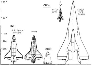
In the following chapters we refer to RV-type and CAV-type flight vehicles as reference vehicles. They represent the two principle vehicle classes on which we—regarding the basics of aerothermodynamics—focus our attention. ARV’s combine their partly contradicting configurational demands, whereas AOTV’s are at the fringe of our interest. Typical shapes of some RV’s and CAV’s are shown in Fig. 1.2.
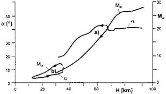
Characteristic flight Mach number and angle of attack ranges as function of the altitude of the Space Shuttle Orbiter, [15], and the SANGER TSTO space-transportation system, [16], up to stage separation are given in Fig. 1.3. (Basic trajectory considerations can be found in [5].) During the re-entry flight of the Space Shuttle Orbiter the angle of attack initially is approximately a = 40° and then remains larger than a = 20° down to H « 35 km, where the Mach number is Ыж « 5. SANGER on the other hand has an angle of attack below a = 10° before the stage separation at Ыж « 7 occurs.
The ranges of the flight altitude H, the flight Mach-number MTO, and the angle of attack a, together with a number of other vehicle features govern the
|
Fig. 1.2. Shape (planform) and size of hypersonic flight vehicles of class 1 (RV’s) and class 2 (CAV’s) [17]. HYTEX: experimental vehicle studied in the German Hypersonics Technology Programme [18]. |
|
Fig. 1.3. Flight Mach number Мж and angle of attack a of a) the Space Shuttle Orbiter, [15], and b) the two-stage-to-orbit space-transportation system SANGER up to stage separation, [16], as function of the flight altitude H. |
aerothermodynamic phenomena found at a hypersonic flight vehicle. We give an overview of these features together with some of the resulting typical flow features in Table 1.2 on page 9. The considered vehicles are the Space Shuttle (SS) Orbiter and the lower stage (LS) of SANGER, each at a characteristic trajectory point.
Regarding the flow features we look only at some of them found along the lower symmetry lines of the two vehicles. Apart from the nose region and the
beginning of the boattailing (x/L = 0.82), the lower (windward) symmetry line of the Space Shuttle (SS) Orbiter has no longitudinal curvature. (The lower side of the vehicle is mostly flat at 0.12 ^ x/L ^ 0.82, see, e. g., [5].) At the lower stage (LS) of SANGER we consider only the forebody up to the location of the beginning of the inlets of the propulsion system [5]. The lower side actually is a pre-compression ramp for the inlets. Apart from the nose region it is flat.
Vehicle surface properties We note first that the lower side of the SS Orbiter has, except for the nose region, a rough surface, given by the tiles and the gaps between them of the thermal protection system (TPS). The SANGER LS has a smooth surface. This is a necessity—regardless of the structure and materials concept of the vehicle—because the boundary layer must not be influenced negatively by the surface properties (permissible surface properties, Section 1.3).
Aerothermoelasticity Both the static and the dynamic aerothermoelastic – ity are important flight vehicle issues. For the SS Orbiter generally it can be stated that surface deformations are of such a small magnitude that the flow field past it is not affected. The situation is different at the SANGER LS forebody. There temperature differences exist between the lower and the upper side, Section 7.3. These differences may lead to a static deformation of the approximately 55 m long forebody with large consequences for the flow, in particular the inlet-onset flow, the thrust of the propulsion system and the aerodynamic forces and moments of the vehicle [5]. The same holds for the dynamic deformation of the forebody.
Atmospheric fluctuations are not of influence for the SS Orbiter on its high trajectory elements. There density uncertainties are a matter of concern, Section 2.1. Below 60 to 40 km altitude atmospheric fluctuations have an influence on the laminar-turbulent transition process. This holds for the Orbiter, but in particular for the SANGER LS, which flies at most at 33 km altitude. At the Orbiter the thermal loads are affected by the laminar – turbulent transition, whereas the drag increase does not matter.
Surface radiation cooling of external surfaces reduces the thermal loads to a degree that re-usable thermal protection systems (RV’s) and hot primary structures (CAV’s, partly found also at RV’s), become possible at all, Chapter 3. The external surfaces of both the considered vehicles are radiation cooled, the SS Orbiter, however, only at the surface portions which are exposed to the free stream (windward side). The in Table 1.2 given emissivity coefficients (necessary surface properties, Section 1.3) are nominal ones. The real ones are of that order of magnitude. At non-convex surface portions, the (fictitious) emissivity coefficient is smaller, Sub-Section 3.2.5.
High-temperature real-gas effects are present in both the inviscid and the viscous flow field past the windward side of the SS Orbiter. They are due to the high total enthalpy and the strong compression of the air stream at the vehicle surface. In Fig. 2.4 it is indicated—although the here considered trajectory point lies just outside of the graph—that
chemical non-equilibrium of the major constituents of air is present. Accordingly catalytic surface recombination is possible, Sub-Section 4.3.3, if the related permissible surface properties, Section 1.3, are exceeded. Then also heat transfer due to mass diffusion happens, in addition to the anyway present molecular heat transfer, Sub-Section 4.3.3.
At the SANGER LS high-temperature real-gas effects are small, Fig. 2.4. The total enthalpy of the free-stream in this case is much smaller than in the SS Orbiter case. Nevertheless, vibration excitation of O2 and N2 is present and—at most weak—dissociation of O2. Hence surface catalytic recombination is not a topic and also not heat transfer by mass diffusion.
Low-density effects The Knudsen numbers for the two flight vehicles at the given trajectory points are such that no low-density effects occur, Fig. 2.6. Possible exceptions are air data gauges and measurement orifices.
Entropy layer The SS Orbiter has a blunt nose region and the SANGER LS a blunt nose. At a blunt configuration at supersonic or hypersonic flight speed due to the curved bow-shock surface an entropy layer appears, SubSection 6.4.2. At a symmetric body at zero angle of attack it has a shape which resembles a slip-flow boundary-layer profile (see Fig. 9.26 on page 370), the symmetric case in Fig. 6.22. In the asymmetric case a wake-like entropy layer appears, at least around the lower symmetry plane [5]. In our cases this situation is given. Entropy-layer swallowing must be taken into account in boundary-layer computation schemes and it plays a role in laminar-turbulent transition.
Flow three-dimensionality Above we have noted the geometrical situation along the lower symmetry lines of the two vehicles. Hence boundary-layer flow three-dimensionality is present at the SS Orbiter in the nose region and in down-stream direction for x/L ^ 0.12. At the SANGER LS the flow on purpose is two-dimensional at the lower side of the forebody (inlet onset flow [5]), Fig. 7.8.
Laminar-turbulent transition does not happen at the SS Orbiter at the considered trajectory point. The unit Reynolds number is much too low there, upper left part of Fig. 2.3. However, at deflected trim or control surfaces transition-like phenomena might appear. At the Orbiter striation heating was observed at the body flap, possibly due to Gortler instability, Sub-Section 8.2.8. Further down on the trajectory, where the unit Reynolds number becomes large, of course laminar-turbulent transition happens. At 45 km altitude it happens at the lower side already at about 30 per cent vehicle length, Fig. 3.3. At the other surface portions it will happen further down on the trajectory. Due to the TPS tile surface at the SS Orbiter lower side, transition there is roughness-dominated, Sub-Section 8.3.1.
At the SANGER LS laminar-turbulent transition in any case happens, due to the low flight altitude. The prediction of the shape and the location of the transition zone today still is not possible to the needed degree of accuracy. At the upper side of the forebody transition will occur further downstream than at the lower side. One of the reasons is that at the upper side the unit
|
Table 1.2. Characteristic features of the flow at the lower side of the Space Shuttle Orbiter and of the SANGER lower stage’s forebody, each at a distinctive trajectory point.
|
Reynolds number is approximately only one third of that at the lower side. The lower side is a pre-compression surface for the inlets, whereas the upper side is more or less a free-stream surface.[7] The SANGER LS is an aircraft-like flight vehicle and definitely transition sensitive, Chapter 8.
Boundary-layer edge Mach number The windward side boundary layer at the SS Orbiter at large angle of attack initially is a subsonic, then a transonic, and finally a low supersonic, however, not ordinary boundary layer. During re-entry one has typically at maximum Me « 2.3, and mostly Me ^ 2 [19]. This is in contrast to the boundary layer at the lower side of the SANGER LS. There a true hypersonic boundary layer exists with appreciably high edge Mach numbers.
Boundary-layer edge temperature The boundary-layer edge flow at the SS Orbiter is characterized by very large temperatures and hence high- temperature real-gas effects. The given boundary-layer edge temperature at the stagnation point is guessed to be approximately 9,000 K from Fig. 2.3. Assuming for the expansion to Me = 2,3 an effective ratio of the specific heats Yeff = 1.14, [20], we arrive at T « 6,500 K at the beginning of the boattailing.
At the SANGER LS due to the flight at small angle at attack, no large compression effects occur. We find them only in the blunt nose region and possibly at (swept) leading edges, inlet ramps and trim and control surfaces [5]. Hence the boundary-layer edge temperatures are moderate to low and the rather mild high-temperature real-gas effects are essentially restricted to these configuration parts and to the boundary layers.
Wall temperature The radiation cooling of the vehicle surfaces is very effective. This holds in particular for the SS Orbiter due to the small unit Reynolds number at the large altitude, the large surface curvature radii at the stagnation-point region and the then more or less flat surface. The radiation cooling at the SANGER LS would reduce the surface temperature even down to approximately 500 K, if the boundary layer would remain laminar, Section 7.3. Actually laminar-turbulent transition occurs with a subsequent rise of the wall temperature level to about 1,000 K. At the vehicle’s nose the contradictory demands of minimization of wave drag and wall temperature exist. The first demand asks for small nose radii and the latter for large ones. The reader is referred in this regard to, e. g., [5, 21]. We note also that the radiation-adiabatic temperature Tra in general is a good approximation of the actual wall temperature Tw, Chapter 3.
Boundary-layer temperature and density gradients Due the rather low surface temperatures because of the radiation cooling, strong wall-normal temperature gradients are found at the SS Orbiter. At the SANGER LS medium gradients are present for laminar flow and large ones for turbulent flow. Note that the resulting heat fluxes in the gas at the wall qgw are not the heat fluxes qw which enter the surface of the TPS or the hot primary
structure. In general we have qw ^ qgw because of the large amount of heat qrad radiated away from the surface, Chapter 3. Because at both flight vehicles the attached viscous flow to a good approximation is a first-order boundary – layer flow, the density gradients are inverse to the temperature gradients [22].
Thermal surface effects—viscous At the SS Orbiter viscous thermal surface effects, Section 1.4, are negligible except to a certain degree at the deflected trim and control surfaces as well as at the thrusters of the reaction control system [5]. This is in stark contrast to the SANGER LS, where viscous thermal surface effects are of utmost importance. In this regard a number of examples is given in several chapters and in particular in Chapter 10.
Thermal surface effects—thermo-chemical These effects concern mainly surface catalytic recombination at the SS Orbiter due to the very hot boundary layer and the resulting thermo-chemical non-equilibrium of the flow, see also Chapter 10.


 It is not intended to introduce such a new paradigm in this book. However, it is tried to present and discuss aerothermodynamics in view of the major roles of it in hypersonic vehicle design, which reflects the need for such a new paradigm.