We consider exclusively the relevant classical thicknesses of laminar and turbulent flow boundary layers. Their dependencies on the boundary-layer running length x, on the Reynolds number Reref, x, and on the reference temperature T* are studied. Thermal and mass-concentration boundary layers can be treated likewise.
Boundary-Layer Thicknesses. The flow boundary-layer was introduced in Sub-Section 4.3.1. We call it—as usual—in the following simply “boundary layer”. It causes a virtual thickening of a body (via its displacement properties), and it in particular prevents a full re-compression of the external inviscid flow at the aft part of the body, where we have a flow-off separation of the boundary layer, and the formation of a wake [1]. This is the cause of the viscosity-induced pressure or form drag of a body.[95] The boundary layer also reduces the aerodynamic effectiveness of lifting, stabilizing, and control surfaces. Its thickness finally governs the height of the boundary-layer diverter in the case of airbreathing propulsion, Sub-Section 6.1. In all cases it holds: the thicker the boundary layer, the larger is the adverse effect.
On the other hand we have the effect that the boundary-layer causes and governs the wall-shear stress and the thermal state of the surface. The thicker the boundary layer (with turbulent flow the viscous sub-layer), the smaller the wall-shear stress, the smaller the heat-flux in the gas at the wall, and, in particular, the more effective is surface-radiation cooling.
Attached viscous flows, i. e., boundary layers, have finite thickness everywhere on the body surface, also in stagnation points, and at swept leading edges, i. e., attachment lines in general, see, e. g., [1, 21, 22].
Of special interest is the thickness of a boundary layer as such, its displacement thickness, and the thickness of the viscous sub-layer, if the flow is turbulent.
The thickness 6 of a laminar boundary layer is not sharply defined. Boundary-layer theory yields the result that the outer edge of the boundary layer lies at y [21].
For the incompressible laminar flat-plate boundary layer the theory of Blasius gives for the thickness
with[96]
Poo Woo ж Q„s
‘ .., =—————- • (7.89)
In terms of the unit Reynolds number ReU — p^u^/y.^ it reads:
x0.5
Slam = C n 5 , (7.90)
(Re^o)0.5
A practical definition of 6 for laminar boundary layers is the distance at which locally the tangential velocity component u(y) has approached the inviscid external velocity ue by є ue (for three-dimensional boundary layers the resultant tangential velocity and the resultant external inviscid velocity are taken)[97]
Ue – u(y) A єие. (7.91)
Usually, although often not explicitly quoted, the boundary-layer thickness is defined with
є — 0.01. (7.92)
For the incompressible flat-plate boundary layer we find with this value from the Blasius solution the constant c in eq. (7.88):
є — 0.01: c — 5. (7.93)
If є — 0.001 is taken, the constant is c — 6. The exact Blasius data are c — 5: u — 0.99155 ue, c — 6: и — 0.99898 ue.
The outer edge of a turbulent boundary layer in reality has a rugged unsteady pattern. In the frame of Reynolds-averaged turbulent boundary – layer theory it is defined as smooth time-averaged edge. The concept of the
thermal and the mass-concentration boundary layer, as we use it for laminar flow, is questionable with regard to turbulent flow.
For a low-Reynolds number, incompressible turbulent flat-plate boundary layer the boundary-layer thickness is found, by using the ^-th-power velocity distribution law [24], to[98]
x
Sturb = (7-94)
and in terms of the unit Reynolds number
x0.8
Sturb = 0:i7jm^- (7-95)
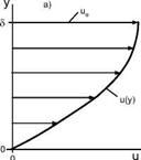
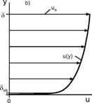
A very important thickness of turbulent boundary layers is that of the viscous sub-layer Svs, which is small compared to the boundary-layer thickness 5turb (Svs/ Slurb = O(0.01)), Fig. 7.5 b).
Fig. 7.5. Two-dimensional tangential velocity profile and boundary-layer thickness of a) laminar, b) turbulent boundary layer (time averaged).
In laminar boundary layers the thickness S is the characteristic thickness which governs shear stress and heat transfer at the wall. In turbulent flow the characteristic thickness is Svs, Fig. 7.6.
This thickness is found from the general definition of the viscous sub-layer:
y+ = < 5. (7.96)
A* ~
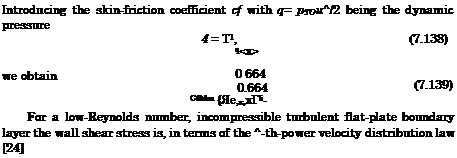
With the friction velocity uT = Jтш/p and the wall-shear stress of the ^-th-power boundary layer, eq. (7.140) in Sub-Section 7.2.3, we obtain (see also [25], where the different co-factor 72.91 results)
x
Svs = 29-ll(i n, , ■ (7-97)
G. Simeonides proposes for scaling purposes, in order to be consistent with the laminar approach, an alternative thickness, Ssc, which is slightly different from the viscous sub-layer thickness Svs [26]. With the definition of Ssc lying where the non-dimensional velocity u+ and the wall distance y+ are equal (u+ = u/uT = y+ = ypuT/у) he gets the scaling thickness 5sc for turbulent boundary layers
x
^=33-7v:,)o. s – (7-99)
We apply now the reference temperature concept in order to determine the dependence of the boundary-layer thicknesses on the wall temperature Tw and the Mach number, assuming perfect-gas flow.
We begin with a demonstration of the basic approach applied to the boundary-layer thickness of laminar flow Siam, c. We write eq. (7.88) in terms of the reference density and viscosity:
|
x
(2——————–
(p*u^x/p*)0-5
|
With
and the relations given in Sub-Section 7.1.6:
P^_Xо Moo _ fToo Ш
Poo _ T* ’ /V " V /
we find, with c = 5, the thickness 3lam, c of the compressible laminar flat-plate boundary layer[99]
If we assume T* ж Tw, as well as w ж 1, we obtain that the compressible boundary-layer thickness depends approximately directly on the wall temperature:

 (7.101)
At an adiabatic wall the recovery temperature is:
 Tr = Tw=T^(l + r^-±Mi2-
This relation says that for large Mach numbers Tr ж M2. Introducing this into eq. (7.101) we get the well known result for the compressible laminar adiabatic flat-plate boundary layer:
For the thickness of the compressible turbulent flat-plate ^-th-power boundary layer we obtain with the reference-temperature extension
and for the thickness of the viscous sub-layer eq. (7.97)
whereas the turbulent scaling thickness, eq. (7.99), is
Integral Parameters 5i and S2- Well defined integral parameters are the boundary-layer displacement thickness S1, the momentum thickness S2 and others.[100] These parameters appear on the one hand in boundary-layer solution methods (“integral” methods of Karman-Pohlhausen type [21]), and on the other hand in empirical criteria for laminar-turbulent transition, for separation, etc. Often also quotients of them are used, for instance the shape factor H12 = S1/S2.
In the following we define the more important integral parameters. We do it in all cases for compressible flow. The definitions are valid for both laminar and turbulent flow and contain the definitions for incompressible flow. Because of the importance of the displacement of the external inviscid flow by the boundary layer (weak interaction) we quote S1 and the equivalent inviscid source distribution for three-dimensional flow.
In the frame of first-order boundary-layer theory and in Cartesian coordinates the displacement thickness S1 of a three-dimensional boundary layer is defined by a linear partial differential equation of first order, see, e. g., [1]
In this definition surface suction or blowing in the frame of the boundary – layer assumptions is taken into account by p0v0, which in general can be a function of x and z. The symbols S1x and S1z denote “components” of S1 in x and z-direction, which are determined locally
with pu and pw being functions of y.
The displacement thickness S1 of three-dimensional boundary layers can become negative, although the two local components S1x and S1z are everywhere positive [1].[101] The effect occurs especially at attachment lines, with a
steep negative bulging of the Si surface. Close to the beginning of separation lines a steep positive bulging is observed.[102] These effects are clues for the explanation of the hot-spot and the cold-spot situations along attachment and separation lines on radiation-cooled surfaces, Sub-Section 3.2.4.
For two-dimensional boundary layers eq. (7.107) reduces to
d
— peue{5 – d’ij] = p0v0 (x), (7.110)
which is the general definition of the boundary-layer displacement thickness in two dimensions. Only for p0v0 = 0, and peuex=0 = 0, we obtain the classical local formulation
In practice this two-dimensional formulation is almost always employed to determine the displacement properties of a boundary layer, usually without consideration of possible effects of three-dimensionality or, in two dimensions, of initial values, and of variations of the external flow. These can be relevant, for instance, at a wing with a round swept leading edge. Here a boundary layer with finite thickness exists already along the leading edge in span-wise direction. If the displacement thickness in chord-wise direction is to be determined, eq. (7.110) must be solved while properly taking into account the displacement thickness of the leading-edge boundary layer as initial value.
If boundary-layer criteria are correlated with the displacement thickness, the use of the proper definition is recommended, otherwise the correlation may have deficits. However, criteria correlated with a given displacement thickness should be applied with the same definition, even if the displacement thickness employed in the correlation is not fully representative.
The displacement properties of a boundary layer lead to a virtual thickening of the body. In hypersonic computations by means of coupled Euler/boun – dary-layer methods this thickening must be taken into account. To change the body contour by a local superposition of the positive or negative displacement thickness would be a cumbersome procedure. A very effective alternative is to employ the equivalent inviscid source distribution pvisd [27]
This source distribution, which is a function of x and z, is found in a coupled solution method after the first Euler and boundary-layer solution has been performed. It is then employed at the body surface as boundary condition for the next Euler solution. In this way the boundary-layer displacement
properties are iteratively taken into account. In practice only one coupling step (perturbation coupling) is sufficient [1, 28].
An integral parameter often used in correlations is the momentum thickness 62.[103] In three-dimensional boundary layer flow two such thicknesses appear (62x and 62z), because the momentum flux is a vector [1]. In practice only the classical two-dimensional formulation
is employed either for the main-flow profile or assuming two-dimensional flow from the beginning.
So far we have discussed the definitions of integral parameters. We give now displacement and momentum thicknesses for two-dimensional laminar and turbulent boundary layers over flat surfaces, which we also extend by means of the reference temperature to compressible flow. We do this again in order to identify their dependencies on wall temperature and Mach number, and to permit estimations of these thicknesses for practical purposes.
For the laminar Blasius boundary layer we quote [21]
and for the turbulent ^-th-power boundary layer [24]
x
h, turb, ic = 0-0360 ‘ (7.117)
(Re^,x)
The respective shape factors are
H12,lam, ic = dl’lam’ic = 2.591, (7.118)
62,lam, ic
for the Blasius boundary layer, and
H12,turb, ic = dl’turb’ic = 1.286, (7.119)
62,turb, ic
for the ^-th-power boundary layer.
Because the tangential velocity profile of a turbulent boundary layer is much fuller than that of a laminar one, Fig. 7.5, its displacement thickness, but also its momentum thickness, are smaller in proportion to the boundary – layer thickness than those of a laminar boundary layer, Table 7.2.
|
Table 7.2. Ratios of displacement thickness S1 and momentum thickness S2 to boundary-layer thickness S for the laminar (Blasius, e = 0.01) and the turbulent
(=-th-power) boundary layer.
|
Thickness ratio
|
Laminar boundary layer
|
Turbulent boundary layer
|
|
Si/6
|
0.3442
|
0.1328
|
|
52/5
|
0.1251
|
0.0973
|
|
This points to a very important property of two-dimensional and threedimensional (main-flow profile) turbulent boundary layers, which in general holds also for hypersonic flow: close to the wall the flow momentum is proportionally larger than that of laminar boundary layers. A turbulent boundary layer hence can negotiate a stronger adverse pressure gradient than a laminar one, and therefore separates later than a laminar one. Although the skin friction exerted by a turbulent boundary layer is larger, a body of finite volume may have a smaller total drag if the flow is turbulent, because with the same pressure field the laminar flow will separate earlier. The classical examples are the drag behavior as function of Reynolds number of the flat plate at zero angle of attack and of the sphere [21]. However, regarding the thermal state of a radiation, or otherwise cooled vehicle surface, the turbulent boundary layer has no such positive secondary effect.
We do not show the derivation of the reference-temperature extensions of the above displacement and the momentum thicknesses to compressible flow, because the effort would be too large. Instead we quote them from [16, 29], taking Pr = 0.72, and rfam = /Pr = 0.848, r*turb = fPr = 0.896.
Summary. We discuss the relations for the boundary-layer thicknesses and the integral parameters together. First, however, we consider the different factors, which we quoted for the displacement thickness of incompressible 4-th-power turbulent boundary layers, eqs. (7.116) and (7.123), and the different values of the shape factor in eqs. (7.119) and (7.127).
Discrepancies can be found in the literature regarding all simple relations for two-dimensional incompressible and compressible flat-plate turbulent boundary layers. Possible reasons in such cases are that not enough information is given:
— The relations in general are valid only in a certain Reynolds-number range. The thicknesses for the th-power turbulent boundary layer, which we gave above, Sturb, ic, eq. (7.94), Svs, eq. (7.97), as well as the integral parameters Si, turb, ic, eq. (7.116), and S2,turb, ic, eq. (7.117), are valid only for moderate Reynolds-numbers of « O(105) to « O(107) [24]. For larger Reynolds numbers other factors in these relations or completely other relations are required, which can be found in the literature.
— The above relations assume that the boundary layer is turbulent from the leading edge of the flat plate onwards. Relations or factors derived from measurement data may not take this into account and hence differ from these relations. The classical shape-parameter data of Schubauer and Klebanoff [30] vary in the transition region of a flat plate in incompressible flow from H12 = 2.6 in the laminar part to H12 = 1.4 in the turbulent part. They are of course locally determined data. The value for the laminar part compares well with the value given in eq. (7.118), whereas the value for the turbulent part is larger than that given in eq. (7.119). Obviously it was employed in eq. (7.123).
We mention that the location of laminar-turbulent transition, if desired, can easily be taken into account in the determination of the boundary-layer thicknesses with a simple approach. In [31] a procedure is given which works with the virtual origin of the turbulent boundary layer.
The virtual origin is found from the matching of the momentum deficits of the two boundary layers on both sides of the transition location xtr: xi, j = X2,j, Fig. 7.7:
(peu2e52)2 = (PeU2e52)\, (7.128)
with S2 being the momentum-loss thickness.
|
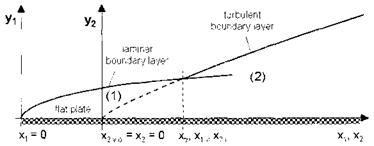
Fig. 7.7. Illustration of the virtual origin of a boundary layer at a junction demonstrated by means of flat-plate laminar-turbulent transition [1].
|
This matching can also be used at flat plate/ramp junctions etc. [16]. A detailed description of the procedure can be found in [1].
— The wall temperature (thermal state of the surface) and the Mach number influence as well as the surface properties may have not been taken properly into account.
It is not attempted here to rate the available relations or to recommend one or the other. Basically it is intended to show the dependencies of thicknesses and integral parameters on typical flow and other parameters, which the engineer or researcher should know. Besides that the relations should permit to obtain an estimation of the magnitude of these entities with reasonable accuracy.
We combine now the above results in Table 7.3. We substitute ‘TO’ conditions by general ‘ref’ conditions and chose ш = ш^ = 0.65 in the viscosity law, Section 4.2.[104] We break up all Reynolds numbers Re into the unit Reynolds number Reu and the running length x in order to show the explicit dependencies on these parameters.
An inspection of the reference-temperature relation eq. (7.70) and the reference-temperature extensions eqs. (7.100), (7.104), (7.105) and (7.106), (7.120) to (7.124) shows, that we can write all temperature-extension terms symbolically as)
This form shows the desired limit behavior, since for incompressible flow with Mref = 0 the last term in the large brackets vanishes, and with Tw = Tref the two first terms in sum have the value ‘1′.
The reference-temperature extension relations of the integral parameters 51,iam, c, eq. (7.120), and S1iturb, c, eq. (7.122), have different factors in the large brackets, but these factors are quite close to those in the original reference temperature relation, eq. (7.70). Therefore we use eq. (7.129) in order to contract these relations for an easier discussion. In Table 7.3 they are marked accordingly with ‘m’.
The third and the fourth column in Table 7.3 give the basic dependencies of the thicknesses of both incompressible and compressible boundary layers on the running length x and the unit Reynolds number ReUef, the fifth column the dependence of the thicknesses of compressible boundary layers on the reference-temperature ratio T*/Tref, i. e., implicitly on the wall temperature Tw and the Mach number Mref, eq. (7.129).
The dependencies summarized in Table 7.3 give us insight into the basic behavior of thicknesses and integral parameters of two-dimensional flat-plate boundary layers. The results also hold for not too strongly three-dimensional flow over flat surfaces.
— Dependence on the boundary-layer running length x.
All boundary-layer thicknesses increase with increasing x. The thicknesses of turbulent boundary-layers grow stronger (ж x0 8) with x than those of laminar boundary layers (ж x0 5). The thickness of the viscous sub-layer grows only very weakly with x, ж x01, and also the turbulent scaling thickness, ж x0 2.
|
Table 7.3. Dependence of boundary-layer thicknesses on the running length x, the unit Reynolds number ReUef, and the reference-temperature ratio T*/Tref (ш = = 0.65). Manipulated relations (see above) are marked with ‘m’.
|
Thickness
|
eq.
|
X
|
Re^f
|
Т /Tr&f
|
|
&larri
|
(7.100)
|
OC :r°’6
|
ж (Reuref)-°-b
|
«tef“
|
|
&turb
|
(7.104)
|
OC :r0’8
|
ж {Reurefy0-2
|
«(*Г
|
|
3l, lam
|
(7.120)
|
OC :r°’6
|
ж (Де:“е/)-°-Б
|
/ 0.825
<х fcL
|
|
$1 ,turb
|
(7.122)
|
OC :r°’8
|
ж (Де:“е/)-°-2
|
* (*)Г
|
|
^2,lam
|
(7.121)
|
OC :r°’6
|
ж (Де:“е/)-°-Б
|
«(*Г’“
|
|
$2 ,turb
|
(7.124)
|
OC :r°’8
|
ж (Де:“е/)-°-2
|
«(*Г7
|
|
$vs
|
(7.105)
|
ОС Х0Л
|
ж (Де:“е/)-°-9
|
«(*Г“
|
|
Ssc
|
(7.106)
|
OC :r°’2
|
ж (де:“е/г°-8
|
«(*Г
|
|
— Dependence on the unit Reynolds number ReUef.
All thicknesses of boundary-layers depend on the inverse of some power of the unit Reynolds number. The larger ReUef, the smaller are the boundary – layer thicknesses. Thicknesses of laminar boundary layers react stronger on changes of the unit Reynolds number (ж (ReUef )-0’5) than those of turbulent boundary layers (ж (ReUef )-0 2). Strongest reacts the thickness of the viscous sub-layer, ж (ReUef )-0 9, and that of the turbulent scaling thickness, ж (Re%ef )-0’8.
— Dependence on T*/Tref.
relations are available to prescribe them. We note only the dependencies of
the boundary-layer thickness S, which holds for laminar and turbulent flow.
— Pressure gradient dp/dx in main-stream direction.
In general a negative pressure gradient (accelerated flow) reduces S, a positive (decelerated flow) increases it. The cross-flow pressure gradient dp/dz governs boundary-layer profile skewing and the form of the crossflow boundary-layer profile (see Sub-Sections 7.1.2 and 7.1.3).
— Change of the body cross-section dA/dx in main-stream direction.
If the cross-section grows in the main-stream direction (dA/dx > 0), see, e. g., Fig. 6.22 a), the boundary layer gets “stretched” in circumferential direction, because the wetted surface grows in the main-stream direction. With the same pressure field and the same boundary conditions S becomes smaller at such a body than over a flat plate [1]. This effect is the Man – gler effect [32]. Both wall-shear stress and heat flux in the gas at the wall are correspondingly larger. The inverse Mangler effect enlarges S. It occurs where the body cross-section in the main-stream direction is reduced (dA/dx < 0). A typical example is the boat-tailed after-body of a flight vehicle (Fig. 6.22 a), if the flow would come from the right-hand side).
— 3-D effects.
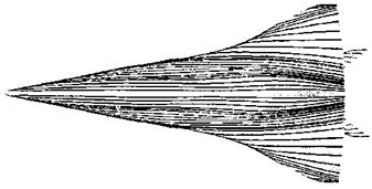
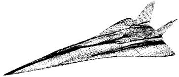
We mention here only the most obvious 3-D effects, which we find at attachment and separation lines [1]. We have discussed them in the context of surface-radiation cooling already in Sub-Section 3.2.4. At an attachment line, due to the diverging flow pattern, the boundary layer is effectively thinned, compared to that in the vicinity, Fig. 3.5. At a separation line, the flow has a converging pattern and hence the tendency is the other way around, Fig. 3.6. Consequently the boundary-layer thickness S is reduced at attachment lines, and enlarged at separation lines.
— Surface parameter k.







![Boundary-Layer Thicknesses and Integral Parameters Подпись: Fig. 7.6. Schematic of the characteristic thickness Schar in a boundary layer [1]. The location of the virtual origin of the turbulent boundary layer, see below, is denoted with xturb,v.o., the transition location with xtr.](/img/3130/image537_3.gif)


