Category Dynamics of. Atmospheric Flight

Longitudinal aerodynamic characteristics—part 2

CHAPTER 7

7.1 BOB WEIGHTS AND SPRINGS

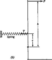
The control-force characteristics of manual-control systems can be modified by the introduction of weights and springs, as illustrated sche­matically in Fig. 7.1. When a spring, or bungee, is used as in Fig. 7.16, it is

Longitudinal aerodynamic characteristics—part 2Control column-

Подпись: Weights
nW

(a)

Fig. 7.1 Bob weight and spring, (a) Bob weight. (6) Spring.

usually so designed that it exerts a nearly constant force on the control column. Thus both weight and spring require an additive stick force ДP to maintain equilibrium. These forces are

Подпись: for the weightДР = nW – Ъ

Подпись: for the springДР — T­b

where n = 1 for rectilinear flight, and is given by (6.10,4) for a pull-up.

MANEUVERABILITY—ELEVATOR ANGLE AND CONTROL FORCE PER g

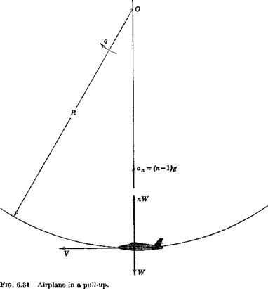
In this section we investigate the elevator angle and control force required to hold a vehicle in a steady pull-up with load factorf n (Fig. 6.31). The concepts discussed here were introduced by S. B. Gates, ref. 6.12. The flight – path tangent is horizontal at the point under analysis, and hence the net normal force is L— W = (n— l)W vertically upward. The normal acceleration is therefore (n — l)g.

When the vehicle is in straight horizontal flight at the same speed and altitude, the elevator angle and control force to trim are Se and P, respectively. When in the pull-up, these are changed to de + ASe and P + ДP. The ratios Adj{n — 1) and AP/(n — 1) are known, respectively, as the elevator angle per g, and the control force per g. These two quantities provide a measure of the maneuverability of the vehicle; the smaller they are, the more maneuverable it is.

The angular velocity of the airplane is fixed by the speed and normal acceleration (Fig. 6.31).

q = ІП – i)g (6.10,1)

As a consequence of this angular velocity, the field of the relative air flow past the airplane is curved. It is as though the machine were attached to the end of a whirling arm pivoted at 0. This curvature of the flow field alters the pressure distribution and the aerodynamic forces from their values in trans­lational flight. The change is large enough that it must be taken into account in the equations describing the motion.

j The load factor is the ratio of lift to weight, n — LjW. It is unity in straight horizontal flight.

MANEUVERABILITY—ELEVATOR ANGLE AND CONTROL FORCE PER g

We assume that q and the increments Да, ASe etc. between the rectilinear and curved flight conditions are small, so that the increments in lift and moment may he written

ACL = CLx Да + CfJ + CLi A6e (6.10,2)

= СШа Да + Стя4 + Gms A6e (6.10,3)

where q = qc/2V, CL^ — dGLjdq, Cm^ = dCm/d4 (see Sec. 5.13). The q derivatives are discussed in Sec. 7.9. In this form, these equations apply to any configuration. From (6.10,1) we get

which is more conveniently expressed in terms of Gw and ц (see Table 5.1),

4 = (n – 1) (6.10,4)

2fl

Since the curved flight condition is also assumed to be steady, i. e. without angular acceleration, then ДGm = 0. Finally, we can relate AGL to n thus:

= nrr = (» – 1 )0W (6.10,5)

Equations (6.10,2 and 3) therefore become

(n – 1)Cw = CLx Да + (n – 1)CLa °-S. + Gu Ade

‘ 0 = Gmx Да + (» – 1 )Cm^ + Cm3 Ade

Подпись: and Подпись: n — 1 Да Подпись: G MANEUVERABILITY—ELEVATOR ANGLE AND CONTROL FORCE PER g Подпись: (a) (6.10,6) (b)

which are readily solved for Да and Д6e to yield the elevator angle per g

Подпись: Да„ П — 1 MANEUVERABILITY—ELEVATOR ANGLE AND CONTROL FORCE PER g Подпись: (6'10Я

where Д is given by (6.4,13). As has been shown in Sec. 6.4 Д does not depend on C. G. position, hence the variation of Дdj(n — 1) with h is provided by the terms in the numerator. Writing (7 = 0LJh — hn) (6.10,6a) becomes

Подпись: A,, — Подпись: GMQ(K) 2J“ — GL(hrn) Подпись: (6.10,8)

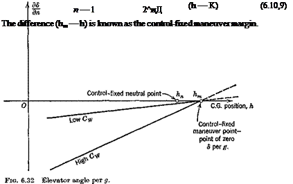
The derivatives CL and Gm both in general vary with h, the former linearly, the latter quadratically, (see Sec. 7.9). Thus (6.10,7), although it appears to be linear in h, is not exactly so. For airplanes with tails, 0L can usually be neglected altogether when compared with 2(i, and the variation of Gm^ with h is slight. The equation is then very nearly linear with h, as illustrated in Fig. 6.32. For tailless airplanes, the variation may show more curvature. The point where AdJ(n — 1) is zero is called the control-fixed maneuver point, and is denoted by hm, as shown. From (6.10,7) we see that

MANEUVERABILITY—ELEVATOR ANGLE AND CONTROL FORCE PER g

where Gm (hm) and CL (hm) are the values of these two derivatives evaluated for h hm. When Gm and CL^ can be assumed to be independent of h, (6.10,7) reduces to

CONTROL FORCE PER g

From (6.8,4) we get the incremental control force

AP = QSMpr* AGhe (6.10,10)

Ghe is given for rectilinear flight by (6.5,2). Since it too will in general be influenced by q, we write for the incremental value (Ad( = 0)

AGhe = СЫх Да + GKq + Ьг Аде (6.10,11)

MANEUVERABILITY—ELEVATOR ANGLE AND CONTROL FORCE PER g Подпись: -A’ ««. } (6.10,12)

The derivative Ch is discussed in Sec. 7.9. Using (6.10,4) and (6.10,66), (6.10,11) is readily expanded to give

From (6.6,4) we note that the last parenthetical factor is b2G’LJGL^ or Ъга’ ja. For Ade we use the approximation (6.10,9) in the interest of simplicity and the result for AGhe after some algebraic reduction is

= ~ Sr ~ h’m) (6.10,13)

n — 1 2(1 A

where h’m = K + 4г(тг + ) (6-10,14)

a b2CLx 2ц – CLJ

In keeping with earlier nomenclature, h’m is the control-free maneuver point and (h’m — h) is the corresponding margin. On noting that GwpVz is the wing loading w, we find the control force per g is given by

Q = ——г = ^ (2(t – CL )(h – h’n) (6.10,15)

n — 1 2(iA я

Note that this result applies to both tailed and tailless aircraft provided that the appropriate derivatives are used. The following conclusions may be drawn from (6.10,15).

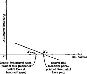
1. The control force per g increases linearly from zero as the C. G. is moved forward from the control-free maneuver point, and reverses sign for h > h’m.

MANEUVERABILITY—ELEVATOR ANGLE AND CONTROL FORCE PER g

2. It is directly proportional to the wing loading. High wing loading produces “heavier” controls.

3. For similar aircraft of different size but equal wing loading, Q oc Sece;

i. e. to the cube of the linear size.

4. Neither 0L nor V enters the expression for Q explicitly. Thus, apart from M and Reynolds number effects, Q is independent of speed.

5. The factor fi which appears in (6.10,14) causes the separation of the control-free neutral and maneuver points to vary with altitude, size, and wing loading, in the same manner as the interval (hm — hn).

Figure 6.33 shows a typical variation of Q with C. G. position. The state­ment made above that the control force per g is “reversed” when h > h’m must be interpreted correctly. In the first place this does not necessarily mean a reversal of control movement per g, for this is governed by the elevator angle per g. If h’m < h < hm, then there would be reversal of Q without reversal of control movement. In the second place, the analysis given applies only to the steady state at load factor n, and throws no light whatsoever on the transition between unaccelerated flight and the pull-up condition. No matter what the value of h, the initial control force and movement required to start the maneuver will be in the normal direction (backward for a pull – up), although one or both of them may have to be reversed before the final steady state is reached.
CONTROL FORCE GRADIENT

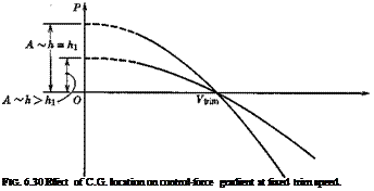
Подпись: FIG. 6.30 Effect of C.G. location on control-force gradient at fixed trim speed.

It was pointed out in See. 6.7 how the trim tabs can he used to reduce the stick force to zero. A significant handling characteristic is the gradient of P with F at P = 0. The manner in which this changes as the C. G. is moved aft is illustrated in Fig. 6.30. The trim tab is assumed to be set so as to keep Ftrim the same. The gradient dP/dV is seen to decrease in magnitude as the C. G.

moves backward. When it is at the control-free neutral point, A = 0 for aircraft with or without tails, and, under the stated conditions, the P—F graph becomes a straight line lying on the F axis. This is an important characteristic of the control-free N. P.; i. e. when the C. G. is at that point, no force is required to change the trim speed.

A quantitative analysis of the control-force gradient follows.

The force is given by (6.8,9). From it we obtain the derivative

Подпись:= BPV

At the speed Ftrim, P = 0, and В = —A/%pV2tIim, whence

Подпись:dP _ 2 A

dV~ Ftrim

CONTROL FORCE GRADIENT Подпись: (h - K) Подпись: (6.9,2)

A is given following (6.8,9). Substituting the value into (6.9,1) we get

From (6.9,2) we deduce the following:

1. The control-force gradient is proportional to Sece; i. e. to the cube of airplane size.

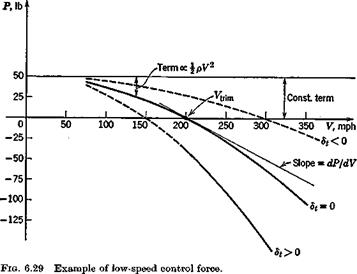
2. It is inversely proportional to the trim speed; i. e. it increases with decreasing speed. This effect is also evident in Fig. 6.29.

3. It is directly proportional to wing loading.

4. It is independent of height for a given true speed, but decreases with height for a fixed Ге-

5. It is directly proportional to the control-free static margin.

Thus, in the absence of compressibility, the elevator control will be “heaviest” at sea-level, low-speed, forward C. G. and maximum weight.

CONTROL FORCE TO TRIM

One of the important handling characteristics of an airplane is the force required of the pilot to hold the elevator at the angle required for trim, and the manner in which this force varies with speed. If friction in the control system be neglected, the stick force is simply related to the elevator hinge moment. The hinge moment itself, as can be deduced from the definition of Che is roughly proportional to the square of the speed, and the cube of the airplane size. Large high-speed airplanes therefore have serious control problems, since the forces required may be too large for a human pilot to supply. Much development has gone into attempts to arrive at purely aerodynamic solutions to this difficulty. The devices employed include various forms of nose balance, and the use of geared and spring tabs. Closely balanced controls have experienced difficulties because of the sensitivity of the hinge moment to such factors as nose shape and gap, which are inevitably subject to variations in manufacture.

Another approach is to relieve the pilot of some or all of the aerodynamic load through the use of power controls. These may be designed so that the pilot supplies a fixed proportion of the control force, the power system supplying the remainder. A system of this kind is illustrated in Fig. 11.4. With such “ratio”-type controls, the feel has the same character as when power is absent, i. e. the stick forces vary with speed, and in maneuvers, in the same way. Alternatively, the power controls may be irreversible, in that none of the aerodynamic load is carried directly to the pilot. Such systems are fitted with devices that produce a synthetic feel at the stick. The stick-force characteristics can then be made virtually whatever the designer wishes. Other classes of control system provide the pilot with power amplification rather than force amplification, i. e. the power system acts so as to increase the control deflection above that which would follow from the unpowered kinematics. This has the same net effect as the ratio-type control, however, since a greater mechanical advantage can then be supplied to the pilot than would be possible without the power boost. A detailed discussion of a variety of control concepts and mechanisms is given by Kolk (ref. 6.11), to which the student is recommended.

Control-system

CONTROL FORCE TO TRIM

CONTROL FORCE TO TRIM

linkage

Pig. 6.28 Schematic diagram of an elevator control system.

Подпись: or CONTROL FORCE TO TRIM Подпись: (6.8,1)

Figure 6.28 is a schematic representation of a reversible control system. The box denoted “control system linkage” represents any assemblage of levers, rods, pulleys, cables, and power-boost elements that comprise a general control system. We assume that the elements of the linkage and the structure to which it is attached are ideally rigid, so that no strain energy is stored in them. We also neglect friction, and assume that the movement of the control is slow enough that the automatic power elements have nearly zero error (e. g. the link AB in Fig. 11.4 does not rotate appreciably). The system then has one degree of freedom. P is the force applied by the pilot, (positive to the rear) s is the displacement of the hand grip, and the work done by the power boost system is Wb. Considering a small quasistatic displacement from equilibrium (i. e. no kinetic energy appears in the control system), conservation of energy gives

Now the nature of ratio or power boost controls is such that dWJds is proportional to P or He. Hence we can write

Подпись:Р = (ві~

ds

where 6ri = — —2 > 0, the elevator gearing (rad/ft)

CONTROL FORCE TO TRIMand

In the example of Fig. 11.4, Oj is zero in a steady state, and clearly the work done by the hydraulic system is dWb = const X J ds, where the constant derives from the various lever ratios; and J = const X He. Hence dWJd. s = const X He. The latter constant, easily found from the geometry, is G2. Finally, we write

P = GHe (6.8,3)

where G — С?! — G2. For fixed Gt, i. e. for a given movement of the control surface to result from a given displacement of the pilot’s control, then the introduction of power boost is seen to reduce G and hence P. G may be designed to be constant over the whole range of de, or it may, by the use of special linkages and power systems, be made variable in almost any desired manner.

Introduction of the hinge-moment coefficient gives the expression for P as

P = GChe8MpV2 (6-8,4)

and the variation of P with flight speed depends on both V2 and on how Ghe

varies with speed.

The value of Ghl at trim for arbitrary tab angle is given by

Che = @he о + ^fteaatrim + Metrim + (6.8,5)

From (6.7,1) we see that

Che=h(dt-d4tJ (6.8,6)

i. e. the hinge moment is zero when 6t = <5itrim as expected, and linearly proportional to the difference. From (6.7,2) then the hinge moment is

CONTROL FORCE TO TRIM

Che = M, + Cb, + (CheCr – b/Jr) -°^(h – K)CLmm (6.8,7)

where w = W/S, the “wing loading.” When (6.8,7 and 8) are substituted into (6.8,4) the result obtained is

Подпись: (6.8,9)Подпись:P = A + B^pV2

A = – G8ecew ^ (h – K)

Д

В = GSece[bA + 6’i<!o + (CheCLs – b2CLJ

CONTROL FORCE TO TRIM

The typical parabolic variation of P with V when the aerodynamic coefficients are all constant, is shown in Fig. 6.29. The following conclusions may be drawn.

SERVO TABS

When the pilot’s control force acts only to deflect the tab, and not the main surface, it is designated a servo tab. This result is attained if the torsion spring of Fig. 6.27 is replaced by a free hinge. The control lever then becomes an idler and the force in the control rod is simply the reaction to the tab hinge moment, which is of course relatively small. The angle through which the control surface deflects is then governed by the kinematics of the linkage,

and the equilibrium of aerodynamic and control rod moments about the main surface hinge.

Both spring tabs and servo tabs are effective devices for reducing control forces on large high-speed airplanes. However, both add an additional degree of freedom to the control system dynamics, and this is a potential source of trouble due to vibration or flutter.

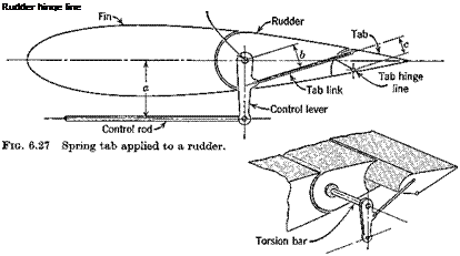
SPRING TABS

The effect of the “speed-squared law” on control forces at high speeds has led to the development of the “spring tab.” The effect of this device is to

Подпись: Rudder hinge line

mitigate the influence of speed. Figure 6.27 shows the principle. The system functions as follows. When a force is applied through the control rod to the control lever, the latter rotates through some angle 6. The control surface would rotate through the same angle, and the tab not move at all, if the control lever were rigidly connected to the surface. However, this is not so, and the torsion bar twists through some angle ф. The surface displacement is then д = в — ф. The movement of the control lever relative to the surface (angle ф), causes the tab link to move and deflect the tab, just as though it were a geared tab. Now with all other factors equal, an increase in speed will require an increase in the control-rod load to hold the same surface angle. But an increase in this force introduces extra twist into the torsion bar, and hence increases the tab deflection. Thus, as the speed increases, an increasing proportion of the hinge moment is balanced by the tab, and a decreasing proportion by the pilot or control system. In effect, the system behaves like a geared servo tab, the gearing of which increases with speed.

GEARED TABS

The coefficient 62 dominates the hinge moment of a control, and hence the control force. It gives the rate at which the hinge moment increases with
control angle. The need for reduction of b2 by aerodynamic means was referred to in Sec. 6.5. One such means, which is very effective, is the geared or servo tab. The geometry of such a tab is illustrated in Fig. 6.26. The angle of the tab relative to the control surface is determined by the rigid link AB. When arranged as shown, downward movement of the control is accompanied by an automatic upward movement of the tab. The hinge moment caused by the tab is then of the sense which assists the control movement. If В were moved to the upper surface of the tab, so that AB crossed HH, then the opposite effect would be obtained. This arrangement, known as an antiservo, or antibalance tab can be used when a control is otherwise overbalanced, or too closely balanced. It provides a means of achieving a zero or positive b1 without any detrimental effect on b2, as follows. The balance, cb (Fig, 6.21), is chosen large enough so that bx becomes zero or positive. The control will then have b2 either too small or even positive. This is then corrected by introducing an antiservo geared tab.

Suppose that, when the elevator moves through an angle 8e, the tab displacement is — yde. y, called the “tab gearing,” is positive for a servo tab and negative for an antiservo tab. The hinge-moment coefficient will then be

Che — b0 + bjo+ b2de + b38t

GEARED TABS

GEARED TABS

(6.7,6)

GEARED TABS

The servo tab thus in effect reduces the value of b2 by the factor

THE USE OF TABS

TRIM TABS

In order to fly at a given speed, or CL, it has been shown in Sec. 6.4 that a certain elevator angle detrlm is required. When this differs from the free- floating angle <5efree, a force is required to hold the elevator. When flying for long periods at a constant speed, it is very fatiguing for the pilot to maintain such a force. The trim tabs are used to relieve the pilot of this load by causing d and <5efree to coincide. The trim-tab angle required is calculated below.

When Che and Cm are both zero, the tab angle is obtained from (6.5,2) as ^trim = — T trim + Metrim) (6-7,1)

°3

On substituting from (6.4,13), (which implies neglecting dCmlddt) we get = – £ [e*.. + °-f – b2CLJ + ^ (GheCms – 62Cma)j

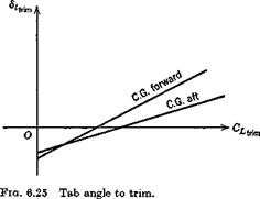
which is linear in Cxtrim for constant h, as shown in Fig. 6.25. The dependence on h is simple, since from (6.6,11) we find that

– hCmJ = -a(h – K)

and hence

Подпись: (6.7,2)= “ [<k. + ~ ~ b*GiJ ~ – K)cLtrim

This result apphes to both tailed and tailless aircraft, provided only that the appropriate values of the coefficients are used. It should be realized, of course, in reference to Fig. 6.25, that each different C£trlm, n a real flight situation corresponds to a different set of values of M, JpF2, and CT, so that in general the coefficients of (6.7,2) vary with CL, and the graphs will depart from straight lines.

Подпись:Equation (6.7,2) shows that the slope of the <5( vs GL curve is pro­portional to the control-free static margin. When the coefficients are constants, we have

Подпись: (6.7,3)

THE USE OF TABS

b, Д

The similarity between (6.7,3) and (6.4,13c) is noteworthy, i. e. the trim-tab slope bears the same relation to the control-free N. P. as the elevator angle slope does to the control-fixed N. P. It follows that flight determination of h’n from measurements of ddt^^JdCj is possible subject to the same

restrictions as discussed in relation to the measurement of hn on p. 221.

CONTROL-FREE NEUTRAL POINT

CONTROL-FREE NEUTRAL POINT Подпись: (6.6,10)

It is evident from the preceding comment that the N. P. of a tailed aircraft when the control is free is given by (6.3,36) as

Подпись: or CONTROL-FREE NEUTRAL POINT CONTROL-FREE NEUTRAL POINT Подпись: (6.6,11)

Alternatively, we can derive the N. P. location from (6.6,56), for we know from (6.3,19) that

Since Gmg is of different form for the two main types of aircraft, we proceed separately below.

CONTROL-FREE NEUTRAL POINT

Tailless Aircraft. Gmg is given by (6.4,9) and Chex = bv When these are substituted into (6.6,11) the result is

A, dde

Подпись: or CONTROL-FREE NEUTRAL POINT Подпись: (6.6,12)

By virtue of (6.6,6) this becomes

Tailed Aircraft. Cm is given by (6.4,8), so (6.6,11) becomes for this case

(h – Ъ’п) = – (Ь – K) – °^CLs(h – hnJ + aeVH a ab2 a’b2

Using (6.6,46) this becomes

h-h’n = h-~ iahn – h + ^faeVH

a’ b2 “7 a’62

CONTROL-FREE NEUTRAL POINT

We replace hnwb by (hnab – hn) + hn to get

Finally, using (6.4,8) for CL&, and (6.5,4) for Ghv we get

Подпись: (6.6,13)

The difference (h! n — h) is called the control-free static margin, K’„. When representative numerical values are used in (6.6,13) one finds that hn — h’n may be typically about 0.08. This represents a substantial forward movement of the N. P., with consequent reduction of static margin, pitch stiffness, and stability.

FREE-ELEVATOR FACTOR

FREE-ELEVATOR FACTOR

When the elevator is part of the wing, as on a tailless aircraft, and the elevator is free, the lift-curve slope is given by (6.6,46), i. e.

Подпись: or Подпись: (6.6,7)
FREE-ELEVATOR FACTOR

The factor in parentheses is the free elevator factor F, and normally has a value less than unity. Likewise, when the elevator is part of the tail, the floating angle can be related to a„ viz.

FREE-ELEVATOR FACTOR

and the tail lift coefficient is

FREE-ELEVATOR FACTOR(6.6,8)

FREE-ELEVATOR FACTOR

The effective lift-curve slope is

place of at and a’ in place of a, then all the equations given in Sec. 6.3 hold for tailed aircraft with a free elevator.