Category Dynamics of. Atmospheric Flight

PITCH STIFFNESS OF A GENERAL CONFIGURATION

Having established above the central importance of the derivative C for satisfactory flight, we turn now to a detailed discussion of it for a general vehicle configuration. We consider the vehicle to be composed of a body, a wing, a tail and propulsive units. If any of these are absent (as for a tailless airplane, a wingless missile, or a glider) the appropriate deletions from the analysis are readily made.

The pressure distribution over the surfaces of a vehicle in steady rectilinear motion, and the consequent integrated forces and moments, are functions of angle of attack a, control surface angles, Mach number M, Reynolds number Re, thrust coefficient CT, and dynamic pressure pV2. The last-mentioned parameter enters because of aeroelastic effects. If the vehicle is flexible, then a change in dynamic pressure, with all other variables constant, produces a change in shape, and hence of the forces and moments.

In the following discussion the only restriction in relation to the above parameters is that of steady rectilinear flight. Specifically, power effects, flexibility, and compressibility effects are not excluded.

PITCHING MOMENT OF A WING

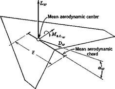
The force system acting on an isolated wing, in symmetric flight, can be represented as a lift Lw and drag ])w acting at a reference point, the mean aerodynamic center, together with a pitching moment Ma c (Fig. 6.7).

PITCH STIFFNESS OF A GENERAL CONFIGURATION

Fig. 6.7 Aerodynamic forces on the wing.

PITCH STIFFNESS OF A GENERAL CONFIGURATION

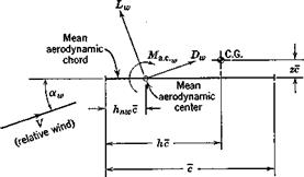
Fig. 6.8 Moment about the C. G. in the plane of symmetry.

The inviscid theory of thin wings at small aw predicts that the moment about the aerodynamic center is invariant with aw, and this is indeed very often the case in reality. However, it is possible that „ may vary with aw, and this case is included in the following. The moment of the force system of Fig. 6.7 about the vehicle center of gravity (see Fig. 6.8) is given by

= – Ma. c.„ + (Lw cos ocw + Dw sin am)(h – hnJc

+ (La sin a„ – Dw cos xjzc (6.3Д)

For many flight situations, including the cruising flight of all classes of fixed-wing aircraft, the angle of attack is small enough to justify the approximations sin am = aw, cos aw = 1. We take this to be the case here, bearing in mind the consequent restriction on the validity of the resulting equations.

Equation (6.3,1) is made nondimensional by dividing through by %pV2Sc. It then becomes

Cmw = ^ma. c.„, + ^Dwaw)(^ — У + — CDf)z (6.3,2)

Although it may occasionally be necessary to retain all the terms in (6.3,2), experience has shown that the last one is frequently negligible, and that Gnjy. w may often be neglected in comparison with CLw. With these simpli­fications, we obtain

Ста = Стлс +CLJh-hnJ (6.3,3)

* ‘to

Equation (6.3,3) will be used to represent the wing pitching moment in the discussions that follow.

PITCH STIFFNESS AND POSSIBLE CONFIGURATIONS FOR FLIGHT

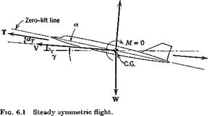
In Fig. 6.1 we have shown that the pitching moment M is zero, which is, of course, one of the conditions for equilibrium. It is intuitively evident, without recourse to any formal stability theory, that there might be some­thing wrong with a flight vehicle that at constant speed and with fixed controls, experienced a positive (nose-up) pitching moment ACm following an increase Да in the angle of attack from its equilibrium value. This is illustrated in curve a of Fig. 6.3 (i. e. Cmx > 0). For then the moment AC’TO

PITCH STIFFNESS AND POSSIBLE CONFIGURATIONS FOR FLIGHT

Fig. 6.3 Pitch stiffness.

would be such as to increase further the perturbation in a. On the other hand, if the Cm vs a relation is as in curve b, {Oma < 0) the moment following the disturbance is negative, and tends to restore a to its equilibrium value. The latter case is exactly parallel to that of a mass on a spring, which when disturbed from equilibrium, experiences a restoring force. The vehicle possesses as it were an “aerodynamic torsion spring” that tries to hold а constant at its equilibrium value. This property has traditionally been called “static stability” in pitch. In view of the more formal, more precise meaning now usually attached to the word stability (see Chapter 3), a more appropriate designation is positive pitch stiffness. The complete stability theory of the longitudinal motion (see Chapter 9) shows that positive pitch stiffness (Gm < 0) is in general neither necessary nor sufficient for stability. However, it is nevertheless a very important practical design criterion, the violation of which leads to consequences that can rarely be tolerated. The great importance of pitch stiffness makes calculation or measurement of Cm(a) one of the central features of the aerodynamic design of all flight vehicles. This curve is typically monotonic in a over the usable flight range, as in Fig. 6.3, curve b.

We may conclude then, that a satisfactory flight configuration must not only have Gm = 0 at some a > 0 in order to trim (i. e. be in pitch equilibrium) at positive lift, but at the same time must usually have Gm < 0. Alternatively, as can be seen from Fig. 6.3, it must have (7TOo > 0 and (7 < 0. It is

somewhat simpler to use the latter form of the criterion to assess the possibilities for flight.

We state here without proof (this is given in Sec. 6.3) that dCmlda can be made negative for virtually any combination of lifting surfaces and bodies by placing the center of gravity far enough forward. Thus it is not the stiffness requirement, taken by itself, that restricts the possible configurations, but rather that it must coexist with zero moment. Since a proper choice of the C. G. location can ensure a negative ЭС^/Зк, then any configuration with a positive Cmo can satisfy the conditions for flight at L > 0.

Figure 6.4 shows the Cma of conventional airfoil sections. If an airplane were

PITCH STIFFNESS AND POSSIBLE CONFIGURATIONS FOR FLIGHT

Positive camber Zero camber Negative camber

Cm„ negative Cm0 = 0 cm0 positive

Fig. 6.4 Cmo of airfoil sections.

to consist of a straight wing alone (flying wing), then the wing camber would determine the airplane characteristics as follows:

Negative camber—flight possible at a > 0; i. e. CL > 0.

Zero camber—flight possible only at a = 0, or CL = 0.

Positive camber—flight not possible at any positive a or 0L.

For straight-winged tailless airplanes, only the negative camber satisfies the conditions for flight. Effectively the same result is attained if a flap, deflected upward, is incorporated at the trailing edge of a symmetrical airfoil. A conventional low-speed airplane, with essentially straight wings and positive camber, could fly upside down without a tail, provided the C. G. were far enough forward. The positively cambered straight wing can be used only in conjunction with an auxiliary device which provides the positive Cmo. The solution adopted by experimenters as far back as Samuel Henson (1842) and John Stringfellow (1848) was to add a tail behind the wing. The Wright brothers (1903) used a tail ahead of the wing (Canard configuration). Either of these alternatives can supply a positive Cmo as illustrated in Fig. 6.5. When the wing is at zero lift, the auxiliary surface must provide a nose-up

PITCH STIFFNESS AND POSSIBLE CONFIGURATIONS FOR FLIGHT

Tail with + Cambered wing at

CL positive CL = 0

(b)

Fig. 6.5 Wing-tail arrangements with positive (7mo. (a) Conventional arrangement. (6) Tail-first or Canard arrangement.

moment. The conventional tail must therefore be at a negative angle of attack, and the Canard tail at a positive angle.

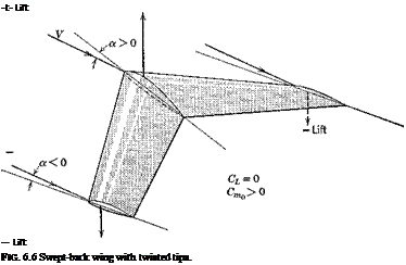
Подпись: -t- Lift — Lift FIG. 6.6 Swept-back wing with twisted tips.

An alternative to the wing-tail combination is the swept-back wing with twisted tips (Fig. 6.6). When the net lift is zero, the forward part of the wing has positive lift, and the rear part negative. The result is a positive couple, as desired.

A variant of the swept-back wing is the delta wing. The positive Gm<) can be achieved with such planforms by twisting the tips, by employing negative camber, or by incorporating an upturned tailing edge flap.

THE BASIC LONGITUDINAL FORCES

The basic flight condition for most vehicles is symmetric steady flight. In this condition the velocity and force vectors are as illustrated in Fig. 6.1.

L

THE BASIC LONGITUDINAL FORCES

The steady-state condition was fully described in Sec. 5.9. All the nonzero forces and motion variables are members of the set defined as “longitudinal” in Chapter 5, and hence we see the central importance of longitudinal aerodynamics. The two main aerodynamic parameters of this condition are

V and a.

Nothing can be said in general about the way the thrust vector varies with

V and a, since it is so dependent on the type of propulsion unit—rockets, jet, propeller, or prop-jet. Two particular idealizations are of interest, however,

(i) T independent of V, i. e. constant thrust; an approximation for rockets and pure jets.

(ii) TV independent of V, i. e. constant power; an approximation for reciprocating engines with constant-speed propellers.

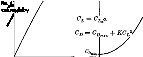
The variation of steady-state lift and drag with a for subsonic and supersonic Mach numbers (M < about 5) are characteristically as shown in Fig. 6.2 for the range of attached flow over the surfaces of the vehicle (refs. 6.5, 6.6). Over a useful range of к (below the stall) the coefficients are given accurately

THE BASIC LONGITUDINAL FORCES
Подпись: (6.1,2)
Подпись: ■a
Подпись: (в.ід)

The three constants Gl* CnmiI , К are principally functions of the con­figuration shape, thrust coefficient, and Mach number.

Significant departure from the above idealizations may, of course, he anticipated in some cases. The minimum of CD may occur at a value of a > 0, and the curvature of the CL vs. a relation may be an important consideration for flight at high CL. When the vehicle is a “slender body,” e. g. a slender delta, or a slim wingless body, the CL curve may have a characteristic upward curvature even at small a (ref. 6.7). The upward curvature of CL at small a is inherently present at hypersonic Mach numbers (ref. 6.8). For the nonlinear cases, a suitable formulation for CL is (ref. 6.9)

Gl = UCn. sin 2a + CNaa sin a |sin a|) cos a (6.1,3)

where CNa and GNaa are coefficients (independent of a) that depend on the Mach number and configuration. [Actually CN here is the coefficient of the aerodynamic force component normal to the wing chord, and CN is the value of CLa at a = 0, as can easily be seen by linearizing (6.1,3) with respect to a.] Equation (6.1,2) for the drag coefficient can serve quite well for flight dynamics applications up to hypersonic speeds (M > 5) at which theory indicates that the exponent of CL decreases from 2 to ■§. Miele (ref. 6.10) presents in Chapter 6 a very useful and instructive set of typical lift and drag data for a wide range of vehicle types, from subsonic to hypersonic.

Longitudinal aerodynamic characteristics—part 1

In the preceding chapters we have presented the general analytical foundations for solving problems concerning the motion of flight vehicles in the atmosphere. As was emphasized, however, the details of the problems and the character of the results obtained are dominated by the aerodynamic characteristics of the vehicle. It is essential therefore to explore the aero­dynamic aspect of the subject in some depth before proceeding to particular studies of vehicle dynamics. To this end, this and the following two chapters are devoted to a discussion of the main aerodynamic features of flight vehicles that are of concern for vehicle motion. Included is a body of material, traditionally referred to as “static stability and control” that relates to the control displacements and forces required to maintain steady rectilinear flight, or to maintain a steady “pull-up.” These are important items, both in relation to handling qualities and to their use as stability criteria. Clearly the spectrum of vehicle types and operating conditions of interest is extremely broad—from air-cushion vehicles and helicopters on the one hand to hyper­sonic aircraft and entry vehicles on the other. It is obviously not practical to present a comprehensive coverage of the aerodynamics of all these types within the scope of this text. The items selected for treatment are those considered to be particularly instructive and of rather broad application. With this basis it is hoped that the reader should be able to extrapolate the methods and approaches presented to other situations with which he may be
concerned. One topic completely excluded, because it requires an extensive treatment to be meaningful at all, is the aerodynamic characteristics of rotorcraft. References 6.1 to 6.4 give considerable information on this and other relevant topics in aerodynamics.

FURTHER ASSUMPTIONS

In the classical linear equations, m and g are constants, the vehicle is assumed to have a plane of symmetry, and the momenta of spinning rotors is excluded. The latter assumption is easily relaxed when rotor terms are important. As a particular choice for body axes we select Fs, the stability axes, for which a. Xf = we = 0 (see Sec. 4.2.7). Since the initial heading has no special significance in the flat-Earth approximation, we also set y>w = 0.

Instead of a. x, the angle of attack of the xs axis, we choose for the angle of attack variable that of the zero lift line (see Sec. 6.1). It is denoted simply a, and of course is not zero in the reference state, a and otx differ only by a constant in any particular ease.

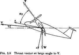
In treating the thrust terms of (5.8,1) we wish to make allowance for rather general conditions, such as can occur in VTOL and STOL flight, when the thrust vector may be at large angles to the direction of motion. We therefore assume conditions as illustrated in Fig. 5.8. We further assume that the thrust vector rotates rigidly with the vehicle when it is perturbed. This implies that any rotation of the thrust relative to the vehicle is to be accounted for by adding suitable increments to L, D, and Y.

In the perturbed state, the thrust vector in body axes is

’ cos a. T ‘

Подпись: 0Подпись:TB = (Te + A T)

and in the wind axes is

Tjjr — LWBTB

On making use of (4.5,5) (with atx = Да therein) and linearizing, the result is

Подпись:

FURTHER ASSUMPTIONS

TXw = (Te + AT) cos a. T — Aa. Te sin a. T (a) Tvw = – PTe cos aT (6)

TZW= — (Te + AT)sinct. T — Aa^cosay (c)

THE LINEAR EQUATIONS

In linearizing the appropriate members of (5.8,1) to (5.8,7), we assume that all the perturbation quantities AF, Да, p, etc., are small, and that squares and products of them may be neglected. It follows that cos Ау 1,

and sin Aу = Ay. Thus (5.8,1a) for example becomes

(Te + AT) cos a. T — ActTe sin аг — (De + AD) — mg sin (ye + Ay) = mt

or, on expanding the trigonometric term,

(Te cos xT — De — mg sin ye) + AT cos аг

— ДаTe sin ат — AD — mg cos уe Ay — mV

The part in brackets vanishes, since the reference state must satisfy the equations, and hence the final perturbation equation is

AT cos a. T — ДаTe sin olt — AD — mg cos ye Ay — mV (5.10,4)

Note that no approximation has been made here concerning ye. The equation applies to flight at any angle of climb or descent up to vertical flight. Pro­ceeding in a similar manner for all the other equations, the result is

AT cos а у — Да Te sin а у — AD — mg cos ye A у = mV

(a)

AY + mg cos уеф = m(v + Ver)

(b)

(5.10,5)

AT sin а у + Аа Te cos а у + A L + mg sin

ye Ay = mVeqw

(o)

AT Ixp Tzxr

(a)

AM = Iyq

(&)

(5.10,6)

AN = Izr – Izxp

(c)

ф = p + r tan yt

, («)t

Y = 4w

Ф)

(5.10,7)

ip = r sec ye

(o)t

II

1

(5.10,8)

*E = Ve cos Ye + COS ye AV –

vesin Ye Ay

(a)

Уе = Ve COS ye ■ ip + V

(b)

(5.10,9)J

zE= – Fesinye – siny„AF-

– Ve cos ye Ay

(o)

Note that the order of the terms in (5.10,8) has been rearranged slightly as compared with (5.8,5) and that two of the latter are not needed. Of

(5.10,9) the first and third come from (5.8,6), and the second from (5.8,7).

Although the moment equations (5.10,6) were obtained by a linearization of (5.8,3), which are the equations for a rigid body, they are in fact valid for a deformable body. This is because the first term on the r. h.s. of (5.6,8) contains only the products of first-order rotations and rates of change of inertia coefficients. The latter are also first order in the linear model, and hence the distortional coupling terms are second order and negligible.

Because of the simplicity of the linear kinematical relations, it is convenient to eliminate qw and to regroup the equations as follows.

f Equations (5.10,7a – and c) cannot be regarded as a small-perturbation equation when ye —► ±90° for then <j> and ф -> oo for any finite r.

t Equations (5.10,9) are not strictly perturbation equations, albeit linear, because of the presence of the constant terms Ve cos ye and — Ve sin ye. The perturbations are strictly (xE – Ve cos ye), yE, and (zE + Ve sin ye).

CHOICE OF AXES

A convenient choice for the axes in the small-disturbance model is to use wind axes for the lift-force and drag-force equations (5.8,1a and c), and body axes for the remaining force and moment equations (5.8,26 and 5.8,3). For vehicles having a plane of symmetry two sets of uncoupled equations are found, the longitudinal and the lateral. Since the pitching moment equation turns out to be the same in both axis systems, the longitudinal equations are then in wind axes, and the lateral in body axes.

NOTATION FOR SMALL DISTURBANCES

The reference steady state is taken to be symmetric rectilinear flight, although the more general case can readily be handled by the same approach

(ref. 6.3). The steady-state values are denoted by subscript e (for equilibrium) and changes from them by the prefix A. Thus for example

V = Ve + AV

ф — фе + Аф

P = pe + Ap (5.10,1)

L = Le + AL
etc.

Since the steady state selected is wings-level translation, we can have at most the following nonzero reference values of the state variables:

Ve’xxe’®we’V’we (5.10,2)

All other motion and angle variables are zero in the reference state and for these the prefix A is not needed. QWe as well will be zero if the reference state is horizontal flight, as it must be when we include the variation of air density with height. However, we keep as nonzero in order to include the case of constant density within the analysis. 6W, the angle of climb, is replaced with the more common symbol y.

THE SMALL-DISTURBANCE THEORY

A particular form of the system equations that has been used with enor­mous success ever since the beginnings of this subject is the linearized model for small disturbances about a reference condition of steady rectilinear flight over a flat Earth. This theory yields much valuable information and many important insights with relatively little effort. It gives correct enough results for engineering purposes over a surprisingly wide range of appli­cations, including stability and control response. There are, of course, limitations. It is not suitable for spinning, post-stall gyrations, nor any other application in which large variations occur in the state variables.

The reasons for the relative success of this approach are twofold: (i) in many cases the major aerodynamic effects are truly nearly linear functions of the state variables, and (ii) disturbed flight of considerable violence can correspond to relatively small values of the linear – and angular-velocity disturbances.

STEADY STATES

It is of interest to deduce from the preceding general equations what “equilibrium points” exist for a flight vehicle. Neglecting motion of the Earth center, a true state of rest in inertial space occurs only when the vehicle travels due west at a rate exactly equal to that of the local eastward motion of the Earth. This is too restricted a case to be useful. Equilibrium in a more general dynamical sense corresponds to equilibrium of all the external forces, i. e. a state of zero acceleration, or rectilinear motion. On a round Earth, this kind of equilibrium is also not useful, since the flight path would then either intersect the Earth, or go off into space. The useful definition is that of an “aerodynamic steady state,” in which the motion, the aero­dynamic field, and gravity are all constant in the frame FB. Thus the aero­dynamic pressure distribution and the gravity components are constant with time. Such a state requires, first, that (u, v, w) or (F, otx, fl) and the rates of rotation (со — a>E)B of FB relative to the atmosphere or to FE be constants. Second, the Euler angles в, <j> that affect the gravity components must be constant. Constancy of aerodynamic forces at constant (V, ax, /1) also re­quires constant air density, i. e. constant altitude flight. Thus 0W = 0. Now consider the force equation (5.6,2). By postulate, the derivative terms are zero, and the left-hand side is constant. It follows that these equations can be solved for the constant values of

Подпись: (wE +&>)B —P B+P йХв + Я rEB + r_

Since the sum and difference (line 14 above) of ыЕв and <aB are constants, then they must be separately constant. Since (a, fl) and (p, q, r) are constants, then from (5.2,13), (pw, qw, rw) are also constant, and transforming the constant ыЕв into Fw leads to a constant <aBw. Now the components of шЕ can be constant in Fw and/or FB, with the constraint of constant altitude, only if the motion of the frame is a rigid-body rotation around the Earth’s axis. Thus the path of the vehicle mass center must be a circle around the axis, i. e. it must be a minor circle of the Earth, lying on a parallel of latitude. Analyti­cally this means that X = const, and y> = ±7t/2. The conditions for this most general steady state may then be summarized as follows, taking the

STEADY STATES
Подпись: (5.9,1)
STEADY STATES

The wind-axis force equations (5.5,8) then reduce to

TVw — G + mg sin </>w = —mV sin (A — ^TF)(2coE + /і) (5.9,6)

TZw — L+ mg cos <j>w = mV cos (A — </>w)(2coE + /і)

The reduced moment equations for this case are of little interest, since they contain only second-degree terms in (p, q, r), and the latter are clearly of order (ooE + ft), which is at most about 10~3 rad/sec for suborbital flight. They therefore reduce to L = M = N = 0.

To be exact, even this restricted steady state cannot exist, for the following reasons:

(i) All real vehicles in horizontal flight have propulsion systems that utilize fuel, so m is never strictly constant.

(ii) The Earth is not a perfect sphere, so that flight at constant altitude (i. e. air density) is not strictly flight on a circle.

(iii) The atmospheric density is never exactly constant and the wind never exactly zero at a given height.

These deviations from the idealized steady state are, of course, not im­portant enough to invalidate its usefulness.

If the Earth rotation ыЕ can be neglected, then clearly no one minor circle is preferable to any other, and the steady state can be on any minor circle over the Earth. In the flat-Earth approximation, the minor circle becomes any circle parallel to the ground surface. If in addition the variation of p with height can be neglected, as for a shallow climb or glide, the most general steady state becomes a vertical helix, i. e. a climbing or gliding turn.

THE FLAT-EARTH APPROXIMATION

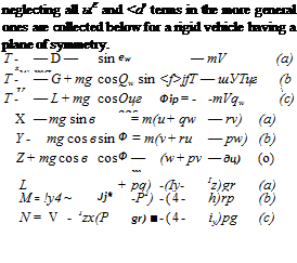
We have shown above that a wide and important range of flight dynamics problems, corresponding roughly to M < 3, can be treated adequately with a significantly simpler mathematical model than that given in Figs. 5.4 and 5.5—that is, by neglecting w® and ojf or alternatively by treating the Earth as a stationary plane in inertial space. The reduced equations obtained by

{]>———– и

Подпись: й v w Подпись: ЯЕв гЕв THE FLAT-EARTH APPROXIMATIONПодпись: P q r Ф в Ф P Q R к A зі fl>——- »

Ф——— w

■Q>—– p

{t>——- 9

0>——– r

{$>– <t>

——- *

Ф——– *

{E>—– x

{D—— m

Ф——– 6

Fig. 5.5 Block diagram of equations for rigid vehicle. Spherical rotating earth. Body axis system.

Подпись: neglecting all ыЕ and <av terms in the more general ones are collected below for a rigid vehicle having a plane of symmetry. T - xw — D — mg sin ew — mV (a) T - Vw — G + mg cos Qw sin <f>jfT — шУТцг (b) T - — L + mg cos Оцг cos Фір = - -mVqw (c) X - — mg sin в = m(u + qw — rv) (a) Y - mg cos в sin Ф = m(v + ru — pw) (b) Z + mg cos в cos Ф — m (w + pv — дц) (o) L + pq) -(Iy- Iz)gr (a) M = !y4 ~ Jj* -P2) -(4- h)rp (b) N = V - Izx(P gr) ■ -(4- iy)pg (c) (5.8,1)

(5-8,2)

(5.8,3)

~ p if – ~f~ qic sin фц – tan Оц – – j – Tjy cos фц – tan 0jy – (a)

0 fj – = i/ff – cos ф f і – )’ц – sin </)[(‘ (b) (6.8,4)

(pjy ==: (//jj■ sin фц – – f – ( cos фц) sec Off – (c)

(Without subscript W, (5.8,4) apply to body axes.)

ax = q — qw sec ft — p cos a. x tan ft — r sin ax tan ft (a)

P = rw + P sin otx — r cos otx (b) (5.8,5)

pw = p cos іxx cos /3 + (q — ax) sin |S + r sin ax cos /3 (c)

xE=V cos 0W cos y)w (a)

yE= V cos dw sin ipw (6) (5.8,6)

ZE = —V sin 6W (c)

Xjf ~u

УЕ = I’fb ® (5-8,7)

[w

THE FLAT-EARTH APPROXIMATION THE FLAT-EARTH APPROXIMATION THE FLAT-EARTH APPROXIMATION

Following traditional usage, £ is used above as a symbol for both lift force and rolling moment. The context usually makes it quite clear which

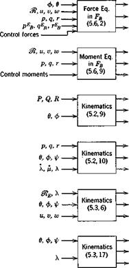
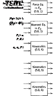
Fig. 5.6 Block diagram of equations for rigid vehicle with plane of symmetry. Combined wind and body axes. Flat-Earth approximation.

{D——- «

Подпись: 9, ф zE,u,v,w p.g.r Control forces Подпись: ZE, U,V,U)Подпись: p,q,r Control momentsПодпись: 9, ФПодпись: P.q.rПодпись: u, v, wПодпись: Ф, 9, фПодпись: v w Подпись: P g r Подпись: Ф в Ф *E УЕ THE FLAT-EARTH APPROXIMATION{T>—— »

——- »

■П>—– ь

{0——– g

{D>—— r

——- ф

-□>———– 9

■o>—*

"U>—————- XE

"Ц> yE

■Q>————— ZE

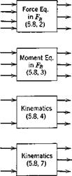
Fig. 5.7 Block diagram of equations for vehicle with plane of symmetry. Body axes. Flat-Earth approximation.

is meant, and even the novice seldom has difficulty with this ambiguity. In the nondimensional form of the equations, the ambiguity disappears, different symbols being used for the two quantities.

The block diagrams for the above equations are given in Figs. 5.6 and 5.7 for the combined and body-axes systems, respectively. Since in the case of body axes there are no kinematical relations needed to connect the two axis systems, the number of equations is twelve instead of 15. However the force equations (5.8,2) and the position equations (5.8,7) are then more complex than (5.8,1) and (5.8,6) which they replace, so the advantage resulting from the reduction of size is offset by greater complexity in the remaining members. The state variables of Figs. 5.6 and 5.7 are conveniently grouped for identi­fication as follows:

Подпись: (u, v, w) or (F, a*, /3) (P, Ъ r) (XE> УEi ZE) (ф, в, y>) (ФтР’ ®W’ fw) Подпись:give translation of vehicle relative to Earth, give rotation of vehicle relative to Earth, give position of vehicle relative to Earth axes, give angular orientation of vehicle relative to Fv.

give orientation of wind axes. 6W = у is the angle of climb, and ipw is the heading of flight path.

give angular velocity of the wind axes.

DISCUSSION OF THE SYSTEM OF EQUATIONS

We have presented in the preceding sections a large number of complicated coupled equations that describe the kinematics and dynamics of a vehicle in flight over a spherical rotating Earth. (The student may be forgiven if he is slightly bewildered by them at this point!) Our purpose here is to evaluate these equations, show the relationships between them, and present the essential structure of the system.

Much of the complexity has resulted from the inclusion of the rotation of the earth (the to® terms) and its curvature (the to® terms) in the mathe­matical model. We have already shown (Sec. 5.3) that the centripetal acceleration associated with ыЕ is usually negligible, and that the Coriolis acceleration is small but not quite negligible. To gain further insight into the to® and to® terms we look at the z component of the force equation for horizontal flight on the equator. Thus with 6W = <f>w = 0, (5.5,8c) gives

-L + TZw + mg = – mV(qEw + qw) (5.7,1)

With tpw = 90° for eastward flight and Я = 0, (5.3,14) and (4.5,4) yield

qEw = – со® (5.7,2)

Since the Euler angles are constants, then from (5.2,8) Pw — Qw — ^W — and from (5.2,10)

qw=-(mE+fi) (5.7,3)

From (5.3,5), pt = Vj&, so that finally (5.7,1) becomes

—L + TZw + mg = mV^2wE +

Подпись: — 2mV(oE +Подпись: (5.7,4)mV2

The first term on the r. h.s. is the Coriolis force due to Earth rotation, and when V equals orbital speed (about 26,000 fps) amounts to about mg. The second term is due to Earth curvature (in the “flat” Earth approxi­mation 0t = oo and this term vanishes), and at orbital speed makes up the balance, about 90 %, of mg. [Note that F is speed relative to not relative to Fj, and that the exact form of (5.7,4) would have the additional small term –тМ(ош% on the r. h.s.] Both terms on the r. h.s. of (5.7,4) increase with speed, the first linearly, the second quadratically, and each amounts to 1 % of the weight when the speed is about of orbital speed, i. e. about 2600 fps for atmospheric flight. This speed therefore seems a useful boundary below which both ыв and wF can be neglected, and above which they should be included for accurate results. It corresponds to a Mach number of about 2% to 3, depending on altitude, so that at low supersonic speeds, as for first generation supersonic transports, these terms are just marginally small— perhaps not quite negligible for range calculations. For all high supersonic speeds and hypersonic speeds they would be of increasing importance.

The preceding argument, being based on the force equation of motion, has validity only for trajectory calculations, i. e. for calculations of the flight path. When the problem of interest concerns attitude dynamics, i. e. the relatively rapid rotational motions of the vehicle relative to Fr, the situation is quite different. For then and coF can be important only if they are appreciable compared to to (greater than 1% say). Now mB m 7 x 10“5 rad/sec is extremely small compared to most technically important vehicle rotations, and wr has a maximum value at orbital speed of about 10-s rad/sec which is also negligible in this context. Hence both <aE and toF terms are normally negligible insofar as the moment equations are con­cerned.

Two alternatives have been presented for the dynamical force equations: in wind axes and body axes. Both are used in current practice, and there are no overriding advantages for either system. The wind-axes form is gener­ally more convenient for trajectory analysis, in which the attitude of the vehicle is prescribed a priori, and the moment equations are not used at all. For combined trajectory and attitude motions, either a “mixed” form of the equations, or the body-axes form, is normally employed. In hovering flight, when V — 0, and the angles oc and (j are not defined, the body-axes form is virtually mandatory. It is convenient to use a particular mixed form of the force equations for the analysis of small perturbations from a steady reference state (see Sec. 5.10).

On the other hand, there is only one reasonable choice for the moment equations. Only in FB is F constant for a rigid body. To use any other reference frame adds unnecessary complication.

Little has been said in the foregoing sections about the aerodynamic forces and moments that appear in the equations v(D, C, L, and T) in (5.5,8), (X, Y, Z) in (5.6,2), and (L, M, N) in (5.6,8). These depend on the local ambient density, the motion of the vehicle relative to the atmosphere, and on nonautonomous control inputs. Thus for a rigid vehicle, they are functions (more exactly, functionals, see Sec. 5.10) of p{&) the density, of (F, ax, /3), or (u, v, w), of (p, q, r),f and of a set of control variables. There are other ways, besides its appearance in p, in which the altitude (i. e. 1%), can occur as a nontrivial independent variable in the equations. One is when there is a wind gradient with height, e. g. WT(Sf), and another is when the vehicle flies close to the ground, so that there is a “ground eflect” on the aerodynamic field of the vehicle. In the latter case the aerodynamic forces can be very strong functions of height. A third case is when the gravitational inverse square law is included, i. e. g = g(3%). For near-orbital velocities at very high altitudes, it has been shown (ref. 5.4) that this refinement is necessary.

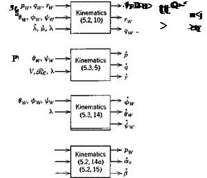
The structure of the mathematical system for a rigid vehicle (Jf = 0) in the more general high-speed case, and the interrelations among the variables, is displayed in Figs. 5.4 and 5.5. Each set of scalar equations is regarded as a subsystem that produces three dependent variables as outputs. The inputs are the quantities needed to calculate the outputs from the given equations. All the quantities shown immediately to the right of the square blocks can be found by algebraic solution of the equations. The aerodynamic terms in the force and moment equations have all been replaced by the state variables of which they are functions, and control forces and moments. On checking, the reader will find that all the autonomous variables needed as inputs on the left-hand side are available as outputs on the right-hand side.

To recapitulate, the mathematical models described by Figs. 5.4 and 5.5 are subject only to the following assumptions

(i) The Earth is a sphere rotating on an axis fixed in inertial space, and g is a radial vector.

(ii) The centripetal acceleration associated with Earth rotation is neglected.

(iii) The atmosphere is at rest relative to the Earth.

(iv) The vehicle is a rigid body.

None of these restrictions is made from any fundamental necessity, and any of them may be removed when the application requires it, at the cost of additional complexity.

t Actually the angular velocity of the vehicle relative to the atmosphere is to — to®, and it is the components of this vector, not (p, q, r), that strictly speaking should be used in the calculation of aerodynamic forces and moments. However to® is so small that in the majority of applications no significant error is incurred by neglecting it.

DISCUSSION OF THE SYSTEM OF EQUATIONS

Fig. 5.4 Block diagram of equations for rigid vehicle. Spherical rotating earth. Combined wind and body axes.