Category Dynamics of. Atmospheric Flight

FLIGHT ON ILS GLIDE SLOPE

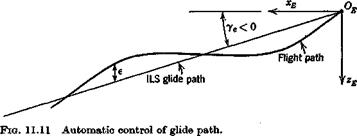
In the above analysis, we assumed that the airplane was under the control of an ideal autopilot that kept the height error exactly zero. A more realistic model incorporates a feedback control that senses height error and actu ates the elevatorf in response (see Fig. 11.11). The time lag associated with response of height to elevator input may be expected to lead to stability characteristics significantly different from those of the simple model.

Let us assume then that the airplane is making an automatically controlled approach on ILS. That is, a radio beam defines the glide path, and the pitch autopilot is coupled to the radio signal in such a way that height error is sensed and actuates the elevator. The autopilot and control system are

FLIGHT ON ILS GLIDE SLOPE

FLIGHT ON ILS GLIDE SLOPE

t A still more sophisticated system uses control of thrust as well as of elevator. This is capable of producing better system performance provided that thrust responds quickly enough to the control command.

relatively fast-acting compared to the pitch response of the vehicle, so we may reasonably assume a simple gain for the transfer function of these elements. Thus the mathematical model is obtained from (5.13,19) with the additional control law

Да, = + К2І (11.5,7)

where є is the height error and we have included both proportional and rate terms.

For the class of airplane considered, the standard glide slope is about 2 to 3°, so little error is introduced by using the equations for ye = 0, and this we do. The height error is defined as

e = zE. — zE (11.5,8)

where zE. is the commanded altitude. Thus combining (11.5,7 and 8) we get A8e = KyzE — K2iE + КггЕ. + K2iE, which in nondimensional form is

Ай, = – К, І zE – K2VeDzE + kJzEi + K2VeDzE. (11.5,9)

h 2i

From the last of (5.13,19), for ye = 0, we have

Dze = — Ay = Aoc — A6

from which we get

A<5e = – K, UE – K2Ve(Ax – AO) + КЛ zE( + K2VeDzEj (11.5,10)

2i

For the control inputs in (5.13,19) we take

ACTc = AGBe = ACLc = 0

and AGmc = Gmi Ade (11.5,11)

We assume additionally that a number of derivatives are zero (as in Sec. 9.1),

1Л’ 0Dr=0Lr = 0M7 = GLt = GZet= 0

The basic system derived from (5.13,19) is then 5×5, with variables AV, Ax, q, Ad, zE, with AGmc eliminated via (11.5,10 and 11). The result is given

NUMERICAL EXAMPLE

The jet transport of Sec. 9.1 is used for the example, in horizontal flight at sea level. The data needed for the calculation is as follows:

Подпись:CDe = .016 +

WS = 60 psf;

Ve = [2(WIS)lpCLj^;

Подпись: FIG. 11.10 Speed stability of jet transport at sea level.

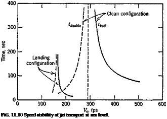
With this data, the values of CL and Ve at (L/D)max are, respectively, C’L = .595 and V — 290 fps. The result of the calculation with (11.5,5) is shown in Fig. 11.10. There is positive “speed stability” above 290 fps, but the characteristic time to half is large, in excess of 75 sec. In the low – speed range (sometimes referred to as “the backside of the polar,” with reference to the CL — CD “polar” diagram), the motion is unstable, with time to double falling as low as 30.5 sec at 0L = 1.6. A low-speed landing approach with this speed characteristic is undesirable from a handling – qualities standpoint (see Sec. 12.8). On the other hand, the example corre­sponds to cruising flight, not landing, since wheels and flaps are retracted.

The speed stability is in fact quite sensitive to the drag characteristics of the airplane. Thus, suppose that undercarriage and flaps have been lowered on the jet transport, with large increases in parasite and included drag reflected in the polar equation

1 20 2

0D = 0.20 + (11.5,6)

Irr

The results for this case, also shown on Fig. 11.10, are very different. The divergence time to double is now greater than 30 sec for all speeds above about 99 mph.

EXAMPLE—ALTITUDE AND GLIDE-PATH CONTROL

One of the most important problems in the control of flight path is that of following a prescribed line in space, as defined for example by a radio beacon. This is crucial in the landing situation under poor visibility when the airplane flies down the ILS glide slope. We shall discuss this case by considering first a simple approximate model that reveals the main features, and then examining a more realistic, and hence more complicated case.

FLIGHT AT EXACTLY CONSTANT HEIGHT—SPEED STABILITY

The first mathematical model we consider can be regarded as that corre­sponding to horizontal flight when a “perfect” autopilot controls the angle of attack in such a way as to keep the height error exactly zero. The result will show that the speed variation is stable at high speeds, but unstable at speeds below a critical value near the minimum drag speed. Neumark (11.2) recounts that this criterion was first discovered in 1910 by Painleve, and that it was at first accepted by aeronautical engineers and scientists, but later, on the basis of the theory of the phugoid which showed no such effect, was rejected as false. In fact, to the extent that a pilot can control height error by elevator control alone, i. e. to the extent that he approximates the ideal autopilot we have postulated, the instability at low speed will be experienced in manual flight. Since speed variation is the most noticeable feature of this phenomenon, it is commonly referred to as speed stability.

The analysis that follows is essentially that of Neumark, but adapted to the notation and methods of this book. The basic assumption that the flight path is exactly horizontal implies у = 0, or в = ctx (see Fig. 4.4.), whence Ад = Да. An exactly horizontal flight path also implies L = W. The pitching moment equation is specified to be identically satisfied by means of an appropriate but unspecified control device that supplies the needed pitching moment as required. The system equations are then (5.13,19) with Act. = A6, ye = 0 and the third equation missing. We further specify that a. T = 0. The equations are then

DV

=

і <6V – cv

0

_<V«

2fl

Av

Да

Л

4

Da.

Clv + 2CVe 2/г – f – Cl&

о La + CDf

2/* – 2/i + Ci&

0

Da

0

0

1

0

Да

(11.5,1

We now make some simplifying approximations, i. e. that the speed deriv­atives CDv and CLf are negligible and that 2ц > CL&, CL^. Actually these are very weak approximations for a conventional airplane in cruise con­figuration. On combining the Да terms of the first two equations, eliminating q by means of the third, and observing that CLe = CWg, we get

2fiDV = CTv AV – CD Да

v

0 = 2CL AV + Gjr Да (11.5,2)

e

Elimination of Да yields the first-order speed equation

2fiDV = (cTv + 2Cd G-^ At (11.5,3)

The speed variation following an initial speed error AF0 is clearly expo­nential,

AV = AV0e}>f

with time constant given by

Подпись: 4-VT,

EXAMPLE—ALTITUDE AND GLIDE-PATH CONTROL Подпись: (11.5,4)

2M OlJ

We must now specify a propulsion system in order that CTfr may be deter­mined. The result finally obtained depends on this choice, but only in the actual value of the critical speed, not its existence. We arbitrarily choose a constant-thrust engine, for which (see Table 7.1)

®ту — 2<^те — —D)S Equations (11.5,4) then yield

EXAMPLE—ALTITUDE AND GLIDE-PATH CONTROL(11.5,5)

EXAMPLE—ALTITUDE AND GLIDE-PATH CONTROL

The factor in the inner parentheses can be rewritten as

where dCLjdCD is the slope of the tangent to the drag polar, and CLjCD is the slope of the secant, see Fig. 10.2. Just as in Sec. 10.2, Eq. (10.2,17), this factor passes through zero at the point C’L, С’р where LjD is a maximum. It is positive for CL > C’L and negative for CL < C’L. If V be the speed
corresponding to (L/D)max, then the speed variation is seen to be stable for V > V, but unstable for V < V. That is, speed errors will die out at high speeds, but grow at low speeds. This phenomenon is seen to be related to the change of sign of KyS that occurs at the same critical speed (Sec. 10.2).

ELIMINATION OF STEADY-STATE RUDDER ANGLE

The solution presented above contains a feature which could possibly he undesirable—i. e. there is a steady-state rudder angle associated with constant yaw rate r. This means that the autopilot would generate a rudder deflection during steady turns, with 8r > 0 for right turns and vice versa. This is opposite to the rudder deflection wanted in the turn (see Sec. 10.4), and hence we have the autopilot opposing the human pilot. If this situation occurred with any frequency, the pilot rating of the aircraft would be ad­versely affected. On the other hand, CWe = 4.0 represents a very low speed, presumably associated only with landing and take-off, and not ordinarily with turning flight. Thus it would depend on factors somewhat outside the scope of this example whether this steady-state behavior of the autopilot presented a problem or not.

In cruising flight this problem would be more serious, and it would be desired to eliminate it. We illustrate here how it could be done.

The steady-state response of the rudder system can be eliminated by incorporating what amounts to a high-pass filter with zero static gainf in the rudder loop, as shown in Fig. 11.8. The feedback element if23r-s/(l + ts) f A “washout” circuit.

Fig. 11.8 Stability augmentation system for STOL airplane.

has zero static gain (see Sec. 3.2), so that 6r is zero when r = const. The frequency response of this element is

ELIMINATION OF STEADY-STATE RUDDER ANGLE(11.4,8)

so that for сот —> oo, G(im) —»■ K23. Thus by proper choice of r, the filter can be made to behave like a simple gain of K23 above a chosen frequency cov To analyze the system with the filter incorporated, we could find the overall transfer function of the closed-loop system and calculate the roots of the characteristic equation, or alternatively we can modify (11.4,7) to correspond to Fig. 11.8. The latter procedure is by far the simpler in the present instance. The only respect in which (11.4,7) does not apply is in the last of the equations, which now must correspond to

ELIMINATION OF STEADY-STATE RUDDER ANGLE(11.4,9)

Подпись: or[12 + (1 + 12t).s + r. s2] ДST = K2Srsf

The corresponding differential equation is

Подпись: (11.4,10)

ELIMINATION OF STEADY-STATE RUDDER ANGLE Подпись: Ku
ELIMINATION OF STEADY-STATE RUDDER ANGLE
Подпись: Pilot inputs
Подпись: s+ 10
Подпись: Aircraft
Подпись: r

12 Д<5Г + (1 + 12т) 6r + т8г = K23rf

ELIMINATION OF STEADY-STATE RUDDER ANGLE

After conversion to nondimensional form, this becomes

Подпись: Ddr = t

On defining a new variable £, we can replace this second-order equation by a pair of first-order ones, i. e.

The last of (11.4,7) has now to be replaced by the pair (11.4,12). In doing so we eliminate Dr from (11.4,12) by using the third equation of (11.4,7). The result is shown as (11.4,13).

Computations made with (11.4,13) show that the effect of the autopilot in correcting the spiral instability is very much reduced by the filter unless r is very large (Pig. 11.9), in which case the effectiveness of the washout circuit is impaired. As has been pointed out previously, however, a slow divergence of the spiral mode is not unacceptable, so a compromise solution is possible without excessive values of r. Por example, with К1г = 15, К23 = 20 and г = 10 sec the modal characteristics are

Подпись: Iml

Spiral: fdouble = 18.1 sec Oscillation: T — 11.4 sec, NX/i = .56 cycles

ELIMINATION OF STEADY-STATE RUDDER ANGLE

0.020

Pig. 11.9 Effect of washout circuit on lateral roots. Ku = 15, K23 — 20.

EXAMPLE—STABILITY AUGMENTATION SYSTEM FOR STOL AIRPLANE

In Sec. 9.8, where we considered an example STOL airplane, we found that the spiral mode was unstable, with an uncomfortably short time to double. We remarked there that a feedback stability augmentation system might be useful. How should we proceed to synthethize such a system? We can choose any of (/3, p, r) as variables to sense, and feedback functions of them [cf. (11.2,1)] to produce command signals for the aileron and/or rudder. But which variables shall we choose and what functions of them shall we use? Here the “flight dynamicist’s approach” of looking at the feedback control system as a way of modifying the aerodynamic derivatives (Sec. 11.1) is helpful. The full set of synthetic changes that can be made in the six lateral moment derivatives is described by the relations

(11.4Д)

Подпись: (11.4,2)

where [&y] is the 2×3 matrix of feedback gains, i.e.

Подпись: and Подпись: (11.4,3)

Thus for example,

Equations (11.4,2) are written in dimensional rather than nondimensional form, since the sensing devices used to generate the feedback signals would ordinarily operate on the dimensional physical variables.

These relations must now be applied with good engineering judgment. Stumbling about blindly in the six-dimensional parameter space of the к. и is not a satisfactory way to find the solution. First, the number of nonzero k{j must be kept to a minimum, since each one entails extra hardware or circuitry, adding to weight, cost, complexity, and failure probability. Second, the engi­neer must take advantage of his understanding of the system and of the
fault to be corrected. Here the fault is that the spiral mode is unstable, the other two modes being stable. We know that the criterion for spiral stability in horizontal flight is (9.7,6)

«Ух “ > 0 (H.4,4)

and that it must be the violation of this criterion that is the cause of the instability. On examining Table 9.9—for example at Cw = 4.0—we find the left hand side of (11.4,3) to be

(,010)(—.25) – (,67)(.120) < 0

We also observe that there is no hope of correcting the situation without changing the sign of one of the four derivatives. In fact the one to which our attention is naturally directed is Ct, which is here positive, but is ordi­narily negative for “well-behaved” airplanes. A “synthetic” Glfi of the required sign can be introduced by aileron feedback of the form

= ^11^> ^11 > 0

In fact, an attempt at a solution based on this sideslip feedback for Gw = 4.0 was unsuccessful. When ku was made large enough to stabilize the spiral mode, the lateral oscillation was driven unstable. Now we observe from

(9.7,13) that Cn is the main factor available to control the damping of the lateral oscillation and hence an increase in |(7n | is indicated. This is also beneficial in meeting (11.4,4) when combined with a change of sign of Glfi. We therefore choose a second nonzero gain, k23, so that the control de­flections are given by

Д<5Г = k23r k23 > 0 (11.4,5)

The control derivatives assumed for this example, representative of those that pertain to a deflected sHpstream configuration, are

@ida = —-13/rad = -.30/rad

GnSa = +.04/rad C4r = +.04/rad

With these derivatives, and a control law given by (11.4,5), values of к1г and k23 can readily be found that eliminate the instability in the spiral mode while maintaining a stable lateral oscillation. In point of fact it is only a little more difficult in this case to incorporate a more realistic feedback law than the simple gains of (11.4,5). Consequently the example has not been computed with (11.4,5) but rather by assuming that each control actuator is a first-order dynamic system of fast response time. The corresponding control equations used were

which implies that the time constants of the aileron and rudder position servos are, respectively, xo and – A – sec> that there are zero time lags in the fj and r sensors, and that the steady-state gains are

Aileron: = Аи/10 deg/deg

Rudder: Jczs = K23/12 deg/(deg/sec)

Equations (11.4,6) are now incorporated into the basic lateral equations of motion to yield the final mathematical system. After converting (11.4,6) to nondimensional form, we get the result (11.4,7). The eigenvalues of (11.4,7)

Dp

CVft

Cyr 1

Cwe

0

0

P

2p

2(1

2ц A

2(1

Dp

Civ

Clr

Cha

chr

A

І’х

К

V

Jx

0

r.

rx

V

Dr

Gn0

Gnv

Cn0

0

Сща

C«Sr

л

=

n

V

xz

V

J-Z

n

Ц

D<j>

0

1

A

0

0

0

0

Ф

DSa

Kllt*

0

0

0

— Ш*

0

Дй«

Ddr

0

0

-^■23

A

0

0

— 12г*

ASr

(11.4,7)

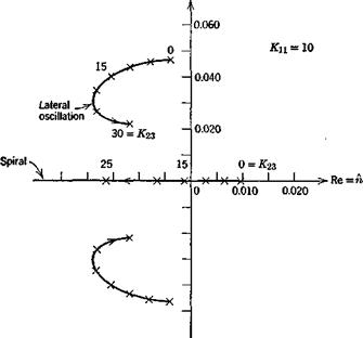
were calculated for ranges of Kn and K23, and a typical root locus is shown on Fig. 11.7. There is a substantial range of practical gains for which stability is achieved. For example for KX1 = 10, K23 = 20, the spiral and Dutch-roll characteristics are

Spiral: fj^ = 7.4sec

Oscillation: T = 12.4 sec, = .21 cycles

The corresponding control gains are, respectively, 1 deg/deg for the aileron, and 1.67 deg/(deg/sec) for the rudder. These are both quite modest, and would not likely present any exceptional problems of control design.

Im =a>

EXAMPLE—STABILITY AUGMENTATION SYSTEM FOR STOL AIRPLANE

Fig; 11.7 Root loci for stability augmentation system.

COUPLING OF CONTROLS WITH ELASTIC DEGREES OF FREEDOM

In Sec. 5.12 we presented equations of motion for elastic modes with con­trols locked in a fixed position, and in the preceding section we have developed the control equations for a rigid airplane. Thus, coupling between controls and elastic motions has been excluded. In fact, as is clear from the existence of the aileron reversal phenomenon (Sec. 8.4), and the effect of flexibility on elevator effectiveness (Sec. 7.4), there are important couplings between the control degrees of freedom and the elastic degrees of freedom. To include these entails modifications to both the elastic equations (5.12,7) and (5.12,12) and control system equations such as (11.3,12). The details depend on

which control system is being considered—aileron, elevator, or rudder—and on its particular design features. We illustrate the process by considering the elevator surface and its coupling with z deflections of the vehicle. We treat a case of one degree of freedom by stipulating dj = 0.

The deflection of the structure from the reference position is now given by [cf. (5.12,1)]

z'(t) =^hn(xo, y0, z„)en(t) + hsMe(t)

n—0

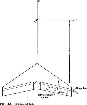
where hd is zero except for points of the elevator, where it is hs — | and f is the distance from the elevator hinge line, as shown on Fig. 11.5. Now the displacement function represented by the last term is not in general ortho­gonal to the hn, and hence the integrals of its products with them that appear in the kinetic energy do not vanish. This leads to the appearance of an additional term on the l. h.s. of (5.12,7), viz. (an exercise for the reader)

1п(ёп + 2£иа>„ёи + mr^e) + Ins $e — ^n (11.3,23)

where InS=jhn!-dm

the integral being taken over the elevator.

Similarly, the l. h.s. of (11.3,13a) (with 6j — 0) becomes

co

= (11-3,24)

n= 0

The terms containing lni in these equations represent inertial couplings be­tween the elevator and elastic degrees of freedom. That in (11.3,23) corre­sponds to “tail wags dog,” i. e. acceleration de of the elevator generates motion in the wth elastic mode. This may be expected to be a small effect in most cases. That in (11.3,24) represents the converse, “dog wags tail,”

i. e. elastic mode accelerations en generate motion of the elevator. This contribution is very significant in relation to control-surface flutter, and is minimized by proper mass balancing of the control surface to reduce Ini for the critical elastic mode.

The remaining modifications to the equations of motion occur on the r. h.s. For the elastic modes the only addition is one aerodynamic term to #”и, i. e. AnS A. de to (5.12,12) or GnS Ade to (5.12,13). These aerodynamic contributions to elastic motion are usually important. The addition to the control equation is also an aerodynamic coupling. There He in (11.3,13c) becomes

00

He= –+ ZHnsen

n=0

In summary, the elastic and control equations are both modified by addi­tional simple inertial terms on the l. h.s and by aerodynamic terms on the r. h.s.

THE SERVO EQUATION

The pair of equations (11.3,13) do not normally give the whole picture. The control system illustrated in 11.4 is intended to operate with 6j as near to zero as possible. Typically a hydraulic system for this application would sense 6j as an error, and control the flow of high-pressure fluid to the piston so as to reduce it. A solenoid-controlled servo that could perform this function is illustrated in Fig. 11.6. The ports are such that the actuator is forced to follow the valve spool. In this case the error signal might be generated by a displacement transducer attached to the link A В of Fig 11.4 and used via an intervening electronic system to position the value spool. Alternatively, an entirely mechanical linkage could connect the valve spool to the pilot’s control. Servos like this one have the characteristic that the volume rate of flow of oil is very nearly proportional to the valve error, regardless of load.

High-pressure

Oil return supply Oil return

THE SERVO EQUATION

Fig. 11.6 Schematic of solenoid-controlled hydraulic servo.


Since the flow rate is proportional to the velocity of point A, which is a linear combination of Se and 6j, and since the valve error is proportional to 0 j, the servo equation in this case would be

ade + 6j = bOj (11.3,16)

Подпись: -kПодпись: 22Подпись: P (11.3,17)Подпись:Adding this equation to (11.3,13) completes the system, and has the effect of transferring J to the autonomous set of state variables, leaving only P as a nonautonomous input. The functioning of the servo itself in the neighbor­hood of an equilibrium point, as an uncoupled system, is described by putting Д F, a, and q = 0, leading to the control system equations (in Laplace trans­forms)

Подпись: eJ* ijs2

as

From this equation the ДSJP transfer function can readily be found. The characteristic equation is found by expanding the determinant of the 3×3 matrix, and is a cubic.

If the servo is powerful enough that в j may be assumed to be identically zero, then a substantial simplification results. In that case (11.3,16) is super­fluous and J can be eliminated via (11.3,12), i. e.

j = {I eJ be-hxP) (11.3,18)

&22

If furthermore the inertial coupling IeJ is negligibly small, which can be ensured by design, we get the desirable simple result

J = — —P = kP (11.3,19)

^ 22

Assuming both the above conditions to hold, the first system equation reduces

and gives a second-order transfer function connecting P and Д<5е. The corre­sponding equation with the a and q terms present is obtained from (11.3,13a) as

-HrAv + [(meeeFe – Hp. s – #J Да – {Pexs + meeeVe + Ha)q

+ (V – Hyt- Hs) Ade = KP (11.3,21)

THE SERVO EQUATIONwhere

Although perfect dynamic balance of the elevator surface may not always be achieved, the inertia coupling terms are often small. If they can be neglected, we get the simplest equation that still contains the essential ingredients of the control dynamics—i. e. the inertia of the control elements and the aerodynamic feedbacks:

-Hr AY – (HAs + Ha) Да – Hgq + (IjP – Hhs – Ht) ASe = KP (a)

(11.3,22)

Подпись: (11.3,22)
THE SERVO EQUATION

With similar assumptions, the equations for the other two control systems are Rudder system:

For the aileron system, dx is the downward deflection of the right-hand surface, assumed equal to the upward deflection of the left-hand surface. Ia is the generalized inertia of the entire system comprising both surfaces and all connected parts, but H is the aerodynamic hinge moment on one surface only.

INERTIAL COUPLING

Although little can be done to influence the aerodynamic coupling, the inertial coupling is amenable to control by design. If the elevator mass center is on the hinge line, ee = 0 and one coupling term vanishes—i. e. acceleration in the z direction will then not tend to induce motion of the control. With reference to Fig. 11.5, we can calculate Pex as follows

INERTIAL COUPLING(11.3,14)

For Pex and ee both to be zero, we would require

INERTIAL COUPLING(11.3,15)

This condition cannot be met if Л = 0, but in principle can be if Л Ф 0 by the addition of suitable balance weights. When both Pex and ee are zero we have complete dynamic balance of the elevator, and rigid body motion of the vehicle does not induce motion of the control.

The problem of reducing inertia coupling when aeroelastic flutter is the issue is similar to, but not the same as, that discussed here. The relevant product of inertia would in general be a different one [see (11.3,24)].

EQUATIONS OF MOTION

The equations of motion are obtained by substituting the generalized forces and the kinetic energy in Lagranges equations, i. e

Je К + IeJ®J = 11 e + fellp + ki2J — «W*02 – PexiPr — І) («)

I’jk + IjSj = k2lP + k2*J (b)

(11.3.12)

The inertia terms on the r. h.s. of (a) are the only nonlinear ones, and in view of the assumptions already made, linearization of these is in order. a0 is the a component of the acceleration of the vehicle mass center and is given by (5.3,18). Without the Earth rotation terms, and for small distur­bances, we get

a0 — w — qu

From (4.3,4), in the linear case, w = Vv. x and и = V, so that the linear expression for the acceleration is

<4 = У A – я К

and (11.3,12) become

Je 4 + Ie. jbj = 11 e + Kip + lciiJ — meeeVe(± — q} + Pexq (a)

U + ^A = V + V (Ь)

(11.3.13)

These equations, when combined with the vehicle equations of motion, convert 8e from a nonautonomous to an autonomous variable, add Qj to the autonomous set, and introduce P and J as nonautonomous variables. The aerodynamic force He is a function of the state variables, i. e. [cf. (6.5,2)]

He = He0 + Hv AF + Ha Да + Я*« + HQq + H, Аде + Щ Se (c)

(11.3.13)

and provides aerodynamic coupling (feedback) between the vehicle motion and the control force. Similarly the terms containing a and q in (11.3,13a) provide inertial coupling between vehicle and control dynamics.

THE KINETIC ENERGY T

The kinetic energy of the moving masses (elevator, levers, pistons, rods, etc.) can for small displacements always be expressed in the form

т = ¥ейе2 + ^КЬ + ¥Л2 (H-3,1)

The coefficients of this equation are generalized inertias, and could be com­puted by integrating the energy associated with de and Oj over all the moving material system. These inertias are assumed to be constants.

THE GENERALIZED FORCE &n

The generalized force is given by (5.12,8), where W is the work done by the external aerodynamic and inertia forces during a virtual displacement of the system. Let it be expressed as

AW = He A<5e + P AsP + J ksj + ATT, (11.3,2)

where sP and Sj are the displacements of the forces P and J respectively,

THE KINETIC ENERGY T Подпись: dW, dde Подпись: (a) (b) Подпись: (11.3,3)

and Wt is the work done by the inertia forces. Thus

The kinematic derivatives dsPjdbe, etc., are simple constants, readily deter­mined from the geometry of the linkage.

We now require the derivatives of W{. The inertia force field is given by

= —(a — Ї’) dm (11.3,4)

where a is acceleration of dm relative to Fj given by (5.1,8) and r’ = [x, y, zT is its position vector in FB. The work done in a virtual displacement by this field is

A Wi =J (dfx. Аж + dfy. Д у + dfz. A z) (11.3,5)

where the integration is taken over the whole control system. To carry out this integration exactly clearly requires complete information about the masses, sizes, and locations of all the moving elements. It is in principle a straightforward albeit tedious process. In the interests of simplicity we neglect all contributions to W{ except those of the elevator surface itself, and that we treat as a lamina lying in the xy plane. The relevant geometry is shown in Fig. 11.5. The displacement of the element dm is in the direction Cz and of magnitude f ASe. Hence only the last term of (11.3,5) is nonzero, so that

А1Г, =jdf::£Ade

THE KINETIC ENERGY T

On using (11.3,4) and (5.1,8), remembering that z — x = у = 0, we get

vanishes. The first is, by virtue of the definition of mass center,

jgdm = meee (11.3,8)

where me is the mass of both elevators, and ee is as shown in Fig. 11.5. The second integral is the product of inertia of the elevator w. r.t. its hinge line and the у axis. It is denoted

jx£dm = Pex (11.3,9)

Equations (11.3,7) now read

Подпись: dW; dde

THE KINETIC ENERGY T

dWt

dOj

and finally, on combining (11.3,10) and (11.3,3) we get the generalized forces = — = He + hip + ki2J – Wo, – Pex(Pr – Я.) (11-3,11)

0Oe

dW

^» = ГТ———– 1" k21P + k22^

dVj

where [ky] is the matrix of kinematical gearings dsPjdde, etc.