Category Dynamics of Flight

NOTATION FOR SMALL DISTURBANCES

The reference values of all the variables are denoted by a subscript zero, and the small perturbations by prefix Д. When the reference value is zero, the Д is omitted. All the disturbance quantities and their derivatives are assumed to be small, so that their squares and products are negligible compared to first-order quantities.

The reference flight condition is assumed for convenience to be symmetric and with no angular velocity. Thus v0 = p0 = q0 = r0 = ф0 = 0. Furthermore, stability axes are selected as standard in this book, and thus w0 = 0 for all the problems con­sidered. u0 is then equal to the reference flight speed, and в0 to the reference angle of climb (not assumed to be small). In dealing with the trigonometric functions in the equations the following relations are used:

sin (0O + Ав) = sin в0 cos Ав + cos в0 sin Ав = sin в0 + A0cos 60

cos (в0 + Ав) = cos 60 cos Ав – sin в0 sin Ав (4.9,1)

= cos в0 — Ав sin 6>0

The Small-Disturbance Theory

As remarked in Sec. 4.8, the equations of motion are frequently linearized for use in stability and control analysis. It is assumed that the motion of the airplane consists of small deviations from a reference condition of steady flight. The use of the small-dis­turbance theory has been found in practice to give good results. It predicts with satis­factory precision the stability of unaccelerated flight, and it can be used, with suffi­cient accuracy for engineering purposes, for response calculations where the disturbances are not infinitesimal. There are, of course, limitations to the theory. It is not suitable for solutions of problems in which large disturbance angles occur, for ex­ample Ф = 77-/2.

The reasons for the success of the method are twofold: (1) In many cases, the major aerodynamic effects are nearly linear functions of the disturbances, and (2) dis­turbed flight of considerable violence can occur with quite small values of the linear – and angular-velocity disturbances.

RESPONSE TO ATMOSPHERIC TURBULENCE

The motion of an airplane, and the forces that act on it, as a consequence of the tur­bulent motion of the atmosphere, are very important for both design and operation. The associated mathematical problems are treated with the same general equations as given above. (uE, vE, we) then have to be sums of (u, v, w) and the velocity of the at­mosphere at the CG, and additional complications arise from the fact that the relative wind varies, in general, from point to point on the airplane. This case is treated in depth in Chap. 13 of Etkin (1972) and in Etkin (1981).

INVERSE PROBLEMS

A class of problems that has not received much attention in the past, but that is never­theless both interesting and useful, is that in which some of the 12 variables usually regarded as dependent are prescribed in advance as functions of time. An equal num­ber of equations must then be dropped in order to maintain a complete system. This is the kind of problem that occurs when we ask questions of the type “Given the air­plane motion, what pilot action is required to produce it?” Such questions may be rel­evant to problems of control design and maneuvering loads.

The mathematical problem that results is generally simpler than those of stability and control. The equations to be solved are sometimes algebraic, sometimes differen­tial. A decided advantage is the ability of this approach to cope with the nonlinear equations of large disturbances.

Another category is the mathematical problem that arises in flight testing when time records are available of some control variables and some of the 12 dependent variables. The question then is “What must the airplane parameters be to produce the measured response from the measured input?” (See Etkin, 1959, Chap. 11; AGARD 1991; Maine and Iliff, 1986.) This is an example of the important “plant identifica­tion” problem of system theory.

STABILITY PROBLEMS—AUTOMATIC CONTROLS

When the airplane is under the control of an AFCS the controls are neither fixed nor free. The control vector c, which fixes the control inputs of Fig. 4.4, are then deter­mined by the feedback loop that activates the control systems in response to the val­ues of the 12 dependent variables and inputs from other sources such as navigation, guidance, or fire control systems, and so on. Problems of this class are studied in Chap. 8.

RESPONSE TO CONTROLS

The effectiveness of an airplane’s controls is conventionally studied by specifying the variation of (Se, Sr, 8a, 8p) with time arbitrarily, e. g., a step-function input of aileron angle. The airplane equations of motion then become inhomogeneous equations for (u, v, w), (p, q, r), (в, ф, ф) with the control angles as forcing functions. Problems of this type are treated in Chap. 7.

STABILITY PROBLEMS—CONTROLS FIXED

In these problems the airplane is considered to be disturbed from an initially steady flight condition, with the controls locked in position. Thus, c is zero or a known con­stant. The equations are nonlinear and, consequently, extremely difficult to deal with analytically. In many problems of practical importance, it is satisfactory to linearize the equations by dealing only with small perturbations from the reference condition. In that case we obtain a set of homogeneous linear differential equations with con­stant coefficients, a type that is readily solved. Problems of this class are treated in Chap. 6.

STABILITY PROBLEMS—CONTROLS FREE

The free-control case is of interest primarily only for manually controlled airplanes. In that case, one or more of the primary control systems is presumed to be freed as in “hands off” by the pilot. The variation of the control angles with time, which is of course needed for the aerodynamic force and moment inputs, is then the result of an interaction between the dynamics and aerodynamics of the vehicle and those of the control system itself, which is usually simplified as a system with one degree of free­dom relative to FB. For a derivation of these equations see Etkin (1972, Sec. 11.3). Each such free control adds one dependent variable and one equation to the mathe­matical system.

Discussion of the Equations

The above equations are quite general and contain few assumptions. These are:

1. The airplane is a rigid body, which may have attached to it any number of rigid spinning rotors.

2. Cxz is a plane of mirror symmetry.

3. The axes of any spinning rotors are fixed in direction relative to the body axes, and the rotors have constant angular speed relative to the body axes.

The equations of Sec. 4.7 are many and complex. They consist of 15 coupled nonlinear ordinary differential equations in the independent variable t, and three alge­braic equations. Before we can identify the true dependent variables, however, we must first consider the aerodynamic forces (X, Y,Z) and moments (L, M,N). It is clear that these must depend in some manner on the relative motion of the airplane with re­spect to the air, given by the linear and angular velocities V and to, on the control variables that fix the angles of any moveable surfaces and on the settings of any propulsion controls that determine the thrust vector. Thus it is universally assumed in flight dynamics that the six forces and moments are functions of the six linear and angular velocities (u, v,w, p,q, r) and of a control vector. The latter clearly depends to

some extent on the particular airplane, but we can, with adequate generality, write it

as

c = [Su gr 8PY

of which the first three are the familiar aileron, elevator, and rudder angles, and the last is the throttle control. Other components can be added to the control vector as needed to meet special requirements—for example, direct lift control. The control variables, from the standpoint of the mathematical system, are arbitrary functions of time. How they are determined is the subject of later sections. The wind vector whose components appear in (4.7,5) would ordinarily be a known function of position rc with its components given in frame FE. Its components in FB are W/; = LS£W£.

The true implicit dependent variables of the system are thus seen to be 12 in number:

CG position: xE, yE, zE Attitude: ф, в, ф Velocity: uE, vE, we Angular velocity: p, q, r

Of the 15 differential equations we note that 3 of (4.7,3) are not independent, so the number of independent equations is actually 12, the same as the number of de­pendent variables. The mathematical system is therefore complete.

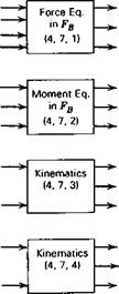
A useful view of the equations is given in the block diagram of Fig. 4.4, which is specialized to the case of zero wind. Each block represents one set of equations, with inputs and outputs (the dependent variables). All the inputs needed for the left-hand side are generated as outputs on the right, except for the control inputs, which remain to be specified. The nature of the mathematical problem that ensues is very much

Подпись: в, ф u,v,w Подпись:Подпись: u,v,wПодпись: p.g.r Control moments Подпись: P>4,rПодпись: U, V, wПодпись: ф,в,фПодпись: V w Подпись:Discussion of the EquationsПодпись: в,ф{]>—– “

fl>—– o

ф——- »

-Q>—- p

—— «

Q>——–

■D>— Ф

■Q>—- 8

{D—*

{D— XE

-П>—- Уе

-Q>– ZE

Figure 4.4 Block diagram of equations for vehicle with plane of symmetry. Body axes. Flat-Earth approximation. No wind.

governed by the specifics of the control inputs. In the following paragraphs, we dis­cuss the various cases that commonly occur in engineering practise and in research.

The Equations Collected

The kinematical and dynamical equations derived in the foregoing are collected be­low for convenience. The assumption that Cxz is a plane of symmetry is used, so that Ixv = Iyz = 0, and (4.6,2) are added to (4.5,9) to give (4.7,2).

’Note that the inertias of the rotors are also included in Is.

X — mg sin в = т(йЕ + qwE — rvE)

(a)

Y + mg cos в sin ф = m(vE + ruE — pwE)

(b)

(4.7,1)

Z + mg cos в cos ф = m(wE + pvE — quE)

(c)

L = IJ> – Izxr + qr(L – Iy) – Lxpq + qh’z – rh’y

(a)

M = Iyq + rp(Ix – Iz) + IJp2 – r2) + rh’x – ph’z

(b)

(4.7,2)

N = Izr- Izxp + pq(Iy – lx) + Izxqr + ph’y – qh’x

(c)

p = ф — ф sin в

(a)

q = в cos ф + ф cos в sin ф

(b)

r = ф cos в cos ф — 0 sin ф

(c)

ф = p + (q sin ф + r cos ф) tan в

(d)

(4.7,3)

в = q cos ф — r sin ф

(e)

ф = (</ sin ф + r cos ф) sec в

(f)

xE = uE cos в cos ф + u£(sin ф sin в cos ф — cos ф sin Ф) + w£(cos ф sin в cos ф + sin ф sin Ф)

(a)

yE = uE cos в sin ф + u£(sin ф sin в sin ф + COS Ф COS Ф)

(4.7,4)

+ w£(cos ф sin в sin ф — sin Ф COS Ф)

(b)

ZE = —UE sin в + vE sin ф cos в + wE COS Ф cos в

(c)

uE = u + Wx

(a)

Vе = V + Wy

(b)

•(4.7,5)

wE = w + Wz

(c)

Effect of Spinning Rotors on the Euler Equations

In evaluating the angular momentum h (see Sec. 4.3) it was tacitly assumed that the airplane is a single rigid body. This is implied in the equation for the velocity of an element (4.3,2). Let us now imagine that some portions of the airplane mass are spin­ning relative to the body axes; for example, rotors of jet engines, or propellers. Each such rotor has an angular momentum relative to the body axes. This can be computed from (4.3,4) by interpreting the moments and products of inertia therein as those of the rotor with respect to axes parallel to Cxyz and origin at the rotor mass center. The angular velocities in (4.3,4) are interpreted as those of the rotor relative to the air­plane body axes. Let the resultant relative angular momentum of all rotors be h’, with components (h’x, h[„ /г’) in FB, which are assumed to be constant. It can be shown that the total angular momentum of an airplane with spinning rotors is obtained simply by adding h’ to the h previously obtained in Sec. 4.3 (see Exercise 4.5). The equation that corresponds to (4.3,4) is then6

hB = I BwB + hj, (4.6,1)

Because of the additional terms in the angular momentum, certain extra terms appear in the right-hand side of the moment equations, (4.5,9). Those additional terms, known as the gyroscopic couples, are

In the L equation: qh’z — rh’y

In the M equation: rh’x — ph’z (4.6,2)

In the N equation: ph’y — qh’x

As an example, suppose the rotor axes are parallel to Cx, with angular momentum h’ = i/fl. Then the gyroscopic terms in the three equations are, respectively, 0, /fir, and —IClq.

CHOICE OF BODY AXES

The equations derived in the preceding sections are valid for any orthogonal axes fixed in the airplane, with origin at the CG, and known as body axes. Since most air­craft are very nearly symmetrical, it is usual to assume exact symmetry, and to let Cxz be the plane of symmetry. Then Cx points “forward,” Cz. “downward,” and Су to

Horizonta

Подпись: Zp Principal axes Подпись:Подпись:CHOICE OF BODY AXESthe right. In this case, the two products of inertia, Ixy and lyz, are zero, and (4.5,9) are consequently simplified.

The directions of Cx and Cz in the plane of symmetry are conventionally fixed in one of three ways (see Fig. 4.3).

Principal Axes

These are chosen to coincide with the principal axes of the vehicle, so that the re­maining product of inertia I7X vanishes; (4.3,4 and 5) then yield

CHOICE OF BODY AXES(4.5,10)

Stability Axes

These are chosen so that Cx is aligned with V in a reference condition of steady symmetric flight. In this case, the reference values of v and w are zero, and the axes are termed stability axes. These axes are commonly used, owing to the simplifica­tions that result in the equations of motion, and in the expressions for the aerody­namic forces.

With this choice, it should be noted that for different initial flight conditions the axes are differently oriented in the airplane, and hence the values of Ix, /,, and l7X will vary from problem to problem. The “stability axes,” just as the principal axes, are body axes that remain fixed to the airplane during the motion considered in any one problem.

The following formulas are convenient for computing Ix, Iz, I7X when the values IXp and / are known for principal axes (see Exercise 4.4).

Подпись: (4.5,11)Ix = I cos2 € + IZp sin2 € L = Ir sin2 e + L cos2 є

z Xp Zp

Подпись: 1

4* = 2 (4> – 4„) sin 2e

where є = angle between xp (principal axis) and xs (stability axis), positive as shown (see Fig. 4.3).

Body Axes

When the axes are neither principal axes nor stability axes, they are usually called simply body axes. In this case the x axis is usually fixed to a longitudinal refer­ence line in the airplane. These axes may be the most convenient ones to use if the aerodynamic data have been measured by a wind-tunnel balance that resolves the forces and moments into body-fixed axes rather than tunnel-fixed axes.

ORIENTATION OF THE AIRPLANE

We now need a set of differential equations from which the Euler angles can be cal­culated. These are obtained as follows: Let (i, j, k) be unit vectors, with subscripts 1, 2, 3 denoting directions (jc,, jq, z,), and so on of Fig. 4.2.

Let the airplane experience, in time At, an infinitesimal rotation from the position defined by ‘P, 0, Ф to that corresponding to (Ф + ДФ), (0 + Д0), (Ф + ДФ). The vector representing this rotation is approximately

Дп = i3 ДФ + j2 Д0 + ki ДФ

ORIENTATION OF THE AIRPLANE

and the angular velocity is exactly

We begin with the force equation of (4.2,15):

fE = mVf (4.5,1)

Both vectors in (4.5,1) are now expressed in FB components; thus:

UJ„ = m 4 (LBBVf) = m{tEBWEB + Y,:J’n) (4.5,2)

at

The derivative of the transformation matrix is obtained from (A.4) as

= L eb&b (4-5,3)

With (4.5,3), (4.5,2) becomes

LBBfB = mil, EgtO/jV B + LEBVB)

Now premultiply by LB/: to get

fB = m(Vf + шв%) (4.5,4)

A similar procedure applied to the moment equation of (4.2,15) leads to

GB hB + <wBhB (4.5,5)

The force vector f is the sum of the aerodynamic force A and the gravitational force mg, that is,

f = mg + A (4.5,6)

where

AB = [X Y Z]T

and

mgB = mhBEgE = mLB/. |0 0 gf (4.5,7)

We denote VB = [u’ vE vva 17 and use (4.3,26) for wB. Equations (4.5,4 and 5) are then expanded using (4.3,4) to yield the desired equations. In doing so we note that

=

[L M

N]7 and

l that, because the airplane is

assumed to be rigid, Ів

= 0.

X — mg sin в = ,

m{tiE +

qwE —

rvE)

(a)

Y + mg cos в sin ф

= m(vE

+ ruE

-pwE)

(b)

(4.5,8)

Z + mg cos в cos ф

= m(wl

‘ + pvE

– quE)

(c)

L

= ~

“ Л АГ

~ r2) ~ IJr + pq) –

– ш ■

– rp) –

(Л – h)dr

(a)

M

= I yd ~

– I Jr

– P2) – hy(P + dr)

– f;Jr –

– Pd) –

(Л – Qrp

(b)

(4.5,9)

N

= hf~

– IJP2

– d2) – IJd + rp) ■

~ hIP

– qr) –

(Л – Iy)Pd

(c)