Category Dynamics of Flight

THE FLIGHT PATH

To track the flight path relative to FE, we need the velocity components in the direc­tions of the axes of Fe. These we get by transforming the velocity vector Уд into V); as shown in Appendix A.4.5

L/;z;V/І (4.4,1)

Here Leb is the matrix of direction cosines that corresponds to the reverse of the se­quence of rotations given above, which are for a transformation from FE to FB. Thus

Leb = Ьг(-ЧГ)Ц(-@)Ьх(-Ф) (4.4,2)

where Lv, Ly, Lz are respectively L„ L2, L3 of Appendix A.4. Using the rotation matrices given in Appendix A.4, and carrying out the multiplication, we get the final result (4.4,3).

Подпись:sin ф sin 9 cos ф — cos ф sin ф cos ф sin 9 cos ф + sin ф sin ф

sin ф sin 9 sin ф + cos ф cos ф cos ф sin 9 sin ф — sin ф cos ф

sin Ф cos 9 cos ф cos 9

(4.4,3)

Подпись: УЕ THE FLIGHT PATH

The differential equations for the coordinates of the flight path are then

-Ze-

The position of the vehicle CG is obtained by integrating the preceding equation.

“See. 5.2 of Etkin (1972).

“Appendix E of ANSI/AIAA (1992).

5Recall that the superscript signifies velocity relative to FE, and that the subscript identifies the ref­erence frame in which the components are given.

Orientation and Position of the Airplane

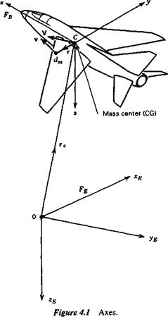
The position and orientation of the airplane are given relative to the Earth-fixed frame Fe. The CG has position vector rc (see Fig. 4.1), with coordinates (xE, yE, zE).

The orientation of the airplane is given by a series of three consecutive rotations, the Euler angles, whose order is important. The airplane is imagined first to be ori­ented so that its axes are parallel to those of FE, (see Fig. 4.2). It is then in the posi­tion Cx^^Zi – The following rotations are then applied.

1. A rotation Ф about oz i, carrying the axes to CX’2y2z2 (bringing Cx to its final azimuth).

2. A rotation ® about oy2, carrying the axes to Cx3y3z3 (bringing Cx to its final elevation).

3. A rotation Ф about ox3, carrying the axes to their final position Cxyz (giving the final angle of bank to the wings).

In order to avoid ambiguities which can otherwise result in the set of angles (ф, в, ф) the ranges are limited to

Orientation and Position of the Airplane

Figure 4.2 Airplane orientation.

~ТГ<ф<ТГ or 0^(/r<277

7Г 77

—— < 0< —

2 2

— 77<ф<77 ОГ 0 < <£ < 277

The Euler angles are then unique for most orientations of the vehicle. It should be noted that in a continuous steady rotation, such as rolling, the time variation of ф for example is a discontinuous sawtooth function, and that another exception occurs in a vertical climb or dive, when в = ±77/2. For then (ф, в, ф) = (ф + а, ±77/2, – а) gives the same final orientation regardless of the value of a. The above difficulties can be avoided by using direction cosines3 or quaternions4 to define the orientation of the airplane instead of Euler angles. We use the Euler angles because they give a more physical picture of the airplane attitude than the other alternatives. For a more complete discussion of methods of describing vehicle orientation the reader is re­ferred to Hughes (1986).

Evaluation of the Angular Momentum h

Evaluation of the Angular Momentum h

We shall want the angular momentum components in FB. Now

So in FB we have

Evaluation of the Angular Momentum h(4.3,1)

where

0 – z у r B= z 0 – x _-y x 0

Let the angular velocity of the airplane relative to inertial space1 be

<»B = [p 4 rf

where p, q, r are the rates of roll, pitch and yaw respectively (see Fig. 1.6).
Now the velocity of a point in a rigid rotating body is given by2

VB = Ve + taBrB (a)

Подпись: (4.3,2)

Подпись: so that Подпись: = Подпись: — r q 0 -p P 0 Подпись: (b)

where

hs = J fB(VB + coBrB)dm

= J rBB dm + J rBa>BrB dm

fe dmj VB + j rB(bBrB dm (4.3,3)

The first integral in (4.3,3) vanishes since the origin of г is the CG. When the triple matrix product of the second integral is expanded (see Exercise 4.2) we get the result

for hB:

hs ”

IBMB

(4.3,4)

where

" lx

^xy

-hz

Ifl =

^ XX

Is

-1,

(4.3,5)

L-/w

~hy

h J

and

Ix = j (y2 + z2)dm; Iy = J (x2 + z2)dm; Iz = j (x1 + y2)dm

(4.3,6)

hy = A t = {•*>’ dm Ixz = ]:x = f xz dm; Iyz = /:v = f yz dm

Ifi is the inertia matrix, its elements being the moments and products of inertia of the airplane. When the xz plane is a plane of symmetry, which is the usual assumption, then

^xy A 0

and the only off-diagonal term remaining is If the direction of the x axis is so cho­sen that this product of inertia also vanishes, which is always possible in principle, then the axes are principal axes.

‘Since there is no need to use the angular velocity relative to any other frame of reference the distin­guishing superscript E is not needed on at.

2See Appendix A.6.

The Rigid-Body Equations

In the interest of completeness, the rigid-body equations are derived from first princi­ples, that is to say, we apply Newton’s laws to an element dm of the airplane, and then integrate over all elements. The velocities and accelerations must of course be relative to an inertial, or Newtonian, frame of reference. As we noted in Sec. 1.6 the frame Fe, fixed to the Earth, is assumed to be such a frame. We also noted there that velocities relative to FE are identified by a superscript E. In order to avoid the carry­ing of the cumbersome superscript throughout the following development, we shall

temporarily assume that W = 0 in (1.6,1), so that Vе — V, and make an appropriate adjustment at the end. In the frame FB

VB = [u v w]r (4.2,1)

The position vector of dm relative to the origin of FE is rc + r (see Fig. 4.1). In the frame Fe,

r, f: = [xE Уе ZEf (4-2,2)

and in the frame FB

Подпись:Подпись: (4.2,4)Подпись: (4.2,5)rB = [x у z]T

The inertial velocity of dm is

v£ = (rCE + tE) = VE + rE

The momentum of dm is у dm, and of the whole airplane is

I Edm = I (V£ + rE)dm = E J dm + J tEdm
The Rigid-Body Equations

Since C is the mass center, the last integral in (4.2,5) is zero and

J xEdm = mV,, (4.2,6)

where m is the total mass of the airplane. Newton’s second law applied to dm is

dtE = Edm (4.2,7)

where d(E is the resultant of all forces acting on dm. The integral of (4.2,7) is

4 = j dfE = j *Edm

or, from (4.2,6)

f£ = mV£ (4.2,8)

The quantity /dfE is a summation of all the forces that act upon all the elements. The internal forces, that is, those exerted by one element upon another, all occur in equal and opposite pairs, by Newton’s third law, and hence contribute nothing to the summation. Thus fE is the resultant external force acting upon the airplane.

This equation relates the external force on the airplane to the motion of the CG. We need also the relation between the external moment and the rotation of the air­plane. It is obtained from a consideration of the moment of momentum. The moment of momentum of dm with respect to C is by definition rfh = rX xdm. It is convenient in the following to use the matrix form of the cross product (see Appendix A. 1) so that

dhE = fExEdm

Consider

d

— (dhE) = rEEdm + rEvEdm (4.2,9)

dt

Now from (4.2,4),

rE = yE~ VE

and the moment of dt about C is

dG = г X dt

so that from (4.2,7)

dGE = rEdfE = rEEdm (4.2,10)

Equation (4.2,9) then becomes

dGl: = — (dhE) – (x, – VE)yEdm (4.2,11)

Since v X v = 0, (4.2,11) becomes

d.

dG l: — — (dhE) + ExEdm dt

Equation (4.2,12) is now integrated as was (4.2,7), and becomes

The Rigid-Body Equations(4.2,13)

By an argument similar to that for $di, fdG is shown to be the resultant external moment about C, denoted G. fdh is called the moment of momentum, or angular mo­mentum of the airplane and is denoted h. Formulas for h are derived in Sec. 4.3. Us­ing (4.2,6) and noting that V X V = 0, (4.2,13) reduces to

(4.2,14)

The Rigid-Body Equations

where

The reader should note that, in (4.2,14), both G and h are referred to a moving point, the mass center. For a moving reference point other than the mass center, the equation does not in general apply. The reader should also note that (4.2,8) and

(4.2,14) are both valid when there is relative motion of parts of the airplane.

The Rigid-Body Equations

The two vector equations of motion of the airplane, equivalent to six scalar equa­tions, are (4.2,8) and (4.2,14)

When the wind vector W is not zero, the velocity E in (4.2,5) is that of the CG rela­tive to Fe. The angular momentum h is the same whether W is zero or not (see Exer­cise 4.1). Hence in the general case when wind is present the equations of motion are:

The Rigid-Body Equations(4.2,15)

General Equations of. Unsteady Motion

4.1 General Remarks

The basis for analysis, computation, or simulation of the unsteady motions of a flight vehicle is the mathematical model of the vehicle and its subsystems. An airplane in flight is a very complicated dynamic system. It consists of an aggregate of elastic bodies so connected that both rigid and elastic relative motions can occur. For exam­ple, the propeller or jet-engine rotor rotates, the control surfaces move about their hinges, and bending and twisting of the various aerodynamic surfaces occur. The ex­ternal forces that act on the airplane are also complicated functions of its shape and its motion. It seems clear that realistic analyses of engineering precision are not likely to be accomplished with a very simple mathematical model. The model that is developed in the following has been found by aeronautical engineers and researchers to be very useful in practise. We begin by first treating the vehicle as a single rigid body with six degrees of freedom. This body is free to move in the atmosphere under the actions of gravity and aerodynamic forces—it is primarily the nature and com­plexity of aerodynamic forces that distinguish flight vehicles from other dynamic systems. Next we add the gyroscopic effects of spinning rotors and then continue with a discussion of structural distortion (aeroelastic effects).

As was noted in Chap. 1, the Earth is treated as flat and stationary in inertial space. These assumptions simplify the model enormously, and are quite acceptable for dealing with most problems of airplane flight. The effects of a round rotating Earth are treated at some length in Etkin (1972).

Extensive use is made in the developments that follow of linear algebra, with which the reader is assumed to be familiar. Appendix A. 1 contains a brief review of some pertinent material.

Exercises

3.1 Derive (3.1,4).

3.2 Derive an expression for the elevator angle per g in dimensional form. Denote the de­rivatives of L and M with respect to a and q by dL/dq = Lq, and so on. There are two choices: (1) do the derivation in dimensional form from the beginning, or (2) convert the nondimensional result (3.1,6) to dimensional form. Do it both ways and check that they agree.

3.3 Calculate the variation of the control force per g with altitude from the following data. Ignore propulsion effects.

Exercises Exercises

Geometric Data

bx

—0.17/rad

b2

—0.48/rad

4

-0.846

CL

0

cmq

-22.9

1?

1

a

-0.10

ЭеЭа

0.30

0

3.4 A small manually controlled airplane has an undesirable handling characteristic—the control force per g is too large. List some design changes that could reduce it, and de­scribe the other consequences that each such change would entail.

3.5 The range of elevator motion on an airplane is from 20° down to 30° up. Use Table

1.3 as a guide, a fellow student as a model, and a tape measure to arrive at a reason­able value for the elevator gearing ratio G.

3.6 Two airplanes are similar, but one is jet-propelled and the other has a piston engine and propeller. The thrust line in each case is well below the CG with zp! c = 0.4. The power-off pitching moment at 8e = 0 is Cm = 0.1 — 0.2 CL. The throttle is set to give level flight with CL = 0.4 and L/D =12. Consider several steady rectilinear flight conditions having the same throttle setting but different elevator settings, CL values and flight-path angles. Find dCJdCL for the two airplanes when passing through the altitude corresponding to the level flight conditions. As indicated in Sec. 3.4 and

(6.4,10) Подпись: 3.7Подпись: dC„ Э/3

Exercises

dCJdCL is an index of static longitudinal stability under certain conditions. Assuming that these conditions are met in this problem, how will the static longitudi­nal stability of the two aircraft change as the aircraft slow down?

3.8 Suppose that as a result of an accident in flight the rear fuselage of an airplane is damaged, so that the flexibility parameter k in (3.5,1) et seq. is suddenly increased. The effect is large enough that the pilot notices a loss in longitudinal stability and control. Bearing in mind that the integrity of the fuselage structure depends on the tail load L, and the stability and control on the factor in parentheses in (3.5,4), ana­lyze how the situation changes as the pilot slows down and descends to an emergency landing. Consider two cases; (1) Cu initially positive, (2) C, t initially negative.

3.9 Derive (3.9,8). Explain clearly each step in the development and justify any assump­tions you make.

3.10 ExercisesUse Appendix В to determine the elevator hinge moment parameters bx and b2 for a NACA 0009 airfoil (a symmetric airfoil with a thickness-to-chord ratio of t/c =

0. 09). The elevator has an elliptic nose, a sealed gap and a balance ratio of 0.2. In us­ing the curves assume that transition is at the leading edge; R = 107; tan

Подпись:Подпись:Фтв


AILERON REVERSAL

There is an important aeroelastic effect on roll control by ailerons that is significant on most conventional airplanes at both subsonic and supersonic speeds. This results from the elastic distortion of the wing structure associated with the aerodynamic load increment produced by the control. As illustrated in Fig. 2.23, the incremental load caused by deflecting a control flap at subsonic speeds has a centroid somewhere near the middle of the wing chord. At supersonic speeds the control load acts mainly on the deflected surface itself, and hence has its centroid even farther to the rear. If this load centroid is behind the elastic axis of the wing structure, then a nose-down twist of the main wing surface results. The reduction of angle of attack corresponding to 8a > 0 causes a reduction in lift on the surface as compared with the rigid case, and a consequent reduction in the control effectiveness. The form of the variation of C, s with pV2 for example can be seen by considering an idealized model of the phenom­enon. Let the aerodynamic torsional moment resulting from equal deflection of the two ailerons be T(y) hpV28a and let T(y) be antisymmetric, T(y) = — T(—y). The

twist distribution corresponding to T(y) is в(у), also antisymmetric, such that (Xy) is proportional to T at any reference station, and hence proportional to pV28a. Finally, the antisymmetric twist causes an antisymmetric increment in the lift distribution, giving a proportional rolling moment increment AC, = kpV28a. The total rolling mo­ment due to aileron deflection is then

ДС; = (C4)ng, A + kpV28a (3.13,1)

and the control effectiveness is

ClSa = (QJrigid + kPV2 (3.13,2)

As noted above, (C, So)rigid is negative, and к is positive if the centroid of the aileron- induced lift is aft of the wing elastic axis, the common case. Hence C, S j diminishes with increasing speed, and vanishes at some speed VR, the aileron reversal speed. Hence

0 = (QJrigid + kpV2R

k = -(clSaigiAPv2

Substitution of (3.13,3) into (3.13,2) yields

AILERON REVERSAL

AILERON REVERSAL(3.13,4)

This result, of course, applies strictly only if the basic aerodynamics are not Mach – number dependent, i. e. so long as VR is at a value of M appreciably below 1.0. Other­wise к and (C/s )rigid are both functions of M, and the equation corresponding to

(3.13,4) is "

Подпись: (3.13,5)k( M)

C/«„(M) — (C;5a)rigid(M) — ^ (C/5u)ngid(MK)

where Мл is the reversal Mach number.

It is evident from (3.13,4) that the torsional stiffness of the wing has to be great enough to keep VR appreciably higher than the maximum flight speed if unacceptable loss of aileron control is to be avoided.

Roll Control

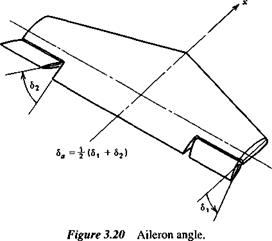
The angle of bank of the airplane is controlled by the ailerons. The primary function of these controls is to produce a rolling moment, although they frequently introduce a yawing moment as well. The effectiveness of the ailerons in producing rolling and yawing moments is described by the two control derivatives dCJd8a and ЭC„/d8a. The aileron angle 8a is defined as the mean value of the angular displacements of the two ailerons. It is positive when the right aileron movement is downward (see Fig. 3.20). The derivative dC/d8a is normally negative, right aileron down producing a roll to the left.

Roll Control

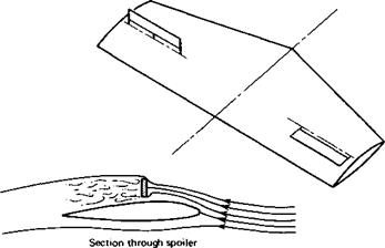
For simple flap-type ailerons, the increase in lift on the right side and the de­crease on the left side produce a drag differential that gives a positive (nose-right) yawing moment. Since the normal reason for moving the right aileron down is to ini­tiate a turn to the left, then the yawing moment is seen to be in just the wrong direc­tion. It is therefore called aileron adverse yaw. On high-aspect-ratio airplanes this tendency may introduce decided difficulties in lateral control. Means for avoiding this particular difficulty include the use of spoilers and Frise ailerons. Spoilers are il­lustrated in Fig. 3.21. They achieve the desired result by reducing the lift and increas­ing the drag on the side where the spoiler is raised. Thus the rolling and yawing mo­ments developed are mutually complementary with respect to turning. Frise ailerons diminish the adverse yaw or eliminate it entirely by increasing the drag on the side of the upgoing aileron. This is achieved by the shaping of the aileron nose and the choice of hinge location. When deflected upward, the gap between the control sur­face and the wing is increased, and the relatively sharp nose protrudes into the stream. Both these geometrical factors produce a drag increase.

Roll Control

The deflection of the ailerons leads to still additional yawing moments once the airplane starts to roll. These are caused by the altered flow about the wing and tail. These effects are discussed in Sec. 5.7 (СПр), and are illustrated in Figs. 5.12 and 5.15. P

A final remark about aileron controls is in order. They are functionally distinct from the other two controls in that they are rate controls. If the airplane is restricted only to rotation about the x axis, then the application of a constant aileron angle re­sults in a steady rate of roll. The elevator and rudder, on the other hand, are displace­ment controls. When the airplane is constrained to the relevant single axis degree of freedom, a constant deflection of these controls produces a constant angular displace­ment of the airplane. It appears that both rate and displacement controls are accept­able to pilots.

INFLUENCE OF FIN ON Clp

The sideslipping airplane gives rise to a side force on the vertical tail (see Sec. 3.9). When the mean aerodynamic center of the vertical surface is appreciably offset from the rolling axis (see Fig. 3.19) then this force may produce a significant rolling mo­ment. We can calculate this moment from (3.9,3). When the rudder angle is zero, that is, Sr = 0, the moment is found to be

ap(~P (t) ~ VpSFzF

INFLUENCE OF FIN ON Clp Подпись: M2 v)

thus

and

Подпись: Эсг SFzF / VA2INFLUENCE OF FIN ON Clp(3.12,1)

INFLUENCE OF FUSELAGE ON Clft

The flow field of the body interacts with the wing in such a way as to modify its di­hedral effect. To illustrate this, consider a long cylindrical body, of circular cross sec­tion, yawed with respect to the main stream. Consider only the cross-flow component of the stream, of magnitude V/3, and the flow pattern which it produces about the body. This is illustrated in Fig. 3.17. It is clearly seen that the body induces vertical velocities which, when combined with the mainstream velocity, alter the local angle of attack of the wing. When the wing is at the top of the body (high-wing), then the angle-of-attack distribution is such as to produce a negative rolling moment; that is, the dihedral effect is enhanced. Conversely, when the airplane has a low wing, the di­hedral effect is diminished by the fuselage interference. The magnitude of the effect is dependent upon the fuselage length ahead of the wing, its cross-section shape, and the planform and location of the wing. Generally, this explains why high-wing air­planes usually have less wing dihedral than low-wing airplanes.

INFLUENCE OF SWEEP ON Clp

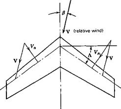
Wing sweep is a major parameter affecting C, . Consider the swept yawed wing illus­trated in Fig. 3.18. According to simple sweep theory it is the velocity Vn normal to a wing reference line (I chord line for subsonic, leading edge for supersonic) that de­termines the lift. It follows obviously that the lift is greater on the right half of the

INFLUENCE OF FUSELAGE ON Clft

INFLUENCE OF FUSELAGE ON Clft

wing shown than on the left half, and hence that there is a negative rolling moment. The rolling moment would be expected for small j8 to be proportional to

CJ(V2)right – (V2)left] = ClV2[cos2 (Л – P) – cos2 (A + (3)}

= 2CL/3V2 sin 2Л

The proportionality with C, and (3 is correct, but the sin 2Л factor is not a good ap­proximation to the variation with A. The result is a oc Q, that can be calculated by the methods of linear wing theory.