§ 57. Vertical Descent
 So far we have examined helicopter flight with the engine operating. In powered flight the thrust force developed by the main rotor performs the functions of lifting and propelling forces. But how is flight continued in case of engine failure?
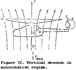
In case of engine failure the helicopter can continue flight only in a descent (vertically downward or along an inclined trajectory). In this sort of flight the propelling force will be the weight force or its component parallel to the flight trajectory. The main rotor will turn, but the turning moment is supplied to the rotor by the aerodynamic forces acting on the rotor blades rather than from the engine. We shall first examine helicopter flight in the autorotative regime along a vertical trajectory (Figure 72).
During steady state vertical descent in the main rotor autorotative regime, the helicopter is acted on by the weight force G, main rotor thrust force T, drag force X of the nonlifting parts of the helicopter, and the tail rotor thrust force T. The helicopter travels vertically downward with the velocity The undisturbed flow approaches the helicopter from below at
this same speed. As this flow passes through the area swept by the main rotor, it is subjected to the action of the blades. The blades of the rotating rotor tend to deflect the approaching stream downward. However, since the
vertical flow velocity V^eg is greater than the induced velocity which the
main rotor blades create, the flow is only retarded rather than deflected
downward. As a result of this retardation, the flow velocity above the
rotor is less than the vertical descent velocity and is equal to the difference
= V^es – V^. Consequently, the mass of air flowing per unit time through
the area swept by the rotor acquires a negative momentum increment mV., which
Ь І
in accordance with the law of momentum conservation will be equal to the main
rotor thrust per unit time, i. e., T = mV., but m = V. Fp, then
ь і ь des
T = FV, pV.. (39)
des і
Thus, the main rotor thrust in the autorotative regime will be larger, the /116 larger the vertical rate of descent and the larger the flow retardation induced velocity.
We shall clarify the conditions for steady state descent in the autorotative regime on the basis of the diagram of the forces acting on the helicopter. These conditions are expressed by the equalities:
G = T + X;
T = S ;
t. r s
M =0, eg
The first condition ensures a constant rate of descent of the helicopter.
The force X is the drag of all the nonlifting parts of the helicopter and acts in the direction of the thrust force; consequently, it retards the downward motion of the helicopter, and therefore, in this case, it cannot be termed the parasite drag force. The larger the force X, the lower the vertical rate of descent. But the drag force of the nonlifting parts is comparatively small and has no significant effect on the vertical rate of descent. Therefore, it can be neglected. Then the first condition is expressed by the approximate equality
For this condition to be satisfied, it is necessary that the helicopter descend at a definite vertical velocity. Formula (39) shows that the thrust force equal to the helicopter weight can be obtained with a lower vertical velocity if the induced velocity is increased by increasing the main rotor pitch. But the main rotor pitch in the autorotative regime cannot be increased arbitrarily. Its magnitude must be strictly defined.
It has been established by experimental aerodynamics that the main rotor thrust in the autorotative regime is approximately equal to the total aerodynamic force R of a flat plate having an area equal to the area swept by the main rotor at an angle of attack of 90° (Figure 73).
Using (40) and (41), we find the helicopter vertical rate of descent
V 20
des / crf? ■

 Since G/F = P (specific loading per unit area swept by the rotor) , takes the form
2 P С#?
|

V des •
Figure 73. Thrust in autorotative regime.
|
|
We see from this formula that the helicopter vertical rate of descent depends on the specific loading on the area swept by the rotor (on the helicopter weight), and on the air density, and therefore on the flight altitude. The vertical rate of descent increases with increase of the specific loading (helicopter weight). This relation can be expressed by the formula
where V. is the vertical velocity for helicopter weight G„;
des2 2
V, is the vertical velocity for helicopter weight G.
des^ 1
With increase of the flight altitude, the air density decreases, which means that the vertical rate of descent increases and can be expressed by the equality
Formula (42) can be simplified if we consider G = 1.2; and p„ ~ kg/sec^/m^.
it u
Substituting these values into (42) , we obtain
 We find the vertical rate of descent of the Mi-1 helicopter in the autorotative regime if
Then ^ез =3.6 13.6 = 13.3 m/sec. This answer shows that a high vertical rate of descent is obtained even for a low specific loading. There are helicopters for which the specific loading on the main rotor reaches values as 2
high as 25 kgf/m. For such helicopters, the vertical descent velocity is 18 m/sec or 65 km/hr.
Thus, during vertical descent in the main rotor autorotative regime the helicopter travels with a high velocity, and landing is dangerous. The conditions for steady state flight in the autorotative regime differ fundamentally from the flight conditions with the engine operating. The difference is that there is no main rotor reactive moment in the autorotative regime. The blade aerodynamic forces do not retard rotor rotation; rather they create the turning moment. Therefore, the helicopter, in contrast with the case of flight with
the engine operating, will turn about the vertical axis in the direction of rotation of the main rotor. To eliminate this turning, the tail rotor must create a thrust directed oppositely to its thrust during flight with the engine operating. The main rotor side thrust force Sg will also be reversed in comparison with the side force during flight with the engine operating.
 the parasite drag force X. propulsive force G^ = G sin 0.


 The maximal power available is obtained at a flight speed from 80 to 100 km/hr for most helicopters.
 1 – main rotor shaft; 2 – slider;


