Category HELICOPTER AERODYNAMICS

In what season of the year can a helicopter climb to the highest altitude and lift the greatest load?

Answer 1» The air density is higher in winter than in summer. With increase of the air density the induced power required for hovering de­creases while the engine power increases. Consequently, in the winter the

excess power AN = N.. – N is greater, which leads to increase of the avaxl req ° ’

static ceiling and lifting capability of the helicopter.

Answer 2. The air density is higher in winter than in summer. Increase

of the air density leads to increase of the power required = m^^F (wR)^.

This means that the excess power AN = N.. – N decreases, and this leads to

avaxl req ’

reduction of the static ceiling and lifting capability of the helicopter.

Answer 3. The air density is higher in winter than in summer. With increase of the flight weight it is necessary to increase the main rotor thrust force, but this involves increase of the reactive moment, which will be the larger, the higher the air density. The conclusion is that in the winter the helicopter must develop more power than in the summer, i. e., the helicopter lifting capability and static ceiling decrease in the winter.

Azimuthal variation of the blade element autorotation conditions in helicopter gliding

Answer 1. During helicopter gliding in the main rotor autorotative regime, the flow conditions about the blade element change continuously. Therefore, the autorotation conditions will also change. The resultant velo­city (=к+ V sin ф) will increase continuously for the advancing blade. This leads to increase of the elementary force AR and to acceleration of the auto­rotation. The resultant velocity of each blade element of the retreating blade decreases and reaches the minimum (W = u – V) at the ф = 270° azimuth. Therefore, the force AR also decreases, and the autorotation will be decelera­ted. Each blade element becomes alternately "driving", then "driven". Most of the elements of the advancing blade will be "driving"; most of those of the retreating blade will be "driven".

Подпись: Да = arctgAnswer 2. During helicopter gliding, the autorotation conditions of each element depend on the blade azimuth. With change of the azimuth there is a change of the element resultant velocity (W=u+V sin ip). At the 90° azimuth this velocity reaches its maximal value, therefore, the angle of attack incre­ment is minimal (Да = arc tg V ^ sin 0/ior + V ^ cos 0) . The force vector AR tilts aft, and the autorotation will be decelerated.

At the 270° azimuth the element resultant velocity is minimal (Да = arc tg

V, sin 0/u – V, cos 0). The forward tilt of the force vector AR will be gl gl

maximal, and the autorotation will be accelerated. The conclusion is that during gliding the retreating blade creates a driving torque and "drives" the advancing blade, which develops a retarding torque.

Answer 3. The blade element characteristics during helicopter gliding are determined by two factors: azimuthal variation of the resultant flow

velocity over the blade element, and the presence of flapping motions and vertical flapping velocity.

At the 90° azimuth the resultant velocity is maximal; the vertical flapping velocity is also maximal and directed upward. The angle

V V

Подпись: Да = arctggl sin 0 – fl

u + V, cos 0
gl

is minimal; therefore, the force vector AR is tilted aft, and the autorotation will be decelerated.

At the 270° azimuth the resultant flow velocity is minimal, and the vertical flapping velocity is maximal, but directed downward. • The angle [4]

is maximal; therefore, the force vector AR is directed forward, and the blade element autorotation will be accelerated.

The conclusion is that the retreating blade develops a driving torque while the advancing blade develops a retarding torque, but the rotor autoro­tation will be steady-state.

Conditions for Blade Equilibrium Relative. to the Horizontal Hinge

Let us examine the blade thrust moment relative to the horizontal hinge.

If this moment is not transmitted to the hub but simply rotates the blade, then a question arises immediately: how is the blade thrust transmitted

through the hinge to the hub? In order to answer this question we examine

Conditions for Blade Equilibrium Relative. to the Horizontal Hinge

the conditions for blade equilibrium relative to the horizontal hinge.

In addition to the thrust force, in the plane perpendicular to the hub /51

rotation plane there act the weight force G^ and the centrifugal force N (Figure 35b).

Each of these forces develops a moment relative to the horizontal hinge.

The blade thrust moment rotates the blade upward. The flapping angle 3 is formed between the blade longitudinal axis and the hub rotation plane. When the blade tip is above the hub rotation plane, the blade flapping angle is considered positive.

The thrust moment rotates the blade in the direction of increasing flap­ping angle (blade flaps upward). The weight moment = G^b rotates the blade downward, reducing the flapping angle. The centrifugal force moment rotates the blade to bring it closer to the hub rotation plane. If the flapping angle is positive, the centrifugal force moment = Nc rotates the blade downward and coincides in direction with the blade weight force moment. If the flapping angle is negative (Figure 35c), the centrifugal force moment rotates the blade upward and coincides in direction with the thrust force moment. Thus the centrifugal force moment tends to reduce the deflection of the blade from the hub rotation plane.

The centrifugal force always acts in the plane of rotation, is directed outward from the axis, and is applied to the blade center of gravity. It is defined by the formula

Conditions for Blade Equilibrium Relative. to the Horizontal Hingegr у Б

The blade centrifugal force of the Mi-4 helicopter at maximal main rotor rpm exceeds 20,000 kgf. Therefore, even with a small arm, c the moment of this force will be very large.

After seeing what moments act on the blade about the horizontal hinge, we can define the equilibrium condition

This condition can he written as follows for positive and negative flap­ping angles:

for g > 0

MT – MQ + MN or Ta – Gb + N – ; <17>

. b

for g < 0

MQ = MT -f – iAft.

Equilibrium in the case of negative flapping angles is possible, hut only in the course of a very limited time. Therefore in the following we shall con­sider (17) to be the equilibrium condition.

If this condition is violated, the blade will rotate until equilibrium is restored at a new flapping angle. With change of the flapping angle, there will be a change of the centrifugal force arm and therefore of its moment. /52

Thus the blade will flap upward if the thrust force moment is greater than the sum of the moments of the centrifugal force and the weight force, i. e., for. But with increase of the flapping angle, the moment = Nc will increase and equilibrium will again be established. The same process will take place upon reduction of the flapping angle, but in the reverse direction.

The flapping angle has a comparatively small value — 7 – 10°.

The primary reason for violation of blade equilibrium relative to the horizontal hinge is the variation of the blade thrust and its moment.

The horizontal hinges have snubbers (stops) to limit the blade upward and downward rotation. The lower stop is the blade droop limiter, i. e., the blade rests on this stop if the rotor is not turning, which prevents the blade coming into contact with other parts of the helicopter. The stop has a centrifugal regulator which allows the blade to deflect to negative flapping angles in flight.

The upper stop limits the upward rotation of the blade (flapping angle 25 – 30°). The blade does not reach the limiters in flight, since the centrifugal force moment does not permit the blade to deflect very far from the hub rotation plane.

CLIMB ALONG INCLINED TRAJECTORY

§ 50. General Characteristics of the Climb Regime /10^

Along an Inclined Trajectory

Climb along an inclined trajectory is rectilinear flight of the helicopter with constant velocity and constant angle relative to the horizontal plane.

In this flight regime the helicopter is subject to the weight force, main rotor and tail rotor thrust forces, and the parasite drag force (Figure 67). To determine the flight conditions the helicopter weight force /10- can be broken down into components: G^ perpendicular to the flight path, and

G^ parallel to the flight path and directed opposite the motion.

The main rotor thrust force can also be resolved into the components Y (lift force), P (propulsive force), Sg (side force). The conditions for steady climb are expressed by the equalities

— (rectilinear flight and constant climb angle);

— (constant velocity);

— (absence of lateral displacment of the helicopter);

— (absence of helicopter rotation about its center of

gravity).


Y = G


P


G„ + X 2 par

T„ = S t. r s

EM = 0 eg


CLIMB ALONG INCLINED TRAJECTORY

Figure 67. Forces acting on helicopter in climb.


§ 51. Thrust and Power Required for Climb

The thrust required for climb can be found by using the diagram of the forces acting on the helicopter (Figure 67),

CLIMB ALONG INCLINED TRAJECTORY(31)

where

Gi = G cos 0.; Gz — Gsin9.


Comparing (31) with (26) , we can say that the helicopter parasite drag in climb is practically equal to the parasite drag in horizontal flight at the

*j

same speed. For example, for the Mi-1 in climb (V ^ = 85 km/hr; 0^9°) the

CLIMB ALONG INCLINED TRAJECTORY

slight increase is explained by the fact that during climb the air flow approaches the fuselage at a large negative angle, which leads to increase of the parasite drag force coefficient from 0.009 to 0.0097. The lift force is less during climb than in horizontal flight. The propulsive force during climb will be greater than the propulsive force in horizontal flight by the


magnitude G sin 0. Consequently, in (31) the first term of the radicand is smaller than in (26), while the second term is larger than the second term of (26). Therefore, the thrust required for climb along an inclined trajectory is practically the same as the thrust required for horizontal flight at the same speed.

Подпись:If a helicopter can hover, then it can climb along an inclined trajectory. This conclusion is confirmed by the fact that excess thrust appears in the forward flight regime (Figure 68). Consequently, even with some thrust deficiency for hovering (dashed curve in Figure 68), climb along an inclined trajectory at a speed greater than the minimal horizontal flight speed is possible. This circumstance is utilized in the running helicopter takeoff.

CLIMB ALONG INCLINED TRAJECTORY

The power required for climb is found from the same formula as used to find the power required for horizontal flight

But in this formula the terms may differ from the corresponding terns for the power required for horizontal flight.

During climb N will not differ from the profile power for horizontal flight if the rpm and flight speed are the same.

The induced power in climb is practically equal to the induced power for

»

horizontal flight, since

N. = YV., and Y, = G cos 0 % G. і і cl

But the power required for motion during climb differs considerably from the motion power for horizontal flight

N t = PV = (X + G.) V = X V. + G. V..
mot cl par 2 cl par cl 2 cl

= N „ + AN.

Подпись:mot, h

Climb is possible if there is excess power AN (i. e., the power available exceeds the power required for horizontal flight)

Подпись:

CLIMB ALONG INCLINED TRAJECTORY

N = N, + AN. cl h

Single-rotor Helicopter Control Principles

Helicopter control involves control of the rotation of the helicopter about its principal axes and control of the vertical displacement. On this basis the entire control complex considered as the sum of the pilot’s actions can be divided into longitudinal, lateral, and directional control, and also control of the up-and-down displacement of the helicopter. This division is purely arbitrary, since the pilot’s control actions are unified and are accomplished simultaneously and synchronously. However, this division facilitates study of the control question and corresponds to the construction of the control system, which includes four control loops which are independent of one another and are named the same as the names of the particular control modes.

Lontitudinal control is control of helicopter rotation about the trans­verse axis. It is achieved by the action on the helicopter of the longitudinal

control moments M, which are created with fore-and-aft deflection of the

zcont

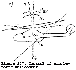
cyclic pitch control stick. As a result of the tilt of the cone-of-revolution axis in the direction of the stick deflection, the main rotor thrust vector tilts. If prior to deflection of the stick the helicopter was in equilibrium, i. e., the thrust force moment was zero (Figure 107a), after forward deflection of the stick the cone-of-revolution axis deflects in the same direction. The thrust force vector passes at the distance a from the transverse axis and creates the thrust moment = Та, which will be a diving moment. In addition
to the thrust moment, the horizontal hinge diving moment Mjjj = Nc is created. The sum of these two moments creates the longitudinal control moment. The helicopter will be rotated about the transverse axis in the nose-down direc­tion under the action of this moment. Aft deflection of the stick leads to the formation of a nose-up pitching moment, under the action of which the helicopter nose rises.

Подпись:

Подпись: Figure 107. Control of single-rotor helicopter.
Single-rotor Helicopter Control Principles

If the helicopter has longitudinal static stability, the rotation will continue until the stabilizer longitudinal moment balances the control moment. If the helicopter does not have static stability, it will be necessary to deflect the stick in the opposite direction to stop the rotation. As a result of helicopter rotation there is a change of the inclination of the thrust force vector and its horizontal component P. This leads to a change of the flight velocity. Hence we can conclude that forward deflection of the cyclic pitch stick leads to lowering of the helicopter nose and increase of the flight speed. Aft deflection of the stick leads to the helicopter nose rising and reduction of the flight speed. If the stick is moved aft while the helicopter is hovering, it will start to move backward. Therefore the operation of the cyclic pitch stick is analogous to the operation of the control stick in an airplane.

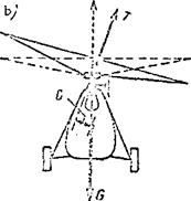
Lateral control refers to control of helicopter rotation about the longitudinal axis. Lateral control is accomplished by deflecting the cyclic pitch stick to the right or left. The main rotor coning axis and the thrust force vector tilt to the same side as the stick (Figure 107b). The deflection of the thrust force vector and the main rotor plane of rotation leads to creation of the lateral control moment as the sum of the moments of the thrust force and the horizontal hinges. The magnitude of the moment will be larger, the higher the main rotor rpm, the larger the stick deflection, and the lower the position of the helicopter center of gravity. Under the in­fluence of the control moment, the helicopter will rotate until the stick is moved in the opposite direction.

Directional control refers to control of helicopter rotation about the vertical axis. The helicopter rotates about the vertical axis under the influence of the directional moment, which is created as a result of the difference of the main rotor reactive moment and the tail rotor thrust moment Mv = M – Mt. Change of the tail rotor thrust force and its moment about the helicopter vertical axis is accomplished by deflecting the directional control pedals. These pedals are coupled by linkage with the pitch change mechanism mounted on the tail rotor gearbox.

If the right pedal is pushed, the tail rotor pitch is increased. As a result of increase of the thrust force by the amount AT, its moment increases. The tail rotor thrust moment becomes greater than the main rotor reactive moment and the helicopter turns to the right. If the left pedal is pushed, the tail rotor pitch is reduced. In view of the decrease of the tail rotor thrust and moment, the latter becomes smaller than the main rotor reactive moment. Under the influence of this moment the helicopter turns to the left.

BASIC CHARACTERISTICS OF THE MAIN ROTOR

§ 4. General Characteristics

The main rotor (MR) is a basic component of a helicopter. It is utilized to create the lift and motive force and to control the helicopter.

The basic parts of the main rotor are the hub and the blades.

The blades create the thrust force that is necessary for flight. The hub connects all the blades and serves to fasten the main rotor to the drive shaft. The drive shaft causes the rotor to rotate.

It is possible to subdivide main rotors into three types depending on the structural arrangement:

Those with rigidly fastened blades;

Those with fully articulated blades;

Those with a semi-rigid (flapping) arrangement.

A main rotor with rigidly fastened blades (Figure 6) has the simplest construction and this is its main advantage. But this rotor has inherent and serious disadvantages, which will be discussed in Chapter IV. Therefore, this type of rotor is not utilized in contemporary helicopters. At present, on some light helicopters, as for example the American helicopters, Hughes UH-6A,

Hiller EH-1100 and others, main rotors with spring fastened blades are used. /J-.Q. These rotors can be considered as a variety of rotor with rigid blades.

BASIC CHARACTERISTICS OF THE MAIN ROTOR

by definite geometric parameters: file shape, blade incidence angle, and the solidity coefficient.


The diameter of the rotor is the diameter of the circle swept out by the blade tips. It is designated by the letter D and the radius R. The radius of a blade element is designated r (Figure 8a). The ratio of the radius of a blade element to the radius of the rotor is termed the relative radius


BASIC CHARACTERISTICS OF THE MAIN ROTOR

BASIC CHARACTERISTICS OF THE MAIN ROTOR

which gives r = rR

The blade planform shape can be rectangular, trapezoidal or a combination (Figure 8b).

In form, the blade resembles the wing of an airplane. The forward edge of the blade is called the leading edge, and the aft edge is called the trail­ing edge.

Trapezoidal blades have the most uniform distribution of aerodynamic /11

forces along the blade. Rectangular blades are simpler to manufacture, but they have several poor aerodynamic characteristics. The most widely used blades are trapezoidal and rectangular in combination.

Подпись: a)Подпись: ВПодпись:The profile of the blade is the term used for the form of the blade section perpendicular to the longitud­inal axis. The profile of a blade resembles the profile of a wing.

Most often double convex asymmetri­cal sections are used (Figure 8c).

The requirements for a blade profile are:

High aerodynamic efficiency,

BASIC CHARACTERISTICS OF THE MAIN ROTOR

Small shift of center of pres­sure with changes in angle of attack;

The ability to autorotate over a considerable range of angles of attack.

The profile of the blade is characterized by the relative thick­ness о = c/b and the relative camber f = f/Ъ (Figure 9).

BASIC CHARACTERISTICS OF THE MAIN ROTOR-p.__ n j According to the relative thick-

Figure 9. Blade profile parameters. °

ness, the profile is classified as

thin (c < 8%), medium (c = 8 – 12%), or thick (c > 12%). Most blades have

a relative thickness of c > 12%. The use of thick profiles allows an in­crease in the force resistance of an element and the stiffness of the blade.

In addition, the aerodynamic efficiency depends less on the angle of attack for thick profiles. This peculiarity of the profile improves the blade properties in the autorotation regime. Generally, the outermost element of the blade has a greater thickness ratio than at the root.

A relative camber of the blade of f = 2 – 3% brings the profile form /12

closer to symmetry, which leads to a decrease in the shift of the center of pressure with changes of angle of attack.

The incidence angle of the blade element is termed the angle ф; it is formed by the angle between the element chord and the plane of rotation of the main rotor hub (Figure 10) . The incidence angle is often called the pitch of the blade element. This is an arbitrary definition. In a more strict definition the pitch of the blade element is the distance H. This distance is obtained from the distance a blade element travels parallel to the chord after one revolution of the main rotor

H = 2ттг tan ф

Owing to the fact that the pitch of a blade element depends only on the incidence angle ф, then in the subsequent discussion we will identify the con­cept "incidence angle" with the concept "blade element pitch". At different elements of the blade the incidence angles will be different.

The pitch of the blade is taken as the incidence angle, or the pitch of the blade element, with a relative radius of r = 0.7. This angle is defined as the incidence angle (pitch) of the main rotor.

Подпись: Figure 10. Incidence angle of the blade. As the blade turns relative to the longitudinal axis, the incidence angle changes. Such turning is possible thanks to the presence of the axial hinge. Consequently, the axial hinge of the main rotor blade is intended for pitch alteration.

The alteration of the pitch of the blade elements over the radius of the main rotor is termed the geometric twist of the blade.

At the root of the blade elements, the incidence angles are the largest, while at the tip they are the smallest (Figure 11). Geometric twist improves the operating conditions of the blade elements, and the angles of attack approach the optimum. This causes an increase of the thrust force of the lift­ing rotor of 5 – 7%. Therefore, geometric twist increases the useful loading of the helicopter at constant engine power.

Owing to geometric twist a more uniform force loading on the blade element is achieved and the speed, at which flow breakdown occurs on the retreating blade, is increased. The majority of blades have a geometric twist which does not exceed 5-7°

Stiffness is understood to mean the ability of the blade to retain its /13 form. With great stiffness, even force loading is not capable of deforming the structure and external shape of the blade. With small stiffness the blade becomes flexible and easily yields to deformation, that is, the blade is strongly bent and twisted. If the flexibility is too great, the optimum

&ч>

Подпись:Подпись: іBASIC CHARACTERISTICS OF THE MAIN ROTORПодпись: in.6. 4 – 2 • О –

-г –

twist cannot be maintained on the blade. This leads to inferior aerodynamic characteristics of the main rotor.

In order to obtain great stiffness, it is necessary to increase the size of the load supporting elements, which leads to increased weight of the blade. Unnecessarily high stiffness leads to an increase of vibration of the main rotor.

The greatest stiffness is obtained with blades of metal or of continuous wooden construction, but the latter are very heavy and are utilized only on light helicopters.

BASIC CHARACTERISTICS OF THE MAIN ROTOR

The area swept out by the main rotor is the area of the circle described by the blade tips

This characteristic of the main rotor has approximately the same impor­tance as the wing area of a fixed wing airplane, that is, it is similar to the lifting surface area.

The disk loading, based on the swept area, is defined as the ratio of helicopter weight to area, that is, the area swept out by the main rotor.

Подпись: /> =G_ F •

2

where, P = specific loading, kgf/m ;

G = helicopter weight, kgf;

„ 2 F = swept area, m.

Contemporary helicopters have specific loadings that vary from 12 to 25 kgf. m2 (or 120 – 150 N/m2).

The solidity coefficient is equal to the ratio of the total planfrom area of all the blades to the area swept out by the main rotor.

Подпись: aSBk

F

where, = planform area of one blade, m ;

D

к = number of blades

Contemporary main rotors have perhaps from 2 to 6 blades. Most often there are 3-4 blades on light helicopters and 5-6 blades on heavy heli­copters. The space factor has a value from.04 to.07. This means that 4 – 7% of the area swept out by the rotor is taken up by the blades. The larger the space factor, within the limits indicated, the larger the thrust developed by the rotor. But if the space factor exceeds.07, then the forces of resistance to rotation are increased and the blade efficiency of the main rotor is decreased.

Possibility of Loss of Blade Flapping Motion Stability

The main rotor hubs in which the angle between the horizontal hinge axis and the radial line is 90°, i. e. , 6 = 90°, have a serious problem: loss of

flapping motion stability. By loss of flapping motion stability, we mean possible deflection of the blade upward or downward to the horizontal hinge stops. This phenomenon takes place as a result of variation of the blade incidence angles during flapping, together with the presence of a blade lag angle.

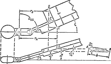
If the blade rotates relative to the vertical hinge through the lag angle then the blade element chord AB will not be parallel to the horizontal hinge axis. During flapping motions, the leading edge and trailing edge of the blade element will displace along two different radii: the point A at the

leading edge will have the larger radius r, the point В on the trailing edge

A

will have the radius r„ (Figure 50).

D

When the blade flaps upward through a certain flapping angle B, the points A and В move up different distances relative to the main rotor hub rotation plane. Point A will move to the height h^, while point В moves to the height hg. As a result of this height difference, the additional angle Да develops /69

between the blade element chord and the hub rotation plane. The larger the blade lag angle and the larger the change of the flapping angle, the larger the incidence angle increase will be.

We see from the figure that

where b is the blade element chord length.

Possibility of Loss of Blade Flapping Motion Stability

Figure 50. Blade pitch change during flapping motions.

The increased height of the leading edge above the trailing edge Ah is found from the formula

Д/г — a tg A£,

where a = b sin £ is the projection of the chord on the radial line. Consequently

i. e., the previously drawn conclusion is confirmed.

If there is a lag angle £, the blade element incidence angle will increase during up-flapping and will decrease during down-flapping. This variation leads to increase of the blade thrust and its moment relative to the horizontal hinge during upward flapping, i. e., the blade will travel up against the stop.

During down-flapping of the blade, blade thrust will decrease still further, which leads to downward travel of the blade against the lower stop.

This is then the manifestation of the loss of flapping motion stability.

How can these undesirable phenomena be eliminated? The simplest technique is to increase the degree of pitch horn compensation, i. e., increase the com­pensation coefficient. However, increase of this coefficient leads to an increase of a particular type of main rotor blade vibration — a vibration of the flutter type. Therefore, the loss of flapping motion stability is elimi­nated at the present time by a different approach — a change of the basic geometry of the main rotor hub.

To accomplish this, a hub is used in which the angle between the horizon­tal hinge axis and the longitudinal blade axis with the blade in the radial

position is less than 90°, i. e., 6 < 90° (Figure 51). Such a hub is

Ші

installed, for example, on the Mi-1 helicopter.

If the blade of such a hub is rotated through the lag angle E, = 90° – 6^ its longitudinal axis is then perpendicular to the horizontal hinge axis.

This means that the radii of rotation about the horizontal hinge for the /70

leading and trailing edges approach one another, i. e., r = rg (see Figure 50).

In this case, flapping motions will not lead to any height increment Ah.

Therefore, there will not be any increase of the incidence angle Ah, and the flapping motions remain stable.

If the lag angle £ 51 90° – 6 , the incidence angles vary just as for

HH

= 90°. However, in this case, the instability of the flapping motions ШІ

Possibility of Loss of Blade Flapping Motion Stability

Figure 52. Schematic of main rotor hub.


Figure 51. Schematic of main rotor hub.

shows up to a lesser degree.

However, if the vertical and horizontal hinges of the main rotor are located in the reverse order, the factors which cause loss of flapping motion stability can be completely eliminated (Figure 52).

With this hinge arrangement, rotation of the blade about the vertical hinge does not cause any change of the position of the blade element chord relative to the horizontal hinge axis.

Consequently, for this hub the radii of rotation of the leading edge and

trailing edges about the horizontal hinge axis will always be the same,

(r. = r„) , i. e., there will not be any change of pitch during flapping motions, A 15

and loss of flapping motion stability will not occur.

Blade Aerodynamic Forces

In order to understand the essence of main rotor operation in the auto­rotative regime, it is necessary to examine the aerodynamic forces which arise on the blade element. In the autorotative regime, each blade element has two velocities: the circumferential velocity u = шг and the vertical descent

velocity (Figure 74a). The sum of these velocities yields the resultant

velocity W = u + The air stream approaching the blade from the side has

a direction opposite the blade element resultant velocity vector.

Подпись: /119As a result of this flow pattern, the air pressure on the bottom of the blade will be higher than that above the blade. The total aerodynamic force AR is created on the blade element. This force may be directed forward at the angle у relative to the main rotor hub rotation axis (Figure 74b); parallel to the hub axis (Figure 74c); or back at the angle у relative to the hub axis (Figure 74d). In the first case, the projection ( – AQ) of the force AR on the hub rotation plane will be directed along the rotation of the main rotor and forms a turning moment under the action of which the main rotor rpm will increase.

In the second case, the projection of the force AR on the hub rotation plane will be zero (AQ = 0). Therefore, the force AR will have no retarding or accelerating effect on the rotation of the main rotor.

In the third case, the projection AQ of the force AR on the hub rotation plane will be directed aft, opposite the rotor rotation, and creates a retard­ing moment under the influence of which the main rotor rpm decreases. This

Blade Aerodynamic Forces

Figure 74. Tilt of force ДК. as a function of main rotor pitch.

means that the nature of the main rotor rotation is determined hy the direction of the elemental forces which develop on the blade.

Losses of the Real Rotor

We have been examining the operation of an ideal main rotor, i. e., a rotor in which all the power obtained from the engine was converted into work

in accelerating the air downward or in creating thrust.

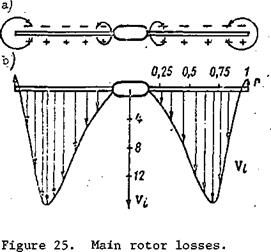
Losses of the Real RotorWe have assumed that the entire area swept by the rotor participates in creating thrust. This means that the increased air pressure below the rotor and the reduced air pressure above the rotor (Figure 25a) acts on the entire main rotor area. In reality, as will be shown later, the entire swept area does not participate in creating thrust. The ideal rotor accelerates a uniform air jet downward with the same induced velocity for all the blade elements. The real rotor provides a swirling jet, and the induced velocities will vary markedly along the radius for the different blade elements (Figure 25b).

The ideal rotor does not expend energy in overcoming friction forces, while the real rotor experiences profile drag forces resisting rotation, and considerable power is expended in overcoming these forces. Moreover, the real rotor has the so-called tip and root losses. The essence of these losses lies in cross-flow of the air from the high-pressure region below the rotor into the low-pressure region above the rotor. This cross-flow takes place through the ends of the blades (tip losses) and through the root sections of the blades near the main rotor hub (root losses), where the structural part of the blade (spar) does not have a lifting surface. The concept of the end loss coefficient x has been introduced to account for the tip and root losses. With account for this coefficient, the actual area participating in creation of thrust is defined by the formula

For most main rotors x = 0.90 – 0.92.

Подпись:Since for the real rotor varies along the radius, we take as the induced velocity its value at the radius r = 0.7

To account for the influence of the profile drag forces, we assume that the real rotor power required for creating thrust is greater on the average than the ideal rotor power required by 25%.

With account for these losses, the thrust of the real rotor can be found from the formula

T~2yFoVl

Hence, it is easy to find the induced velocity in the hovering regime

7

2/Fp *

Knowing that

T = CTF-^-u

Losses of the Real Rotor
Losses of the Real Rotor Losses of the Real Rotor

we obtain

For most main rotors, the induced velocity in the hovering regime is V«8—10 m/sec, and Cx« 0.003.

An important characteristic of the main rotor is the relative efficiency Ni

The main rotor relative efficiency is the ratio of the power required to create the thrust of the ideal rotor to the total power supplied to the rotor. For modem rotors, the efficiency is 0.6-0.75.

HELICOPTER HORIZONTAL FLIGHT

§ 44. General Characteristics of Horizontal Flight /88

Rectilinear flight of a helicopter with constant velocity in the horizontal plane is termed horizontal flight. This is the primary flight regime for the helicopter. Since the Earth is a sphere, flight at constant altitude takes place along a curvilinear trajectory. But the radius of curvature of the Earth’s surface is so large that the curvature of the Earth’s surface can be neglected in flight.

Only in flights on supersonic airplanes at a speed 2-3 times that of sound is it necessary to consider the Earth’s curvature. We shall use an example to demonstrate this. An airplane is flying horizontally at a speed of 1000 m/sec or 3600 km/hr. The airplane weighs 10,000 kgf. Let us find the centrifugal force which arises as a result of curvature of the Earth’s surface

„3

г – mV Fc " R

where m is the airplane mass, kg;

V is the airplane speed, m/sec;

R is the radius of the Earth, equal to 6 370 000 m.

Then

F

с


= 1570 N,


or Fc = 161 kgf.


We see from the example that the Earth’s curvature should be considered when flying at 1000 m/sec, since the airplane lift becomes 161 kgf less than its weight. But for the same flight weight and a velocity of 180 km/hr the centrifugal force is 0.4 kgf.

Therefore, in the following we shall consider the Earth’s surface to be

flat.

HELICOPTER HORIZONTAL FLIGHT HELICOPTER HORIZONTAL FLIGHT

The following forces act on the helicopter in horizontal flight: weight /89

The horizontal flight conditions are expressed by the equalities

Y = G or G – Y = 0;

P =~X or P-X =0; par par

T = S or T – S = 0; t. r s t. r s

ГМ = 0. /L eg

The first condition ensures constant flight altitude, the second provides constant velocity, and the*third specifies linearity of flight in the horizontal plane.

The forces Y, P, Sg are the components of the main rotor thrust. Accordingly, the main rotor thrust in horizontal helicopter flight performs the functions of propulsive, side, and lifting forces.