Category Helicopter Test and Evaluation

Vertical velocity derivatives

These are also known as the angle of attack derivatives as this is proportional to the vertical velocity for a fixed wing aircraft at a given forward speed. Angle of attack is not quite so clearly defined for a helicopter, but the derivatives are still known by either name. The derivatives are Xw (or X„), Zw (or Z„), Mw (or Ma) and the ‘downwash lag’ derivative Mw.

(1) Forward force due to vertical speed (Xw). The force Xw is usually small and insignificant and has little or no effect on either the static or dynamic stability characteristics of the aircraft.

(2) Vertical force due to vertical speed (Zw). An increase in w means that the helicopter is moving vertically downwards, and this causes an increase in the blade angle of attack. This in turn produces an increase in blade lift as the inflow through the rotor decreases. The consequent increase in rotor thrust tends to nulify the increase in w, and Zw is therefore the vertical damping derivative which is an important vertical response parameter, particularly in the hover and at low forward speeds. The force Zw is always stabilizing (negative) and increases from its value in the hover to reach a limiting value in forward flight.

(3) Pitching moment due to vertical speed (Mw). The moment Mw is a measure of the static stability of the rotor with respect to changes in angle of attack. In the hover Mw is zero, but in forward flight an increase in w produces an effective increase in blade lift which is greater on the advancing blade than on the retreating blade. This causes a backwards tilt of the rotor and a nose-up pitching moment. Consequently, the rotor contribution to Mw is positive and destabilizing. Its value increases approximately linearly with speed. Contributions to Mw also come from the fuselage and the horizontal stabilizer. The former is likely to be destabilizing, whereas the latter will normally be stabilizing. The tailplane will however be ineffective in the hover and at forward speeds when it is working in the downwash from the main rotor.

(4) Pitching moment due to downwash lag (Mw). As the tailplane is a finite distance away from the main rotor and there will be a small delay between initiation of changes in rotor downwash due to angle of attack changes and their arrival at the tailplane. This is often ignored for simplicity.

4.9.1.2 Pitch rate derivatives

Assume that the helicopter is pitching nose-up with a constant angular velocity, q, and that the rotor is in equilibrium and pitching at the same rate. As the rotor may be regarded as a gyroscope it will be subjected to a precessing moment which would normally tend to tilt it to starboard. However, because of the response lag, the rotor actually tilts forward causing longitudinal forces and moments. This is the source of the aerodynamic damping discussed earlier. The derivatives Xq and Zq are usually taken as negligible, so Mq is the only derivative worthy of note. Mq represents the change of pitching moment with changes in pitch rate. This is the ‘pitch damping’ derivative. When the helicopter pitches nose-up there will be a favourable nose-down moment from the main rotor due to this aerodynamic damping. Thus, the rotor contribution to Mq is stabilizing (negative). Also, the angle of attack of the tailplane is changed producing more tailplane lift or less downforce and hence a favourable nose-down pitching moment providing a stabilizing contribution. There will also be a contribution from the fuselage that is usually stabilizing. Most helicopters will also require some form of augmentation of this damping if good handling qualities are to be achieved.

4.9.2 Control derivatives

Movement of the collective lever and fore/aft cyclic will also affect the motion of the helicopter in the longitudinal plane by altering the forces and moments acting. Collective and longitudinal cyclic pitch angles are denoted by 0c and Bl respectively, and their effect can be shown by the use of collective and cyclic control derivatives.

LONGITUDINAL DYNAMIC STABILITY AND CONTROL RESPONSE

Whilst static stability is concerned with an aircraft’s initial motion following a perturbation, dynamic stability determines the aircraft’s longer-term response to such a disturbance. An aircraft is dynamically stable if, following the removal of a disturbing force, it returns to its equilibrium position. Control response, on the other hand, is concerned with the response of the aircraft to a control input made by the pilot. This section examines the longitudinal dynamic stability and control response of a single main rotor helicopter in both the hover and forward flight. The analysis of the motions is simplified, as before, by assuming that there are no cross-coupling effects. This is rather less easily justified than for fixed wing aircraft, and care must be exercised in this respect. Before looking at the dynamic modes in detail, it is worth reminding ourselves of the derivatives which influence the longitudinal motion.

4.9.1 Longitudinal derivatives

In the longitudinal plane, the variation of X-force, Z-force and pitching moment, M, with respect to forward and vertical velocities, pitch rate and collective and longitudinal cyclic control movements must be considered.

4.9.1.1 Forward velocity derivatives

(1) Forward force due to forward velocity (Xu). The advancing blade sees an increase in forward speed as an increase in relative airspeed whilst the retreating blade see it as a decrease in relative airspeed. Assuming a phase angle of 90°, this causes the rotor disk to flap further back, which in turn causes the thrust vector to tilt rearwards resulting in a decrease in X-force. The flapback also results in an increase in rotor thrust and in Я-force. Fuselage drag also increases with speed and at forward speeds in the range 35 to 50kts this contribution can be equal to that of the main rotor. The overall effect of all these contributions is to return the aircraft to its equilibrium position. To summarize, there are stabilizing contributions to Xu from the backward tilt of the main rotor; the change in magnitude of the thrust vector; the change in fuselage drag; and the change in rotor in-plane force.

(2) Vertical force due to forward velocity (Zu). This derivative is zero in the hover as one would expect, and at low forward speeds an increase in forward speed will cause an increase in rotor lift. However, the amount of disk tilt is an important parameter in the determination of the rotor lift. At high forward speeds the tilt may be large and an increase in speed may then result in a decrease in rotor lift. The force Zu is therefore zero at the hover, becomes negative (remember Z is positive downwards) and then positive. It may be undesirable for Zu to be negative, however, and in this respect an aerodynamically clean fuselage is advantageous as a reduction in overall fuselage drag will result in a smaller disk tilt for a given speed.

(3) Pitching moment due to forward speed (Mu). An increase in forward speed causes the disk to flap back and hence tilts the thrust vector rearwards causing a nose – up pitching moment which gives a stabilizing (positive) contribution to Mu. A horizontal stabilizer also contributes significantly to the overall value of Mu, its effect depending on its setting angle and on the downwash changes resulting from the speed changes. The fuselage can also contribute to Mu, its contribution depending on the change in fuselage lift and drag with changes in speed and the distance of its centre of pressure from the CG. This derivative has a major effect on the dynamic motion of the helicopter and, although a positive value of Mu is necessary for static stability with respect to forward speed changes, if excessive, it will cause dynamic instability.

4.8 MANOEUVRE STABILITY

The response of a rotor to changes in AOA is unstable. Therefore a helicopter would possess negative manoeuvre stability without the addition of a surface to provide a stabilizing moment. A horizontal stabilizer is generally fitted to a helicopter to serve this purpose and thus provide a degree of manoeuvre stability. It will, however, also affect the static stability. Manoeuvre stability, or otherwise, arises from the development of pitching moments following changes in the angle of incidence of the airflow approaching the helicopter. Contributors to manoeuvre stability are:

(1) The main rotor. The main rotor provides an unstable contribution to manoeuvre stability. The size of the destabilizing pitching moment will increase with trim speed, above minimum power speed, and load factor.

(2) The horizontal stabilizer. The horizontal stabilizer provides a stabilizing contri­bution to manoeuvre stability. It does not matter whether the stabilizer is uploaded or downloaded when at the trim condition, since an increase in fuselage incidence will result in a nose-down pitching moment in both cases. The magnitude of the stabilizing moment increases with trim speed, but not load factor.

(3) The fuselage. The contribution to manoeuvre stability from the fuselage can be either stabilizing or destabilizing depending on the line of action of the lift and drag forces.

The destabilizing effect of aft rotor flapping (main rotor contribution to manoeuvre stability) is approximately proportional to the square of the forward speed as is the change in lift generated by the tailplane following an AOA change. Therefore, the size of stabilizer selected to provide stability at one trim speed is generally suitable for other speeds. However, since the magnitude of the destabilizing moment from the main rotor also increases with load factor, but the opposing moment from the horizontal stabilizer does not, it is highly likely that a helicopter will display manoeuvre instability if tested at both high load factor and high speed. A low set stabilizer may also suffer a variation in performance if heavily influenced by the downwash from the main rotor.

The position of the CG relative to the main rotor thrust vector and tailplane has an effect on the manoeuvre stability of a helicopter. If the CG is forward of the rotor, the increase in rotor thrust and aft tilt of the vector associated with an up gust may produce a stabilizing nose-down pitching moment, or at least a less severe nose-up moment. With an aft CG position, however, the situation is reversed and an increase in thrust and rearwards tilt of the thrust vector will generate an unstable pitching moment. The horizontal stabilizer will be required to provide a measure of manoeuvre stability, as described above. The overall stability will be weaker at higher weights and with aft CG positions since the destabilizing effect of the main rotor will be that much stronger. This is usually the reason a maximum allowable aft CG position is quoted in the operating manual. The forward limit is often established by the manufacturer either to prevent high oscillatory rotor loads or to provide adequate aft stick margin for a landing flare or rearward flight.

Climbing and descending flight

In a steady climb the cyclic stick is often held forward to counter the nose-up pitching moment from the tailplane as well as that from the main rotor. A rapid entry into flight idle glide (FIG) or autorotation will have the opposite effect. The amount of aft stick required during a rapid entry is of particular interest especially if there is a danger of infringing control margins. Sometimes even during a steady autorotation there is still concern over the amount of aft cyclic required to counter the net nose – down moment from the tailplane. In such cases the designer may arrange for a reduction in the effectiveness of the stabilizer, thereby reducing the upsetting moment. Measurement of the position of the cyclic stick in steady climbs or descents is part of a test technique called ‘Trimmed Flight Control Positions’ (TFCP) which is discussed later (Section 5.2).

4.7.3 Forward flight

The response of a rotor to changes in speed is stable. Therefore a tail-less helicopter should possess a degree of positive static stability. Since, however, the fuselage contribution to static stability is variable and the addition of a horizontal surface will provide manoeuvre stability most helicopters are fitted with a tailplane at some location on the tail boom. Static (speed) stability, or otherwise, arises from the development of pitching moments following changes in the speed of the airflow approaching the helicopter. In summary, the contributors to static stability are:

(1) The main rotor. The main rotor provides a stable contribution to static stability. The size of the stabilizing moment increases with speed and rotor thrust.

(2) The horizontal stabilizer. The horizontal stabilizer produces a stabilizing contri­bution to static stability provided that it is downloaded. Therefore the inherent stability of the isolated main rotor (with speed) can be increased, or reduced, by the addition of a suitably sized downloaded, or uploaded, tailplane. The magnitude of the moment from the tailplane increases with speed.

(3) The fuselage. The contribution to static stability from the fuselage can be either stabilizing or destabilizing depending on the line of action of the lift and drag forces.

LONGITUDINAL STATIC STABILITY

The main rotor, the fuselage and the horizontal stabilizer are assumed to be the only contributors to the longitudinal stability of the helicopter. Before going further it is worthwhile revising two important stability definitions:

(1) Trim. An aircraft is in trim when all the forces and moments acting on it are in balance. The aircraft is in a state of equilibrium and would continue in that condition unless acted upon by a gust, or affected by pilot action.

(2) Static stability. A body is statically stable if there is an initial tendency for it to return to its trim condition after an angular displacement or after a change in the transitional velocity. In helicopter parlance static stability, in forward flight, describes the response of the helicopter following a change in translation velocity (speed stability). Manoeuvre stability is the response to angular changes (AOA stability).

4.7.1 Hovering flight

Evidently a helicopter possesses neutral static stability with respect to angular displace­ments when the definition of static stability, given above, and the rotor response, detailed earlier, are considered. If a helicopter suffers an angular disturbance while hovering no direct aerodynamic moment arises which will restore it to its original attitude. The resultant rotor thrust always passes through the centre of gravity irrespective of the angular position of the helicopter (assuming no download on the horizontal stabilizer and fuselage). The response is equivalent to the neutral stability in roll displayed by a conventional fixed wing aircraft. In both cases it is the subsequent generation of a translational velocity that may give rise to a stabilizing response. In the fixed wing case the roll disturbance causes a lateral velocity to develop and the dihedral of the wings combined with this velocity produces a moment which will tend to return the aircraft to the trim condition. Similarly for a helicopter the angular displacement will result in a translational velocity due to the unbalanced horizontal component of the thrust vector. The positive speed stability of the rotor will then lead to the development of a moment tending to return the helicopter to the trim position. If a hovering helicopter is subjected to a disturbance in translational velocity then it is only the flap-back effect from the rotor that will tend to return the helicopter to its original attitude. At very low speeds contributions from the horizontal stabilizer and fuselage may be ignored.

4.7.2 Cross-coupling : collective to pitch attitude

Before describing the static and manoeuvre stability in forward flight it is important to understand the effect of changes in collective pitch, at constant airspeed and load factor, on the pitch attitude of the helicopter. The initial response of the helicopter will be dictated by the change in the magnitude, and direction, of the thrust vector and hub moment from the main rotor. As the pilot raises the collective lever the lift produced by all blades is increased thereby increasing the thrust and the coning angle. In forward flight the increased collective pitch will have a greater effect on the advancing side and consequently the amount of nose-down longitudinal flapping will be reduced. The net result of these changes is to reduce the size of the nose-down pitching moment generated by the main rotor. The helicopter will, therefore, pitch nose up as the collective lever is raised. Subsequent control activity and cyclic stick displacement from the level flight position will result from the effect of the relative airflow on the horizontal stabilizer and fuselage.

Rotor flapping and disk tilt

Consider a helicopter hovering in still air. If the longitudinal airspeed of the helicopter is changed from zero, by a gust or pilot inaction, the disk will tilt upward over the nose if the airspeed change is positive, that is forward, and vice-versa. This phenomena, the ‘flap-back effect’, is very important in determining the static stability of the helicopter. Alternatively if the helicopter is allowed to sink the change in inflow will cause the rotor to generate more thrust thereby arresting the descent. In a similar manner a climb initiated by a gust will be damped out. Suppose a gust strikes the fuselage causing it to pitch up. This will have the initial effect of changing the pitch on the blades since the rotor will initially retain its position in space due to gyroscopic rigidity. Although the pilot has not applied any cyclic pitch a movement of the fuselage relative to the main rotor will have the same effect. Shortly after the fuselage pitches up the rotor will follow it and ultimately be re-aligned, at which point the lift will be equalized once again.

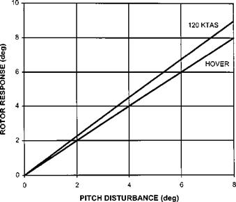
The response of the rotor to a change in forward airspeed, whilst in forward flight, is similar to that for the hover. The changes in lift on the advancing and retreating sides of the disk cause it to tilt up over the nose following an increase in airspeed and vice-versa (flap-back). The effects of changes in vertical speed and fuselage pitch attitude are different, however, with both situations giving rise to an unstable disk response. Suppose the helicopter develops a positive vertical speed (downwards). This will generate an increase in the angle of attack on both sides of the disk and hence an increase in lift. This increase is, however, not equal and the net result will be an upward tilt of the disk over the nose of the helicopter. The tilt back of the rotor will have the effect of increasing the AOA. If the action of a gust causes the helicopter to pitch nose-up this will increase the pitch of the advancing blade and reduce the pitch of the retreating blade as already described. The rotor will then flap in a ‘nose-up’ direction to achieve equality of lift, again as already mentioned. However due to the effect of the forward speed the attitude of the rotor relative to the fuselage at the point of lift equalization is further nose-up than the original disturbance. The tilt back angle required to equalize lift for a given pitch disturbance is determined in Table 4.8 and plotted in Fig. 4.19. For simplicity the rotor has a symmetric blade section and is initially at zero collective pitch (blade flapping is not considered). Note in this simple example that the blade pitch, measured relative to the horizon, is controlled solely by the swash plate tilt.

Table 4.8 Disk tilt response to a pitch disturbance (120 kts, rotor radius 6.5 m, RRPM 35 rad/s).

Total

velocity

vector

)R

(m/s)

V

(m/s)

angle

(deg)

C (deg)

h (deg)

a (deg)

L/S

(N/m2)

start

227.50

289.2

0.0

0.0

0.0

0.0

0

A

start

227.50

165.8

0.0

0.0

0.0

0.0

0

R

body tilt

227.50

289.2

0.0

0.0

10.0

10.0

102475

A

body tilt

227.50

165.8

0.0

0.0

-10.0

-10.0

– 33 663

R

disc tilt

227.50

288.5

7.9

10.0

10.0

2.1

21 709

A

disc tilt

227.50

167.1

-13.7

-10.0

– 10.0

3.7

12 577

R

lift equal

227.50

288.4

8.4

10.7

10.0

1.6

15 940

A

lift equal

227.50

167.2

-14.7

-10.7

– 10.0

4.7

15 939

R

image106

Fig. 4.19 Rotor response to a pitch attitude disturbance.

4.6.2 Main rotor contributions to speed and AOA stability

The foregoing discussion of the rotor response to changes in flight condition gives insight into the stability of a helicopter. Recalling that static stability is the initial response of the aircraft following a disturbance it is possible to lead from a considera­tion of speed and AOA stability to static stability. Before describing the stability of a conventional helicopter it will instructive to introduce the mechanisms by which control is effected. The basic method of control is through the generation of moments about the centre of gravity. In this case only pitching moments derived from the main rotor will be considered. On all helicopters a control moment is generated by changing the direction and magnitude of the thrust vector. Changes to the direction are achieved by disk tilt. An additional moment will arise on helicopters with a non-zero hinge offset, since as the disk tilts relative to the fuselage, centrifugal forces acting on the blades give rise to a couple which manifests itself as a hub moment which is proportional to the amount of disk tilt. Therefore, regardless of the type of rotor system, if a disk tilt is produced as a response to a disturbance a moment, pitching in this case, will be generated. Suppose the pilot trims the helicopter at a particular airspeed and then relaxes on the controls. Sometime later a gust strikes the aircraft causing the airspeed to increase. This increase will cause the rotor to flap-back, that is the disk will tilt rearwards. The movement of the disk relative to the fuselage will generate a nose-up pitching moment that will have the effect of reducing the airspeed. Therefore the main rotor generates a stabilizing contribution to the overall speed stability of the helicopter. Again suppose the pilot trims the helicopter, but this time the disturbance generates either a downwards component of airspeed or causes the fuselage to pitch upwards. In either case the result is an increase in the AOA on the advancing blade. Once again the rotor disk will tilt rearwards but this time further than the original AOA disturb­ance, thereby producing a net out-of-balance moment which generates a further disturbance. Therefore the main rotor generates a destabilizing contribution to the overall AOA stability of the helicopter.

ROTOR CONTRIBUTIONS TO STATIC AND DYNAMIC STABILITY. Changes to blade lift

The basic aerodynamics of rotor blades are similar to a conventional wing. At a given radial location the lift generated will depend on the flow velocity and incidence. The actual flow velocity and incidence will arise from the interaction of the rotational speed of the rotor, the inflow velocity, the airspeed, rate of climb or descent of the vehicle and the pitch setting of the blades. The variation of lift with changes in airspeed, vertical speed and blade pitch are best discussed by example. For simplicity this discussion will be restricted to the advancing and retreating blade tip (r = R and ^ = 90° and 270°). Consider a hovering rotor that is subjected to the following:

at = 90° and a reduction at = 270°, will result. This will change the AOA in a similar sense resulting in more lift being generated at ^ = 90° and less at ^ = 270°.

Now consider the same three disturbances applied to a rotor in trimmed forward flight with the cyclic pitch arranged to equalize the lift produced around the azimuth.

(1) Disturbance along the longitudinal axis. Suppose the rotor is subjected to a disturbance equivalent to the rotor developing a forward airspeed increment. The effect of the disturbance is similar to that observed in the hover: more lift is generated on the advancing side and less on the retreating side.

(2) Disturbance along the vertical axis. If the rotor develops a sink rate the inflow velocity component is reduced and the AOA consequently increased. Since the rotor is now in a combination of pure vertical flight and forward flight the increase in lift is not equally distributed around the azimuth due to the advancing/retreating effect.

(3) Change in blade pich. As before suppose the rotor is disturbed such that the swash plate is moved instantly and the rotor attitude is initially unchanged. If the swash plate is tilted nose-up an increase in blade pitch at ^ = 90°, and a reduction at ^ = 270°, will result. This will change the AOA in a similar sense resulting in more lift being generated at ^ = 90° and less at ^ = 270°. The resulting change in the pitch attitude of the rotor is discussed below.

Calculations can be made to illustrate precisely how changes in airspeed, rate of climb or descent and pitch affect the lift generated on a blade. A rotor of 5.5 m radius, rotating at 35 rad/s and with a lift curve slope of0.1/deg was used to produce the data contained in Tables 4.6 and 4.7.

The changes in lift described in these tables will cause the rotor blades to move about their flapping hinge, or bend within their flapping flexural element. An increase in lift will cause the blade to flap upwards and vice-versa. A rotor can be considered as a heavily damped system operating at (or close to) its natural frequency and therefore there will be approximately a 90° phase lag between input and output. The net result is that if an increase in lift reaches its maximum value at the point of maximum tangential velocity the blade will reach the point of maximum upwards flapping over the nose, that is approximately 90° later.

Table 4.6 Variations in lift:hover.

Disturbance

h(deg)

Tangential speed (m/s)

vi (m/s)

V (m/s)

a (deg)

L/S

(N/m2)

nil

5.00

227.50

10.00

227.72

2.48

7887

5 kts fwd

5.00

230.07

10.00

230.29

2.51

8157

A

5 kts fwd

5.00

224.93

10.00

225.15

2.45

7621

R

100 fpm descent

5.00

227.50

9.49

227.70

2.61

8291

+ 0.5 deg pitch

5.50

227.50

10.00

227.72

2.98

9475

A

+ 0.5 deg pitch

4.50

227.50

10.00

227.72

1.98

6299

R

Table 4.7 Variations in lift: 120 kts.

Tangential L/S

Disturbance

h(deg)

speed (m/s)

vi (m/s)

V (m/s)

a (deg)

(N/m2)

nil

3.52

289.23

10.00

289.40

1.54

7889

A

nil

8.12

165.77

10.00

166.07

4.67

7889

R

5 kts fwd

3.52

291.80

10.00

291.97

1.56

8121

A

5 kts fwd

8.12

163.20

10.00

163.51

4.62

7558

R

100 fpm descent

3.52

289.23

9.49

289.38

1.64

8403

A

100 fpm descent

8.12

165.77

9.49

166.04

4.84

8181

R

+ 0.5 deg pitch

4.02

289.23

10.00

289.40

2.04

10454

A

+ 0.5 deg pitch

7.62

165.77

10.00

166.07

4.17

7044

R

Semi-rigid rotors

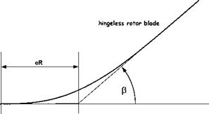
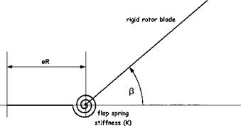
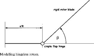
The flap behaviour of a semi-rigid rotor can be modelled by approximating the rotor system to one with a hinge offset and a spring force. The size of the hinge offset, now referred to as the effective hinge offset, is chosen so that blade flap mode shape equates to the real blade under out-of-plane bending, see Fig. 4.18. Now the basic flapping equation is given by Equation (4.19) as:

Iyy P + ) 2 (Iyy + mb Xg eR2 )P = MA

image101

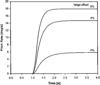
Fig. 4.16 Effect of hinge offset on pitch rate response.

image102

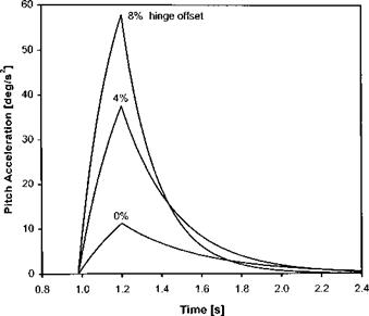
Fig. 4.17 Effect of hinge offset on pitch acceleration.

The spring produces a restoring moment proportional to the flap angle, thus Equation (4.19) becomes:

Iyy p + n2(Iyy + mb Xg eR2 )p + KpP = MA (4.37)

image103

Fig. 4.18


image104image105

In order to determine the effect of this extra moment consider the case when the blade is disturbed in the flapping sense whilst in the hover. As before the aerodynamic moment is given, from Equation (4.20), by:

Мк у

~T =-у(1 – e)3(1 + e/3)np

lyy 8

Thus substituting into Equation (4.37):

Iyy p + 8(1 – e)3(l + e/3)Iyy )p + Q.Iyy + mb Xg eR2 )p + KpP = 0

or:

mb Xg eR[5] [6] [7]

Подпись: n = 8(1 - e)3(1 + e/3) Подпись: УУ Semi-rigid rotors

p + n )p + )2(1 + s + k)P = 0 where:

Taking Laplace transforms:

^2 + n )s + )2(1 + s + k) = 0

Semi-rigid rotors Подпись: ) V1 + s + к and £ Подпись: n 2V1 + s + к

Comparing with the standard second-order characteristic equation:

The above equations indicate that the presence of the spring increases the natural frequency and reduces the flap damping. This is exactly the same effect as caused by increases in hinge offset, therefore a hingeless rotor may be adequately represented by a fully articulated rotor with a hinge offset greater than the geometric equivalent, as in Fig. 4.18.

Variation of control power with hinge offset

It has already been shown that a flapping hinge offset results in an increase in aerodynamic damping. Flight experience suggests that rotors with large hinge offsets also have a high degree of control sensitivity. In other words such a rotor causes a rapid acceleration in pitch and roll which combined with the high damping gives short time constants. Thus a rotor with a large hinge offset will display a crisper control response than one with a small offset; a steady pitch or roll rate being achieved rapidly after the application of step control input. The reason for this differing response lies in the fact that the hinge offset itself gives rise to additional forces and moments that

image99

Fig. 4.14 Offset flapping hinges.

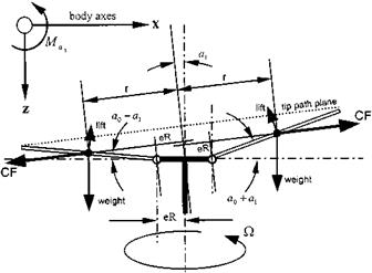
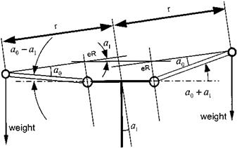
accelerate the aircraft in pitch or roll. From Fig. 4.14 it can be seen that as the blade flaps the lines of action of the centrifugal forces are no longer coincident; thus a couple is produced. This couple produces a moment at the hub that reinforces the disk tilt demanded by pilot control input: nose-up disk tilt produces a nose-up hub moment.

The hub moment arises from the separation between the lines of action of the centrifugal loads on opposite blades. In the longitudinal sense the separation is a function of the magnitude of a1. Thus from Fig. 4.15 the maximum moment per blade is:

M = 2CFeR tan a1 (4.34)

image100

Now:

CF = mb r() cos a1 )2

where r is the radial location of the centre of mass from the axis of rotation.

For a blade with a uniform mass distribution:

CF = mbieR + 2(1 — e)Rcos a0 j)2 cos2 a1 (4.35)

Hence using Equations (4.34) and (4.35):

Подпись: )2 cos2 a1 tan a1M = eRmbieR + 2(1 — e)R cos a0

Assuming a small coning angle and disk tilt; tan a1 = a1 and cos a0 = cos a1 = 1:

M = eR2mb (1 + e) )2a1

The average longitudinal moment is obtained by noting that the moment varies from the maximum value given above to zero. Thus since the longitudinal moment will only arise from longitudinal flapping and for b blades:

be

M = y(1 + e)mbR2 )2a1 (4.36)

Now the control power is defined as the moment generated for maximum control deflection, thus from Equation (4.36):

Mai = dM = 2 ebR2mb (1 + e) )2

Hence the larger the hinge offset the larger the additional moment. Thus it is now possible to describe the control response of a rotor with a hinge offset. When compared with a teetering rotor, a rotor with a significant hinge offset will display a larger control sensitivity since the additional moment described above will reinforce the moment achieved by tilting the thrust vector so giving a greater angular acceleration. The higher aerodynamic damping associated with hinge offset then causes the accelera­tion to decay rapidly. Thus the time to steady pitch or roll rate is inversely proportional to the size of flapping hinge offset, see Figs 4.16 and 17.

Flapping motion due to steady pitch or roll rate

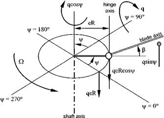
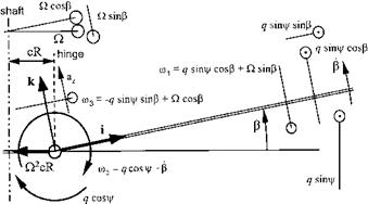
The application of a steady pitch or roll rate (see Fig. 4.9) to a rotor system is an important scenario since it introduces not only the concept of rate cross-coupling but highlights the existence of aerodynamic damping resulting from the interaction between the main rotor and the fuselage. The following discussion will consider only the flapping motion due to a pitch rate; the situation when a steady roll rate is applied can be tackled in an analogous manner. The analysis begins by returning to the basic flapping equation (4.19):

Iyy m2 – Iyy m1 m3 – mbXgRaz = M

From Fig. 4.10, it can be seen that:

m1 = q sin ^ cos p + ) sin p t

m2 = q cos ^ — p > (4.26)

m3 = — q sin ^ sin p + ) cos P J

Therefore for a constant pitch rate:

m 2 = q cos ^ — qvjr sin^ — p = q cos ^ — q) sin ^ —p = —q) sin ^ —p (4.27)

image93

image94

Fig. 4.10 Rotor axes system under the influence of a steady pitch rate.


In addition, using small angle approximations and assuming q2 is small compared with )2;

image95m3 m1 = (— q sin ^ sinp + ) cos P)(q sin ^ cos p + ) sin p) m3m1 = — q2 sin2 ^p — q) sin ^p2 + q) sin ^ + )2p = q) sin ^ + )2p

Thus substituting Equations (4.27) and (4.28) into Equation (4.9):

Iyy m 2 — Iyy m1 m2 — mb Xg Raz = M — Iyyp — Iyy q) sin ^ — Iyy q ) sin ^ — Iyy )2p — mb Xg Raz = M

Подпись: p + 2q ) sin ^ + )2p +.

mb Xg Raz MA

Подпись: УУУУ

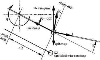
Now the vertical velocity of the hinge as a consequence of the pitch rate can be seen from Fig. 4.11 to equal:

Подпись:

image96

V = )eR sin ^ sin 0 — qeR cos ^ = )eR sin ^0 — qeR cos ^

Flapping motion due to steady pitch or roll rate Подпись: qeR) sin У + qeR) sin У Подпись: (4.30)

Therefore the vertical acceleration, again as a consequence of the pitch rate, will be:

Substitution for the angular velocity components of the blade and the acceleration of the hinge given by Equations (4.11) and (4.30), leads to:

P + )2(1 + s)P = )2 d^ + )2(1 + s)P = – 2)q(1 + s) sin У (4.31)

Uy – lyy

Due to the combination of pitching and flapping, the change in blade incidence at a point r from the flapping hinge is given, for small flap angles, by:

* _ rm2 rq cos У — rp

“ = )(r + eR) = )(r + eR)

Therefore as before:

Подпись: q cos У — p )(r + eR)

Flapping motion due to steady pitch or roll rate

SL = 2 p V2sCL =1 p)2(r + eR)2cr Sr a

Flapping motion due to steady pitch or roll rate Flapping motion due to steady pitch or roll rate

and:

= 2 pac)(q cos У — p)R4(1 — e)3(1 + e/3)

So:

Подпись:M у.

—— = у )(q cos У — P)(1 — e)3(1 + e/3) = n)(q cos У — p)

lyy 8

Flapping motion due to steady pitch or roll rate Подпись: (4.33)

and on substitution of Equation (4.32) into Equation (4.31):

Once again only the steady state result is of interest. Thus if: P = a0 — a1 cos У + by sin У then the solution to Equation (4.33) is given by: qn(3s + 2)

)(S2 + Щ2 )

Подпись: by = —q[2s(s + 1) — щ2]
)(s2 + n2)

n = 8(1 — e)3(1 + e/3)

Consider the case when the hinge offset is zero, e = s = 0, so:

Подпись: qa1 =

Hence for a steady nose-up body pitch rate the rotor develops a nose-down tilt relative to the fuselage. The tilt is proportional to the pitch rate and is inversely proportional to Lock number. A moment is therefore generated via a forward tilt of the thrust vector that opposes the original nose-up moment. Thus the rotor develops aerodynamic damping which in the longitudinal sense will contribute, along with the tailplane, to the magnitude of Mq. Note also that a body pitch gives rise to lateral flapping such that a nose-up pitch produces a disk tilt to port. Hence rate cross-coupling occurs even when the hinge offset is zero, unlike with acceleration cross-coupling. It can be shown that for a uniform blade:

a,) 4y(l – e)4(l + e/3) (5e + 4)

~q~ = [144e2 + y2(1 – e)8(1 + e/3)2]

and

96e(2 + e) – y2(1 – e)8(1 + e/3)2
4y(1 – e)4(1 + e /7) (5e + 4)

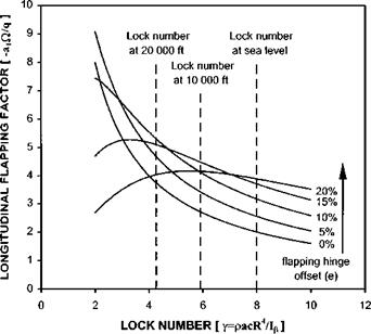
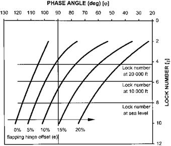
The variation of aerodynamic damping (proportional to a,)/q) and rate cross­coupling with hinge offset and Lock number are presented in Figs 4.12 and 4.13 respectively. Figure 4.12 indicates that at high Lock number the level of aerodynamic damping increases with hinge offset. Figure 4.13 shows that the tendency for the disk

Flapping motion due to steady pitch or roll rate

image97

image98

Fig. 4.13 Example of rate cross-coupling.

to tilt to port with a nose-up pitch rate changes with both Lock number and hinge offset. Recalling that Lock number is air density dependent allows an estimation of the variation of damping and cross-coupling with altitude. If a Lock number of 8 at sea level is assumed then it can be seen that at high altitude the aerodynamic damping will be greater for a rotor of modest hinge offset and the tendency of the aircraft to roll to the left may be replaced by a tendency to roll right, especially at high values of hinge offset. The increase in rotor damping with altitude may appear a little confusing but it should be remembered that the damping arises from the interplay between the tilt of the rotor due to aerodynamic forces and the inertia of rotor due to gyroscopic effects. Hence at high altitude the inertia forces will be stronger and the rotor will have a greater tendency to retain its position in space whilst the fuselage pitches nose up, thereby resulting in a greater relative nose-down disk tilt. Note that the increased off – axis response of a rotor with a high hinge offset at high altitude causes a reduction in aerodynamic damping.