Category MECHANICS. OF FLIGHT

The load factor

In order to allow for the extra loads likely to be encountered during aero­batics, every part of an aeroplane is given a load factor, which varies according to conditions, being usually between 4 and 8. This means that the various parts are made from 4 to 8 times stronger than they need be for straight and level flight.

Turning

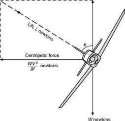
In an ordinary turn (Fig. 8B) the inward centripetal force is provided by the aeroplane banking so that the total lift on the wings, in addition to lifting the aeroplane, can supply a component towards the centre of the turn (Fig. 8.3, overleaf).

Suppose an aeroplane of weight W newtons to be travelling at a velocity of V metres per second on the circumference of a circle of radius r metres, then the acceleration towards the centre of the circle is V2//- metres per second per second.

Therefore the force required towards the centre

= WWgr newtons

If the wings of the aeroplane are banked at an angle of в to the horizontal, and if this angle is such that the aeroplane has no tendency to slip either inwards or outwards, then the lift L newtons will act at right angles to the wings, and it must provide a vertical component, equal to W newtons, to balance the weight, and an inward component, of WV2/gr newtons, to provide the accel­eration towards the centre.

This being so, it will be seen that –

tan в = (WWgr) – t – W = V^-lgr

The load factor

The load factor

Fig 8B Turning

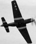
A Mustang making a tight turn near the ground.

This simple formula shows that there is a correct angle of bank, в, for any turn of radius r metres at a velocity of У m/s, and that this angle of bank is quite independent of the weight of the aeroplane.

Consider a numerical example –

Find the correct angle of bank for an aeroplane travelling on a circle of radius 120 m at a velocity of 53 m/s (take the value of g as 9.81 m/s2).

V= 53 m/s

r = 120 m

tan 0= W/gr = (53 X 53)/(9.81 X 120) = 2.38 с. в = 67° approx

What would be the effect if the velocity were doubled, i. e. 106 m/s? tan в would be 4 X 2.38 = 9.52 с. в = 83° approx

What would be the effect if the velocity were 53 m/s as in the first example, but the radius was doubled to 240 m instead of 120 m?

W newtons

The load factor

Fig 8.3 Forces acting on an aeroplane during a turn

The load factor

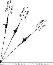
Fig 8.4 Correct angles of bank Radius of turn 50 metres

tan в would be 2.38/2 = 1.19 .•. в = 49° approx

Thus we see that an increase in velocity needs an increase in the angle of bank, whereas if the radius of the turn is increased the angle of bank may be reduced, all of which is what we might expect from experiences of cornering by other means of transport. Figures 8.4 and 8.5 (overleaf) show the correct angle of bank for varying speeds and radii; notice again how the speed has more effect on the angle than does the radius of turn.

Pulling out of a dive

We have already looked at one example involving a pull-out from a dive. Let us now look at some of the effects of this manoeuvre. Firstly, we have seen that the wings will have to generate more lift, in order to provide the necessary cen­tripetal acceleration. This means that the bending stresses in the wing will increase. In fact, in a 3 ‘g’ pull out, they will be three times as high as for normal level flight. Design and safety requirements and regulations will specify the maximum load factor that the aircraft must be able to withstand, and all the stresses in the aircraft have to be determined for this condition. The required load factor will depend on the usage. Fully aerobatic types have a high specified maximum load factor, whereas civil transports have a lower requirement. You are not allowed to roll or loop airliners, although a roll has been performed on at least one occasion (without any passengers present). The pilot will be made aware of the maximum number of ‘g’s that the aircraft is permitted to be subjected to.

In order to provide the necessary increase in lift, the lift coefficient CL must be increased by increasing the angle of attack. This in fact goes up as the square root of the ‘g’ factor. Clearly, there can come a point where the maximum CL is reached, and any attempt to further increase it will result in

Pulling out of a dive

4

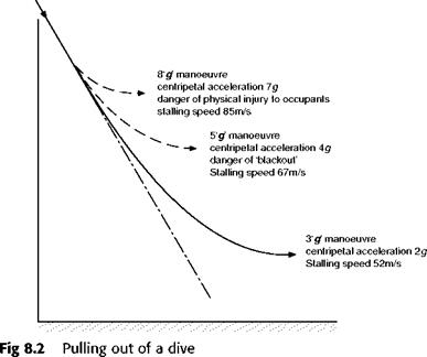
the aircraft stalling. The greater the centripetal acceleration required, the higher will be the stalling speed. Stalling whilst attempting to pull out too steeply is a condition that pilots must avoid at all times. The consequences can be disastrous, as many dive-bomber pilots have found to their cost. Figure 8.2 illustrates the case of an aircraft, having a level flight stalling speed of 30 m/s, pulling out of a steep dive. The load factor or ‘g’ level, the stalling speed and the centripetal accelerations are given for various cases.

Apart from the loads on the airframe, any manoeuvre involving large cen­tripetal accelerations will have a physical effect on the pilot. The pilot’s head will feel heavy, and he will experience difficulty in moving his arms, which now feel several times heavier than normal. Even at 1.5 ‘g’s, writing becomes difficult. Worse than this, however, are the effects that the centripetal acceler­ation can have on his blood circulation. At around 4 to 5 ‘g’, his heart, which is a pressure pump, will start to have difficulty pumping blood to his head, and if this is too severe, everything will appear to turn grey at first, and then he will be in danger of ‘blacking out’ and losing consciousness.

Apart from the problem of stalling, this physiological factor also imposes a limit on the severity of the manoeuvre that can be performed. In fighter air­craft, several means have been employed to increase the amount of centripetal acceleration that can be tolerated. One simple approach is to have the pilot lying as near to horizontal as possible whilst still being able to see where he is going. Another involves the use of special ‘g’ suits which inflate at strategic points to temporarily restrict the flow of blood from the head. Ultimately, for extreme manoeuvres, the only way to overcome the limitations of human physiology is to remove the pilot and use an unmanned air vehicle (UAV), either remotely controlled, or even as an autonomous robot.

Accelerations

Now the accelerations of an aeroplane along its line of flight are comparatively unimportant. They are probably greatest during the take-off, or, in the nega­tive sense, during the pull-up after landing. But the accelerations due to change in direction of flight are of tremendous importance.

Accelerations

Fig8A Manoeuvres

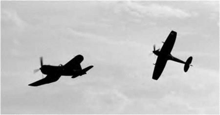
A clipped-wing Spitfire in mock combat manoeuvres with a Chance Vought Corsair.

As we have already discovered, when a body is compelled to move on a curved path, it is necessary to supply a force towards the centre, this force being directly proportional to the acceleration required. Such a force is called the centripetal force. The body will cause a reaction, that is to say an outward force, on whatever makes it travel on a curved path. This reaction is called by some people the centrifugal force.

If an aeroplane is travelling at a velocity of У metres per second on the cir­cumference of a circle of radius r metres, then the acceleration towards the centre of the circle is Y/r metres per second per second.

Therefore the centripetal (or centrifugal) force is m X acceleration, where m is the mass of the aeroplane in kilograms,

= mY/r newtons

In practice aeroplanes very rarely travel for any length of time on the arc of a circle; but that does not alter the principle, since any small arc of a curve is, for all practical purposes, an arc of some circle with some radius, so all it means is that the centre and the radius of the circle keep changing as the aero­plane manoeuvres.

The acceleration being Y/r shows that the two factors which decide the acceleration, and therefore the necessary force, are velocity and radius, the vel­ocity being squared having the greatest effect. Thus curves at high speed, tight turns at small radius, need large forces towards the centre of the curve.

We can easily work out the acceleration, Y/r. For instance, for an aeroplane travelling at 82m/s on a radius of 200 metres, the acceleration is (82 X 82)/200 = 34m/s2, which is a little less than 4 X the acceleration due to gravity. For convenience, this is often written as 4g. However, before we go any further, we need to try to clear up some misunderstanding about the use of the symbol g. This letter is unfortunately used to represent several different things. Firstly, it represents the gravitational constant. By multiplying the mass by the gravitational constant g, we obtain the weight (written in mathematical terms W=m g). The gravitational constant g has a value of 9.81 m/s2 on the earth’s surface, and this makes it look like an acceleration. In this context it is not an acceleration. As we noted in Chapter 1, a book resting on a fixed table has no acceleration, but it does have a weight equal to m X g newtons. The trouble is that g is also used to represent the acceleration due to gravity. If the book falls off the table, it will accelerate at 9.81 m/s2; the acceleration will then be equal to g (9.81 m/s2). Fortunately, although g is commonly used to repre­sent two different things, it always has a value of 9.81 m/s2, so we can still use it for both purposes, as long as we make quite clear whether we are talking about an acceleration or a weight. Finally, to make things even more con­fusing, pilots (and racing car drivers) often talk about pulling a certain number of ‘g’s. Unfortunately, this usage is so common that we cannot ignore it. This quantity is not an acceleration, it is just a number. It has no units, and it simply represents a factor which, when multiplied by the weight, gives the total force that must be applied to a body to balance the combined effects of gravity and centripetal acceleration. It is really a load factor, because it tells us how the loads and stresses in the airframe increase during a manoeuvre. In this book we will try to make things easier by using a bold letter ‘g’ in inverted commas for this quantity.

Let us try to show how the difference in usage works, by taking a simple example of an aircraft with a mass of 1000 kg, which therefore has a weight of lOOOg newtons, (since W=m g). We will take as an example, the case of this aircraft pulling out of a dive, where it is subjected to a centripetal acceleration of 3g at the bottom of the manoeuvre. The centripetal force required to provide this acceleration will be 1000 X 3g newtons (since force = mass X acceleration). Now 1000 X 3g newtons is a force equal to 3 times the weight. This centripetal force will be provided by the lift from the wings. However, the wing has to support the weight of the aircraft (1000 X g newtons) as well as providing the centripetal acceleration, so the total lift force must be 1000 X (3g +lg) newtons, which is 4 X the weight. The pilot therefore refers to this as a 4 ‘g’ manoeuvre. Not only will the lift and the stresses on the airframe by 4 times their normal level flight value, but the pilot will feel as though he weighs 4 times as much as usual. From the above, you can begin to appreciate the problem. A 4 ‘g’ pullout involves a 3g centripetal acceleration!

Now consider what happens if the aircraft is at the top of a loop at the same speed, and with the same radius of curvature. At the top of the loop, the cen­tripetal acceleration required will still be 3g, and the total force required to produce this will still be 1000 X 3g newtons. However the weight of the air­craft will provide part the centripetal force required (1000 X g newtons), leaving the wing lift (now pulling downward) to provide the extra 1000 X 2g newtons. Notice that although the centripetal acceleration is 3g, the wings only have to provide twice as much lift force as in level flight: that is 2 X the weight. Also, the pilot will not be squashed so firmly into his seat as at the bottom of the pull-out manoeuvre, as his weight is trying to pull him out of the seat. Because the lift required is only 2 X the weight, the load factor is only 2, and the pilot would call this a 2 ‘g’ manouevre.

If the loop were performed at the same speed, but with three times the radius, then the centripetal acceleration would be lg, so the required cen­tripetal force would be 1 X the weight, and the weight alone could provide all the centripetal force required. The wings would need to produce no lift at all. This is therefore called a zero ‘g’ manoeuvre. The pilot would temporarily feel weightless. Indeed, performing an outside loop or ‘bunt’, that is with the air­craft the right way up (see later in this chapter), with a lg centripetal acceleration is used as a way of providing trainee astronauts with an experi­ence of the weightless conditions that they will encounter in space flight.

Ceiling

This process of improving performance at altitude cannot be continued indefi­nitely and we shall eventually reach such a height that there is only one possible speed for level flight and the rate climb is nil. This is called the ceiling.

It requires extreme patience and time to reach such a ceiling, and, owing to the hopeless performance of the aeroplane when flying at this height, it is of little use for practical purposes, and therefore the idea of a service ceiling is introduced, this being defined as that height at which the rate of climb becomes less than 0.5 m/s, or some other specified rate.

Effect of weight on performance

It is sometimes important to be able to calculate what will be the effect on per­formance of increasing the total weight of an aeroplane by carrying extra load. Here again the performance curves will help us.

If the weight is increased, the lift will also have to be increased. So we must either fly at a larger angle of attack or, if we keep the same angle of attack, at a higher speed. This speed can easily be calculated thus –

Let old weight = W, new weight = Wv

Let У be the old speed, and Vj be the new speed at the same angle of attack. Since angle of attack is the same, CL will be the same.

.-. w = CL. ipV2 . s

and Wj = CL. ip Уj2 . S

so У/У = V(Wj/W)

Such problems always become more interesting if we consider actual figures; so suppose that we wish to carry an extra load of 10 000 N on our aeroplane which already weighs 50 000 N; then –

У/У = V(60 000/50 000) = Vl.2 = 1.095

Since the angle of attack is the same, the lift/drag ratio remains constant, and the corresponding drag, D, will be

D. = Db. = D X 65 000 = 1.2D 1 i 50 000

The corresponding power, P, is thus:

P1 = D1V1 = 1.2 X 1.095DL = 1.2P

So, for example, if we take the point on the power-required curve (Fig. 7.4) marked A, the corresponding point A, will be at

Vj = 1.095У, P1 = 1.2P

i. e. Vj = 1.095X 60 = 65.7m/s

and P1 = 1.2 X 310 = 372 kW

In a similar way, for each angle of attack, new speed and new power can be calculated, and thus a new curve of power required can be drawn for the new weight of the aeroplane.

It is interesting to note that the net effects of the additional weight are exactly the same as the effects of an increase of altitude, i. e. –

1. Slight reduction in maximum speed.

2. Large reduction in rate of climb.

3. Increase in minimum speed.

In short, the curve of power required is again displaced upwards. It will be noticed that there is too a slight increase in the best speed to use for climbing. (This must not be confused with rate of climb.)

In spite of the similarity in effect of increase of weight and increase of alti­tude it should be noted that the increase of weight does not affect the reading of the air speed indicator, and so the results apply equally well whether we consider true or indicated air speed.

The problems of operating piston engines at increasing altitude are such that their use is nowadays normally limited to flight at relatively low altitudes. This means that the piston engine is now relegated to use for light general avi­ation and specialist purposes. For propeller propulsion at higher altitudes and speeds, gas-turbine based turboprop propulsion is more appropriate, because the efficiency of the engine is less affected by altitude. The problem of pro­peller efficiency at high speed has been addressed with some success in recent years, and with very advanced propellers, it is indeed possible to fly even at transonic speeds. High-speed propellers are characterised by swept tips, giving a scimitar shape. The efficiency of propeller propulsion is theoretically greater than that of a pure jet, and for this reason, the turboprop is widely used for applications such as small regional airliners, transport aircraft and military trainers, where flight at very high altitude and speed is not necessary. Despite the advantages in terms of fuel consumption, the use of propellers does add to the weight, cost, complexity and servicing requirements.

Influence of jet propulsion on performance

In this chapter, we have so far looked at the performance of propeller driven aircraft, and it is now time to consider the effects of using turbojet propulsion. In Chapter 5 we saw that for the jet engine, thrust and fuel consumption do not change much with speed, and therefore the speeds for optimum range and endurance at any fixed altitude are faster than for a propeller driven aircraft with the same airframe. Also, as explained earlier in this chapter, by flying higher we will fly faster for a given amount of drag and thrust. This means that the optimum speeds for range and endurance also increase with altitude. Fortunately, the efficiency of the jet also rises with altitude, and we find that with turbojet propulsion, not only do the optimum speeds increase with height, but the number of kilometres that we can fly for each kilogram of fuel increases. Thus, for a jet aircraft, it is advantageous in terms of range, endurance and fuel cost to fly high and fast (Fig. 7C, overleaf). The limitation on maximum speed is normally provided by the onset of serious compress­ibility effects: transonic flow, which is dealt with in Chapter 11. The feature of obtaining the best economy at high speed is one reason for the popularity of jet propulsion for airliners, where passengers naturally want to get to their destinations as quickly and cheaply as possible. Other advantages are the low noise in the cabin, and the lack of vibration.

When considering the performance of jet aircraft, it is important to appreciate some important differences between the way that jet and piston – engined aircraft are controlled. On a piston-engined aircraft, the pilot controls the engine power by means of the throttle control, so called, because it tra­ditionally controlled the air flow into the engine by throttling it. On a jet aircraft, the pilot controls the engine by adjusting the fuel flow, and it is the thrust that is controlled directly, rather than the power. Despite the fact that this control does not actually throttle anything, it still tends to be called the throttle, for historic reasons.

Another difference between piston and jet propelled aircraft is that the higher speed of the latter means that the speed relative to the speed of sound becomes very important. For jet aircraft performance estimates, therefore, we need to display the data in a different form from that used for piston-engined aircraft. It is better to work in terms of thrust and drag rather than power required and power available, and we need to know how the thrust and drag vary with Mach number and altitude. This means that the simple performance calculations that we are able to use for practical purposes for low speed piston-engined aircraft are no longer appropriate for high-speed jet-engined aircraft. The proper method of dealing with their performance is rather com­plicated and beyond the intended level of this book, but in the numerical questions associated with this chapter, we have included some simple calcula­tions for jet aircraft at low speeds where compressibility effects can be ignored.

Ceiling

Can you answer these?

1. ‘When an aeroplane is climbing, the lift is less than the weight.’ Explain why this statement is not so inconsistent as it sounds.

2. What is the effect of altitude on the maximum and minimum speeds of an aeroplane?

3. Distinguish between ‘ceiling’ and ‘service ceiling’.

4. In attempting to climb to the ceiling, should the air speed be kept constant during the climb?

5. If the load carried by an aeroplane is increased, what will be the effects on performance?

For solutions see Appendix 5.

Numerical examples on Performance will be found in Appendix 3.

Fig 7C Cruise performance (opposite)

(By courtesy of the Boeing Company)

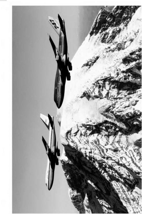
Two models of the Boeing 747. The nearer aircraft is a 747-400 which cruises at around 965 km/h (600 mph) at 9150 m, and has a cruise range of 13 528 km with 412 passengers.

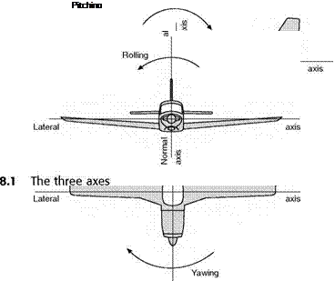
In a sense, any motion of an aeroplane may be considered as a manoeuvre. In no other form of transport is there such freedom of movement. An aeroplane may be said to have six degrees of freedom which are best described in relation to its three axes, defined as follows –

The longitudinal axis (Fig. 8.1) is a straight line running fore and aft through the centre of gravity and is horizontal when the aeroplane is in ‘rigging position’.

The aeroplane may travel backwards or forwards along this axis. Backward motion – such as a tail-slide – is one of the most rare of all manoeuvres, but forward movement along this axis is the most common of all, and is the main feature of straight and level flight.

Any rotary motion about this axis is called rolling.

The normal axis (Fig. 8.1) is a straight line through the centre of gravity, and is vertical when the aeroplane is in rigging position. It is therefore at right angles to the longitudinal axis as defined above.

The aeroplane may travel upwards or downwards along this axis, as in climbing or descending, but in fact such movement is not very common, the climb or descent being obtained chiefly by the inclination of the longitudinal axis to the horizontal, followed by a straightforward movement along that axis.

Rotary motion of the aeroplane about the normal axis is called yawing.

The lateral axis (Fig. 8.1) is a straight line through the centre of gravity at right angles to both the longitudinal and the normal axes. It is horizontal when the aeroplane is in rigging position and parallel to the line joining the wing tips.

The aeroplane may travel to right or left along the lateral axis; such motion is called sideslipping or skidding.

Rotary motion of the aeroplane about the lateral axis is called pitching.

These axes must be considered as moving with the aeroplane and always remaining fixed relative to the aeroplane, e. g. the lateral axis will remain par­allel to the line joining the wing tips in whatever attitude the aeroplane may

Ceiling

be, or, to take another example, during a vertical nose-dive the longitudinal axis will be vertical and the lateral and normal axes horizontal.

So the manoeuvres of an aeroplane are made up of one or more, or even of all the following –

1. Movement forwards or backwards.

2. Movement up or down.

3. Movement sideways, to right or left.

4. Rolling.

5. Yawing.

6. Pitching.

Some of these motions, or combinations of motion, are gentle in that they involve only a state of equilibrium. These have already been covered under the headings of level flight, gliding, climbing, and so on. In this chapter we shall deal with the more thrilling manoeuvres, those that involve changes of direction, or of speed, or of both – in other words, accelerations. In such manoeuvres the aeroplane is no longer in equilibrium. There is more thrill for the pilot; more interest, but more complication, in thinking out the problems on the ground (Fig 8A).

Effect of altitude on power curves

We have not yet exhausted the information which can be obtained from these performance curves, for if we can estimate the corresponding curves for various heights above sea-level we shall be able to see how performance is affected at different altitudes. There is much to be said, and much has been said, on the subject of whether it is preferable to fly high or to fly low when travelling from one place to another. It is one of those many interesting prob­lems about flight to which no direct answer can be given, chiefly because there
are so many conflicting considerations which have to be taken into account. Some of them, such as the question of temperature, wind and the quantity of oxygen in the air, have already been mentioned when dealing with the atmos­phere, but the most important problem is that of performance.

How will the performance be affected as the altitude of flight is increased? Well, as the altitude increases, the air density decreases. Therefore, to support the same aircraft weight whilst maintaining the same lift coefficient and atti­tude, it is necessary to increase the speed so as to maintain the same dynamic pressure. What this means is that we need to fly at the same indicated air speed. This also means that the drag will remain the same as before. Thus, from the point of view of the airframe, it appears at first as though there is no disadvantage in flying high. Indeed we can actually fly faster for the same amount of drag and thrust. The main trouble with flying high though comes from the engine and propulsion system. The propulsion problems may be sum­marised as follows.

1. The power required is the product of the speed and the drag, so although the drag and thrust can remain the same when the height is increased, the increase in the speed means that the power required will increase.

2. The power output of piston engines falls as the air density reduces, and although we can compensate for this by adding a supercharger or tur­bocharger, there is a limit to the amount of supercharging that it is practical to use.

3. Since we need to fly faster to maintain the same lift and drag, the propeller will also have to go faster, and we will run into problems associated with compressible flow over the propeller.

In addition to these propulsion problems there are some other important airframe and operational considerations.

4. The cockpit and cabin need to be pressurised, which adds to the com­plexity and weight.

5. As the height and speed are progressively increased, we will eventually encounter the problems associated with compressibility, especially in respect of the propeller.

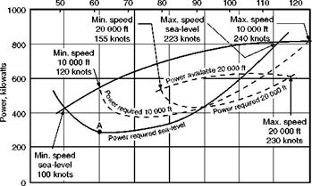
Whatever attempts are made to mitigate the difficulties of flight at high alti­tudes, in propeller-driven aircraft the general tendency remains for the power available to decrease and the power required to increase with the altitude (Fig. 7.4, overleaf). This will cause the curves to close in towards each other, resulting in a gradual increase in the minimum speed and a decrease in the maximum speed, while the distance between the curves, and therefore the rate of climb, will also become less. Any pilot will confirm that this is what actu­ally happens in practice, although, as previously mentioned, he may be

True speed of aeroplane, metres per second

Effect of altitude on power curves

80 100 120 140 160 180 200 220 240

True speed of aeroplane, knots

Fig 7.4 Effects of altitude

somewhat deceived by the fact that the air speed indicator is also affected by the change in density and consequently reads lower than the true air speed. This is really what accounts for the curve of power required moving over to the right as the altitude increases; if the curves were plotted against indicated speed, the curves for 3000 m and 6000 m would simply be displaced upwards, compared with that for sea-level. The difference between true and indicated speed also accounts for another apparent discrepancy in that the curves as plotted (against true speed) suggest that the air speed to give the best rate of climb increases with height. This is so, but the indicated speed for best rate of climb falls with height.

For certain purposes good performance at high altitudes may be of such importance that it becomes worth while to design the engine, propeller and aeroplane to give their best efficiencies at some specified height, such as 10 000 metres. It may then happen that performance at sea-level is inferior to that at the height for which the machine was designed. Even so, above a certain critical height, 6000, 9000 m or whatever it may be, performance will inevitably fall off and so the performance curves will be very similar, except that the highest curve of power available will correspond to the critical height. In such aircraft it may well be that the advantages of flying high outweigh the disadvantages.

Effect of changes of engine power

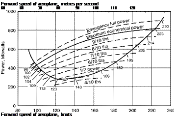
We have so far assumed that for a certain forward speed of the aeroplane the power available is a fixed quantity. This, of course, is not so, since the power of the engine can be varied considerably by manipulating the engine controls. If the curve shown in Fig. 7.2 represents the power available at some reason­ably economical conditions and in weak mixture, then we shall be able to get more power by using rich mixture, and the absolute maximum power by opening the throttle to the maximum permissible boost and using the maximum permissible rpm – with fixed-pitch propellers this will simply be a case of full throttle. From this we shall get a curve of emergency full power (Fig. 7.3, overleaf). It will be noticed that the minimum speed of level flight is now slightly lower – very slightly, so slightly as to be unimportant. The maximum speed is, as we might expect, higher – perhaps not so much higher as we might expect (118 instead of 115 m/s). The most important change is in the rate of climb: 460 kW surplus power is now available for climbing, and the rate of climb is 9.2 m/s instead of 7.2 m/s.

Except in special circumstances, it is inadvisable to fly with the engine ‘flat out’, and, even so, full power must be used only for a limited time or there will be a risk of damage to the engine. The effects of decreasing the power are also shown in Fig. 7.3. From the point of view of the aeroplane, it makes no difference whether the power is decreased by reducing boost, or lowering the rpm, or both; but for fuel economy it is generally advisable to lower the rpm. It will be noticed that as the power is reduced, the minimum speed of level flight becomes slightly greater, the maximum speed becomes considerably less, and the possible rate of climb decreases at all speeds.

Подпись: Forward speed of aeroplane, metres per second 50 60 70 80 90 100 110 120 Forward speed of aeroplane, knots

Fig 7.3 Effects of engine power

All this is what we might expect, with the possible exception of the fact, which pilots often do not realise, that the lowest speeds can be obtained with the engine running at full throttle. However, this flight condition cannot easily be sustained in practice because a small, inadvertent, decrease in speed would mean an increase in required power and a simultaneous decrease in available power. The speed reduction would then ‘run away’; a condition called speed instability.

Eventually, as the engine is throttled down, we reach a state of affairs at which there is only one possible speed of flight. This is the speed at which least engine power will be used, and at which we shall therefore obtain maximum endurance. It is rather puzzling to find that this speed (72 m/s) is different from the speed (64 m/s) at the lowest point of the power required curve. This is because the engine and propeller efficiency is slightly better at 72 than at 64 m/s.

Maximum and minimum speeds of horizontal flight

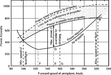
From the combination of the two curves (Fig. 7.2) some interesting deductions can be made. Wherever the power available curve is above the power required curve, level flight is possible, whereas both to the left and right of the two intersections it becomes impossible for the rather obvious reason that we would require more power than we have available! Therefore the intersection A shows the least possible speed (51 m/s, as we had discovered before for other reasons), and the intersection В the greatest possible speed (115 m/s), at which level flight can be maintained. Between the points A and В the difference between the power available and the power required at any particular speed,

i. e. the distance between the two curves, represents the amount of extra power which can be used for climbing purposes at that speed, and where the distance between the two curves is greatest, i. e. at CD, the rate of climb will be a maximum, while the corresponding point E shows that the best speed for climbing is 77 m/s. From the weight of the aeroplane 50 kN, and the extra power CD (680-320, i. e. 360 kW) available for climbing, we can deduce the vertical rate of climb, for if this is xm/s, then the work done per second in lifting 50 kN is 50 000 x watts,

So 50 000 x = 360 000

and x = 360 000/50 000 = 7.2 m/s

This represents the best rate of climb for this particular aeroplane, but it will only be attained if the pilot maintains the right speed of 77 m/s. As in gliding, there is a natural tendency to try to get a better climb by holding the nose up higher but, as will be seen from the curves, if the speed is reduced to 62 m/s only about 250 kN will be available for climbing, and this will reduce the rate of climb to 250 000/50 000, i. e. 5 m/s. Similarly, at speeds above 77 m/s the rate of climb will decrease, although it will be noticed that between certain speeds the curves run roughly parallel to each other and there is very little change in the rate of climb between 72 and 88 m/s; obviously at 51 m/s and again at 115 m/s, the rate of climb is reduced to nil, while below 51 and above 115 m/s the aeroplane will lose height.

As a matter of interest, the speeds for maximum endurance (F), 64 m/s, and maximum range (G), 82m/s, have also been marked. As was explained in Chapter 5, these are the best speeds from the point of view of the aeroplane, but they may have to be modified to suit engine conditions. Note that the speed for maximum endurance (F) could be deduced from the curve, since it is the lowest point on the curve, i. e. the point of minimum power required for level flight. The speed for maximum range (G), however, must be obtained from Table 5.2, which showed the drag at various speeds.

Power curves – propeller propulsion

An interesting and more practical way of approaching the climbing problem is by means of what are called performance curves. By estimating the power available from the engine and the power required for level flight at various speeds, we can arrive at many interesting deductions. It is largely by this method that forecasts are made of the probable performance of an aeroplane, and it is remarkable how accurate these forecasts usually prove to be.

The procedure for jet and rocket systems of propulsion is rather different because, as already mentioned, we must think in terms of thrust rather than power. They will therefore be dealt with separately, and the following dis­cussion relates primarily to piston-engined aircraft.

The deduction of the curve which gives the power output of the engine is outside the scope of this book, as it depends on a knowledge of the character­istics of the piston (or gas turbine) engine for a propeller-driven aircraft. From this curve must be subtracted the power which is lost through the inefficiency of the propeller (the efficiency of a good propeller at reasonable speed, but falling off on both sides depending on rpm, is about 80 per cent). The resulting curve (Fig. 7.2) shows the power which is available at various forward speeds of the aeroplane.

The power which will be required is found by estimating the drag. For this purpose the wing drag and the parasite drag are usually found separately, the former from the characteristics of the aerofoils and the latter by estimating the drag of all the various parts and summing them up. Another method of finding the total drag is by measuring the drag of a complete model in a wind tunnel and scaling up to full size. After the total drag has been found at any speed, the power is obtained by multiplying the drag by the speed, as in flying for endurance in Chapter 5, e. g. if the total drag is 4170 N at 82.4 m/s –

Power required = 4170 X 82.4 = 344 kW

And in a similar way the power required is found at other speeds, the lower curve in Fig. 7.2 illustrating a typical result. The reader may be puzzled as to

Forward speed of aeroplane, metres per second

50 60 70 80 90 100 110 120

Power curves - propeller propulsion

Fig 7.2 Power available and power required why the power required increases so rapidly at low speeds; the explanation is that in order to maintain level flights at these low speeds, a very large angle of attack is required, and this results in an increase of drag in spite of the reduc­tion in speed. If the argument sounds familiar, it is simply because we are returning to the same argument as when discussing range and endurance. The figures we have just quoted are taken from that argument, and the curve of power required in Fig. 7.2 is based on the aeroplane of Chapter 5. This follow­up of the same aeroplane will make the power curves more interesting and instructive.

It should be noted that there will be no fundamental difference in the shape of the power required curve for jet and propeller-driven aircraft. It is in the power available that the difference lies.

Climbing

During level flight the power of the engine must produce, via the propeller, jet or rocket, a thrust equal to the drag of the aeroplane at that particular speed of flight. If now the engine has some reserve of power in hand, and if the throttle is further opened, either –

(a) The pilot can put the nose down slightly, and maintain level flight at an increased speed and decreased angle of attack, or

(b) The aeroplane will commence to climb (Fig. 7B).

A consideration of the forces which act upon an aeroplane during a climb is interesting, but slightly more complicated than the other cases which we have considered.

Climbing

Fig 7B Climbing

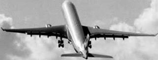
An Airbus A-330 using flaps to demonstrate its steep climb capability.

Climbing

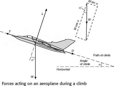
Assuming that the path actually travelled by the aeroplane is in the same direction as the thrust, then the forces will be as shown in Fig. 7.1. If a is the angle of climb, and if we resolve the forces parallel and at right angles to the direction of flight, we obtain two equations –

(1) T = D + W sin a (2) L = W cos a

Translated into non-mathematical language, the first of these equations tells us that during a climb the thrust needed is greater than the drag and increases with the steepness of the climb. This is what we would expect. If a vertical climb were possible, a would be 90° and therefore sin a would be 1, so the first equation would become T = D + W, which is obviously true because in such an extreme case the thrust would have the opposition of both the weight and the drag. Similarly if a = 0° (i. e. if there is no climb), sin a = 0. Therefore W sin a = 0. Therefore T = D, the condition which we have already established for straight and level flight.

Performance

It may seem rather illogical that we should first consider level flight, then gliding and landing, and now the take-off, climb and general performance of the aero­plane. But there is method in our madness. Tevel flight is, as it were, the standard condition of flight with which all other manoeuvres are compared. Gliding, too, involves simple fundamental principles, in some ways more elementary than those of level flight, handing we have used to illustrate the principles of flight at

low speeds. All these have followed quite naturally one take-off is a problem on its own.

on the other, but the

Taking-off

The pilot needs skill and practice before he can be sure of making a good take­off, one of the main problems being to keep the aircraft on a straight and narrow path. This difficulty applies mainly to propeller-driven aircraft, and has already been discussed in Chapter 4. In general, it may be said that the object during the take-off is to obtain sufficient lift to support the weight with the least possible run along the ground. In order to obtain this result the angle of attack is kept small during the first part of the run so as to reduce the drag; then, when the speed has reached the minimum speed of flight, if the tail is lowered and the wings brought to about 15° angle of attack, the aeroplane will be capable of flight. Although by this method the aeroplane probably leaves the ground with the least possible run, it is apt to be dangerous because, once having left the ground, any attempt to climb by further increase of angle will result in stalling and dropping back on to the ground. Therefore it is necessary to allow the speed to increase beyond the stalling speed before ‘pulling-off’, and sometimes the aeroplane is allowed to continue to run in the tail-up position until it takes off of its own accord (Fig. 7A, overleaf).

The process of taking-off is largely influenced by such things as the runway surface, and although of extreme interest, the subject is too complex to be

Performance

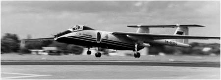
Fig 7 A Taking-off

The Myasischev M-55 high-altitude aircraft for surveillance and geophysics research.

within the scope of this book. In order to reduce the length of run, and increase the angle of climb after leaving the ground – so as to clear obstacles on the outskirts of the airfield – the take-off will, when possible, be made against the wind. Other aids to taking-off are slots, flaps or any other devices which increase the lift without unduly increasing the drag, and, essential in propeller-driven high-speed aircraft, the variable-pitch propeller.

The question as to whether or not flaps should be used for taking-off depends upon whether the increased lift of the flap, with the resulting decrease in taking-off speed, makes up for the lower acceleration caused by the increased drag of the flap. But the problem is a little more complicated than that, because while we wish to avoid drag throughout all the take-off run, we only really need the extra lift at the end, when we are ready to take off. No doubt we could get off most quickly by a sudden application of flap at this stage, but such a method would certainly be dangerous. The lift type of flap helps the take-off considerably, other types may have some beneficial effect if used at a moderate angle, and in practice some degree of flap is nearly always used for take-off in modern high-speed types of aircraft if only because it reduces the otherwise very high take-off speed with consequent wear of tyres.

Some interesting problems arise in connection with the take-off. Modern undercarriages may tuck away nicely during flight, but when lowered they are less streamlined than a fixed undercarriage and their drag may hamper the take-off quite considerably; the lower undercarriage that can be used with jets is a great advantage in this respect. Again, just as landing speeds go up with high wing loading, so do take-off speeds, and the length of run needed to attain such speeds is liable to become excessive. The idea of catapulting is an old one but its use has mostly been restricted to carrier-borne aircraft. The assistance of rockets gives much the same effect as catapulting, but has rarely been used. Refuelling in the air does not sound like a form of assisted take-off, but it does present possibilities in that an aircraft can be taken off lightly loaded as regards fuel.

Finally, although we have considered STOL and VTOL in their effect on landing, we must not forget that they are at least as important for take-off.