Effect of flaps on trim
The lowering or raising of flaps affects the airflow not only over the lower surface of the wing, but also over the upper surface – probably the more important effect – and in front of the wing and behind the wing (Fig. 6.10). The airflow in turn affects the pressure distribution and the forces and moments on the wing and on the tail plane. It is hardly surprising, therefore, that the trim may be affected, but it may seem curious that the lowering of the flap sometimes tends towards nose-heaviness, sometimes tail-heaviness.
Consider the top surface of the wing. When the flap is lowered, the air flows faster over the top, especially near the leading edge. There will be greater suction here and the chances are that the centre of pressure on the top surface will move forward, thus tending towards tail-heaviness.
The downwash behind the wing will be large; and if the tail plane is so situated as to receive the full benefit of this downwash, there will be a downward force on the tail plane, tending towards tail-heaviness.
In a low-wing aircraft the low position of the drag on the flap, especially when fully lowered, will tend towards nose-heaviness. On a high wing aircraft the drag, being high, may tend towards tail-heaviness.
The net effect on the pitching moment depends entirely on the type of flap or slots used, on how much they are lowered, and on the situation of the tail plane. Slotted flaps, and flaps that move backwards so increasing the rear portion of the wing area, will nearly always cause a nose-down moment which sometimes has to be counteracted by leading edge slots and flaps.
Sometimes, too, the change of trim is in one direction for the first part of the lowering of the flap, usually tail-heavy; and in the other direction, nose – heavy, when full flap is lowered. In some aircraft the effects, whether by design or good luck, so cancel each other that there is little or no change of trim, and no one is more pleased than the pilot.
It should be noted that the technique of landing a modern high performance aircraft, be it military or civilian, is nothing like the straightforward seat-of-
|
|
|
|
the-pants procedure described earlier for the case of a light private aircraft. For such modern aircraft, the speed, height, angle of descent and a host of other factors such as the flap and power setting must be correct within very close limits as the aircraft crosses the airfield threshold. If not, the pilot must abort the approach and try again. Landing a modern airliner manually requires a great deal of skill and concentration, and the majority of landings are nowadays made under automatic control with the pilot merely keeping a watchful eye, and being ready to take over at any instant in the event of a system malfunction. In order to maintain their skill (and their licence) pilots are, however, required to make a certain proportion of landings under manual control. It would be virtually impossible to land machines such as the Space Shuttle without some form of computer assistance.
Can you answer these?
1. If, when an aeroplane is gliding at its minimum angle of glide, the pilot attempts to glide farther by holding the nose of the aeroplane up, what will be the result, and why?
2. Discuss the effect of flaps on the gliding angle.
3. How does the load carried in an aeroplane affect the gliding angle and gliding speed?
4. Does the flattest glide give the longest time in the air? If not, why not?
5. Does (a) the stalling speed, (b) the stalling angle, change with height?
6. What are the advantages of the engine-assisted approach?
7. Why may the lowering of flaps affect the trim of an aeroplane?
8. You are flying an aeroplane well out to sea when the engine fails; there is a good airfield just on the coast and it is touch and go whether you can reach it; you have disposable load on board, luggage, bombs, and fuel; should you jettison your load, and if so when, and what should be your tactics in an endeavour to reach the airfield? (Note. There is more in this question than one might at first think, e. g. your tactics should be different for different wind conditions, so consider conditions of no wind, head winds, and tail winds; if you have surplus speed, what can you do with it?; can you reduce your drag?; should you use flaps?; at what speed should you fly?; should you jettison your load and, if so, when?)
For solutions see Appendix 5.
Numerical examples on gliding and landing will be found in Appendix 3.
The complete approach and landingDuring the few years preceding the Second World War, a new technique in flying was developed. In this book we are not concerned with the art of flying as such, but we are very much concerned with the alteration of technique because it was brought about by progress in the science of flight accompanied by the corresponding changes in aeroplane design. To the outward eye the main change was that the monoplane, rather suddenly, took precedence over the biplane. Less obvious, perhaps but more important, was the increase in wing loadings – which incidentally was itself the reason behind the ascendancy of the monoplane. With increase in wing loading came higher landing speed,
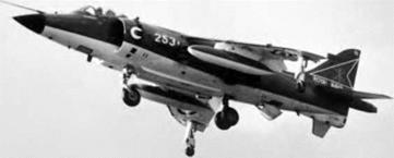
Fig 6G V/STOL The Harrier is capable of vertical take-off, very short take-off, and conventional take-off using its vectored-thrust Pegasus turbofan engine; it can also hover and fly sideways or backwards. Control at low speed is by reaction jet nozzles situated at the wing-tips and either end of the fuselage. (Photo courtesy of Nigel Cogger)
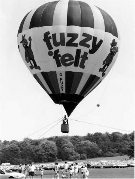
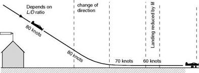
Fig 6H VTOL – another way After a century of neglect, the hot-air balloon has made a major comeback. This one is tethered and is being used for pilot training. The wicker basket provides good impact absorption on landing. higher landing speed meant that flaps – once a luxury – became a necessity, and flaps, in their turn, were largely responsible for the new technique, especially in so far as it affects the approach and landing. A pilot, when approaching a landing ground, may find that he is either undershooting or overshooting. If he is undershooting there is little that he can do (assuming, of course, that he is already gliding at the best angle) except use his engine power to flatten his glide. In the old days such a method was considered bad flying; if the engine was functioning satisfactorily, it showed lack of judgment; if the engine was out of action – that is to say in the case of a forced landing – it could not be done. Nowadays the engine-assisted approach, as it is called, is a standard method of approaching to land. It might almost be said that on the most modern machines the glide approach is only used as practice for a forced landing. In the anxiety to avoid undershooting there is a natural tendency to overshoot, especially since it would seem to be easy to lose any unnecessary height. In practice it is not quite so easy. In older types of aircraft the following methods were available as means of losing height in the event of overshooting – (a) Sideslipping. (b) Prolonging the glide by S-turns. (c) Putting the nose down and gliding fast. (d) Holding the nose up and gliding slowly. The objections to the last two have already been explained; the first two methods, on the other hand, were successfully employed for very many years. Then came the modern type of aircraft – its superior streamlining gave it a very flat gliding angle, so flat that even a slight degree of overshooting caused it to float much too far before landing. But that was not all – it did not like sideslipping (reasons for this will be given later), and with its very flat angle of glide the S-turn did not result in sufficient loss of height. Necessity may be the mother of invention, but in this little bit of aviation history the invention existed before the necessity arose; flaps had been in use for many years, but they had not really been fully applied to their modern purposes. These purposes can best be described by considering the process of approaching and landing a light private aircraft by the old-fashioned glide approach technique. This typically consists of five separate phases (Fig. 6.9) – the glide, the flattening-out, the float or hold-off, the landing, and the pull-up. In each and all of these flaps have their part to play. Tet us consider them in turn. First, then, let it be understood that the last 150 m or so of the glide should be straight, without any slipping or turning to one side or the other. This can only be done if the pilot has means of controlling the gliding angle relative to the earth without unduly raising or lowering the air speed. Flaps can give him So much then for the actual glide – we can sum it up by saying that flaps give us at least some control over the gliding angle (Fig. 61, overleaf). Next comes the process of flattening out; this involves a change of direction, and so an acceleration, and force, towards the centre of the curved path. This force must be provided by the wings which must therefore have more speed and more angle, so in effect the stalling speed is higher. Now the steeper the original glide, the greater the change in flight path involved, and so the more speed must there be in hand for flattening out. All this is very annoying – it means that the more steeply we glide, the faster must we glide; just what we were trying to avoid. The solution is to use engine power, as we shall consider later. After flattening out, we must lose any excess speed – this may be called the float or hold-off. In this the drag of flaps or air brakes play their part, as do the wings themselves as they are brought to the angle for actual landing.
After the float comes the landing (Fig. 6J, overleaf). This, in a sense, is momentary only but the landing speed is of the utmost importance because it settles both the gliding speed and the distance to pull up after landing. The problem of landing speed has already been fully discussed, but it must be emphasised – Fig 6.9 The approach and landing Air speeds shown are approximate only, but indicate at what parts of the approach and landing there is a loss of air speed.
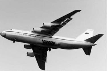
Fig 61 Ready for landing The huge Antonov AN-124 with Fowler flaps and leading edge slats extended, and undercarriage lowered, showing the ten pairs of main wheels. because it is so often misunderstood – that drag, whether caused by flaps or anything else, cannot reduce landing speed; that is entirely a question of lift. After the landing, the pull-up. This at least is easy to understand; what we need for a quick pull-up is drag – wheel brakes and air brakes – the more the better, provided the aircraft can stand it and does not tip on its nose. In addition to actual air brakes, some types of flap, when fully lowered, give good braking effect, and so do the wings at their angle of 16° or so with a tail-wheel type of undercarriage. The lack of air drag during the landing run is one of the few disadvantages of the nose-wheel type – an effective substitute, sometimes used, is a tail parachute (Fig. 6K, overleaf), and, perhaps most effective of all, reversible pitch propellers or reversed thrusts of jets. The air-braking effect is greatest at the beginning of the landing run, the wheel-braking later when it can more safely be used. The problem of brakes is a straightforward one of mechanics, but apart from the question of coefficient of friction between wheels and ground, and the serious danger of ‘aquaplaning’ when there is water on the runway, there are some aspects of brakes which are peculiar to aircraft. For instance, the centre of gravity is high above the wheels, though not so much with jets as with propellers; it is also, with a tail-wheel type of undercarriage, only a short distance behind the wheels, and so, if the brakes are applied violently there is an immediate tendency to go over on to the nose. Another difficulty is that if a tail-wheel aeroplane starts to swing, the centre of gravity, being behind the wheels, will cause the swing to increase. This may be checked by the differential action of the brakes, but it is interesting to note that the tricycle or nose-wheel undercarriage (Figs 6J, 6K and others) can remove the cause of this and other troubles. When this type of undercarriage is used, as it is almost universally on modern aircraft, the centre of gravity is in front of the main wheels and there is no tendency to swing, and at the same time the aircraft is prevented from going on to its nose by the front wheel. The effect on braking, and consequent shorter pull-up has to be seen – or, better still, tried – to be believed. And there are other advantages too. So much for the glide approach and landing; for forced landings it is the only way. For approaching over high obstacles at the edge of an airfield it may also come in useful. In all other circumstances, with modern types of aircraft, the engine-assisted approach is better, so let us sum up the reasons as to why it is preferred – 1. By slight adjustments of the throttle the path of glide can be flattened or steepened at will. 2. The gliding path is flatter, so there is less change of path in flattening out, less acceleration, less extra lift required, less increase in stalling speed, and thus less excess speed is needed, and the glide can safely be made more slowly. 3. In propeller-driven aircraft the extra speed of the slipstream over elevators and rudder makes these controls more effective – their effectiveness enables us to counteract wind gradient and turbulence effects near the ground. 4. Since there is less excess speed to be lost, the float is reduced.
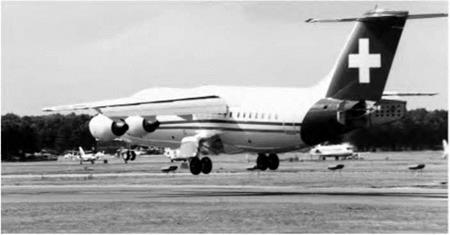
Fig 6) Landing A BAe 146 about to touch down, Fowler flaps extended and rear air-brake doors open.
Fig 6K Pulling up after landing Eurofighter Typhoon using an arrester parachute to reduce the landing run. 5. An engine, already running, will respond more readily to the throttle if it is found necessary to make another circuit before landing. 6. For all the reasons already given less judgment is required – the whole process is easier. Well, all that sounds pretty convincing, and not only is it perfectly sound reasoning but it is amply confirmed by experience. As was mentioned in Chapter 3 many modern types of aircraft are literally ‘flown onto the ground’ at speeds well above the stalling speed; this is where real lift dumpers come into their own – these are larger than normal air brakes or spoilers, and cannot be operated unless the undercarriage is locked down, and the aircraft is bearing on the wheels and the engines throttled back – they ‘kill’ the lift, keep the aircraft on the ground and make the wheel brakes more effective. They are essentially for use after landing, and are a common feature on gliders. Surface skimming vehiclesThe hovercraft can reasonably be counted as a type of aeroplane, as it does fly, albeit just above the ground. The hovercraft is lifted above the ground or water surface by means of a fan, which produces a raised pressure under the vehicle. Leakage of the air from the underside is restricted by a peripheral
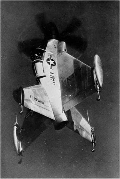
Fig 6E VTOL (By courtesy of the General Dynamics Corporation, USA) Pogo aircraft built for US Navy; after vertical take-off it could level off and fly horizontally; for landing the pilot pointed the nose straight up, and backed down tail first onto small wheels at trailing edges of wings and fins.
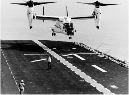
Fig 6F Convertiplane (By courtesy of Bell Helicopter Textron) The Boeing-Bell V-22 Osprey. Capable of VTOL and VSTOL. The engines can be rotated to provide conventional forward flight after take-off. ‘curtain’ of high speed air, normally supplemented by a flexible ‘skirt’. At one time, the hovercraft was seen as a major new type of transport vehicle, and for many years hovercraft operated a ferry service across the English Channel. In fine weather this provided a much faster alternative to the conventional ferries. However, the hovercraft were expensive to run and maintain. Also they could not be operated in very heavy seas, and were prone to generate nausea amongst the passengers even in moderate seas. Nowadays hovercraft are mostly used for very specialised operations, for example in swampy areas, and for recreational and competition use. For ferry duties, they have been largely superseded by various types of catamaran and hydrofoil. Another type of vehicle that flies just above the surface is the surface skimmer or ekranoplane. These aircraft resemble a conventional aircraft, but by flying just above the surface, take advantage of the ‘ground effect’ which greatly reduces the wing downwash, and consequently reduces the accompanying trailing vortex drag. Some extremely large and very fast aircraft of this type were under development in the old Soviet Union just before its collapse, but subsequent economic difficulties brought further development to a virtual standstill. The main disadvantages of the ekranoplane are the problems of ensuring the correct ground clearance at all times, and the very large amount of engine power needed to get the aircraft to lift off from the water. Several large turbojets were needed on the larger experimental aircraft, and once liftoff had been achieved, most of them became redundant for the rest of the journey. Other short and vertical take-off aircraftAs with high-lift devices, there have been very many ideas for vertical or short take-off aircraft. Ignoring the untried or less promising examples, we are left with three main approaches to the problem. These are – (a) Tilting the whole aircraft, as shown in Fig. 6E (overleaf). A small number of successful experimental aircraft were built, but the practical problems (such as seeing where you are going on landing) remained too daunting for further development. (b) Tilting the engines and wings for take-off and landing, whilst leaving the main body of the aircraft horizontal. Several experimental aircraft have been flown, but no production types have been forthcoming. (c) Tilting the rotors/propellers or the engines and rotors/propellers. Again, many experimental aircraft of this type have been flown, but it was only after much political indecision and a number of serious technical set-backs that the go-ahead was finally given for series production of the Boeing-Bell V 22 Osprey tilt-rotor aircraft (Fig. 6F, overleaf). This aircraft combines the features of conventional aircraft and helicopters. In high speed flight, the rotors are tilted forward and become large diameter propellers, so the aircraft does not suffer the same speed limitations as a conventional helicopter. The cost and complexity are however high. Another aircraft using this principle is the smaller Bell/Augusta BA609. The helicopterIn a true helicopter in normal flight, the upward thrust of the revolving blades must be equal to the weight; forward motion is produced by inclining the effective axis of the rotor forward which normally entails tilting the nose of the helicopter down. The actual means by which this is achieved is rather complicated and involves altering the cyclic variations in rotor blade incidence. Owing to the reaction of the torque of the lifting blades the whole aircraft will try to rotate in the opposite direction, this resulting in a tendency to yaw which corresponds to the rolling tendency due to the propeller on a fixed-wing aircraft. The yawing tendency can be counteracted either by an auxiliary propeller or by a jet reaction system at the tail; this can also be used to provide directional control and to save the necessity of having a rudder (Fig. 6D). The development of successful helicopters has involved the solution of many other practical problems. The blade going into the wind (the wind produced by the motion of the aircraft) gets more lift, and drag, than the blade going down wind. This happens whenever the machine moves in any direction, forwards, backwards or sideways; but it becomes an even more serious problem when moving at high speeds because the tip portions of the blade going into the wind meet compressibility problems before the aircraft itself is moving anywhere near the speed of sound; this fact has so far limited the speed of helicopters to something like 200 knots (370km/h). The helicopter has other failings too, vibration is apt to be excessive, as is the noise when compared with aircraft of similar power. Attempts to solve these and other problems have resulted in wings that must not only rotate, but also have cyclically and collectively variable incidence, hinges to give variable dihedral (resulting in a kind of flapping motion of the blades), drag hinges to allow the blades to bend backwards, and sometimes, a tilting axes of rotation. Then there are the auxiliary propellers at the tail, or jets, some have had jets too at the wing tips to rotate the blades, some have had more than one set of rotating wings (like contra-rotating propellers), and there have been many other ingenious devices, all helping to some extent to solve the problems, but all contributing to the complication and weight of an already complicated type of aircraft. Recent developments have included the use of so-called ‘rigid’ rotors, where the flapping and drag hinges are replaced by flexures. This has reduced the mechanical complexity, and also the weight of the rotor head. Another development has been the shrouding of the tail rotor in a kind of fin. This results in less drag and reduces the possibility of accidental contact with the tail rotor. A further development has been the replacement of the tail rotor with a variable air jet at the rear to perform the same function. This type, known as a NOTAR, (standing for No Tail Rotor) is much quieter than the conventional helicopter, and also avoids the possibility of damage to or from the tail rotor. The main limitation of a conventional helicopter remains its low maximum speed. One of the reasons for this is that in order to generate lift, a significant
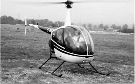
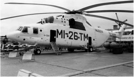
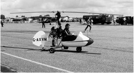
Fig 6D VTOL – helicopters Top: The tiny but popular Robinson R-22, with piston engine and rubber belt drive. Flying it feels like trying to ride a monocycle at first. Bottom: At the other extreme, the massive Russian Mil Mi-26 TM capable of lifting a load of 196 000 newtons (20 tonnes). part of the retreating blades must be going faster than the relative air speed past the helicopter. This means that the advancing ones will be going more than twice as fast as the aircraft, and will therefore go supersonic when the aircraft is still flying at significantly less that half the speed of sound. Several solutions have been proposed and even developed. One of these is the so-called ‘compound’ helicopter. This has the normal features of a conventional helicopter but also has small wings and a separate engine or engines to provide forward thrust directly. At high speed, the wings provide most of the lift, allowing the rotor to be rotated relatively slowly or even be feathered. A number of examples have been built, but so far it remains something of a rarity. A possible alternative is provided by development of the coaxial rotor helicopter which has two contra-rotating rotors mounted on the same shaft or sometimes two close shafts with intermeshing rotors. On this arrangement, it is possible to arrange for the lift to be generated primarily by the advancing blades of the rotors, the retreating blades providing little or no lift. Since they do not have to provide lift, the retreating blades can be feathered and do not need to go faster than the relative flow speed past the aircraft. This of course means that that the advancing blade can be going correspondingly slowly. Many practical examples of coaxial rotor helicopters have been manufactured and they are not uncommon, particularly in military applications. They have the added advantage that no tail rotor is required. Their disadvantage lies in the extreme complexity of the rotor head, and the problems caused by intersecting rotor wakes. As yet, the potential of the coaxial rotor for very high speed flight has not yet been realised on production examples. Jet lift Until recently, the only serious contenders to the helicopter have been jet lift and thrust vectoring aircraft, and the only really successful one was the Harrier, (known as the AV-8 in the USA). The Harrier (Fig. 6G, later) uses downward deflection of the engine to produce a lifting thrust until sufficient forward speed has been obtained for the wings to take over the job of lifting. The engine outlet nozzles, two from the hot exhaust and two from the compressor, can be ‘vectored’ (varied in outlet angle) from vertical or even slightly forward, to horizontal in order to obtain the desired balance between lift and forward thrust. The thorny problem of providing stability and control at low speed is solved by using four ‘puffer’ jets of compressed air bled from the engine. These are situated at the nose, the tail and both wing tips. Tike the helicopter, this aircraft can be flown backwards forwards and sideways. It can also hover and land and take off vertically. Although it is capable of vertical take-off, it is more economical in terms of fuel burn for the aircraft to make a short horizontal take-off, with the engines set at an intermediate angle so as to provide thrust and some lift. It may therefore be classified as V/STOT, meaning that it can use vertical and short take-off. During the cold war, the Soviet Union developed a rival to the Harrier, the Yakovlev Yak-36. This aircraft used an alternative method of jet lift in that it employed separate engines for lift instead of just relying on thrust vectoring. For many years, however, the Harrier was the only really practical jet lift aircraft in service anywhere, but after much political indecision and argument, the Lockheed Martin F-35 JSF (Joint Strike Fighter) finally emerged. Some variants of this have similar V/STOL capabilities to the Harrier, and a much higher top speed. Thrust vectoring is used, but in addition, a fan driven by the engine provides part of the lift. The gyroplanePerhaps the first really practical achievement in this direction was the Cierva Autogiro in 1923 The Autogiro was not a helicopter, but a gyroplane, and a gyroplane differs from a helicopter in one vital particular in that, whereas in a helicopter the wings or blades are rotated by the power of the main engine, in a gyroplane the rotating wings are not driven except by the action of the air upon them, and this in turn is caused by the forward or downward air speed of the aircraft. Thus forward speed is necessary in a gyroplane, just as it is in a conventional aeroplane and, as in the latter, it is provided by the thrust of an ordinary engine and propeller. A modern gyroplane is shown in Fig. 6C (top). Space does not permit a full consideration of the principles underlying this very interesting flying machine, and it must suffice to say that the secret lies in the fact that by a suitable inclination backwards of the axis the wings rotate automatically in such a way that even when the forward speed of the aircraft is far lower than the stalling speed of a conventional aeroplane the rotating wings are still striking the air at a considerable velocity, and can thus provide sufficient lift to keep the aircraft in the air. In this way the forward speed can be reduced to 5 or 10 knots which, in a slight head wind, means a ground speed of practically nil. When the Cierva Autogiro first appeared it succeeded in achieving, in one fell swoop, a landing speed such as the experimenters of all nations had considered to be a dream of the distant future. Moreover later developments resulted, in 1935, in a ‘jump start’, or true vertical take-off, achieved by rotating the wings on the ground (by engine power), and then suddenly increasing the pitch, or angle of attack of the blades. The gyroplane, sometimes called an autogyro (the spelling Autogiro was a trade name), still has its advocates, and still exists in various forms, including very light and simple single-seaters (Fig. 6C).
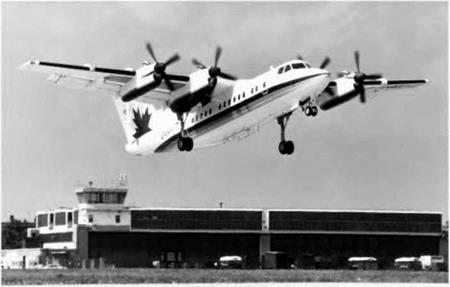
Fig 6C STOL Top: The autogyro after almost disappearing as an historical curiosity has made a comeback in the form of a popular ultralight. Bottom: The de Havilland Canada Dash-7, original mainstay of the London City (STOL) Airport. The four propellers provided a’ high-energy airflow over much of the wing. (Photo by courtesy of Terry Shwetz, de Havilland Canada.) Landing speeds and the futureSo far as landing speed is concerned, we are reaching an interesting stage in the history of aviation. Wing loadings are still going up; they went up slowly but surely for the first thirty years of flight, and rather less slowly, but more surely, during the Second World War – and since. There is at the moment no sign of any halt in this progress – for progress it certainly is. We must assume, therefore, that wing loadings will go still farther. During this time, slots and flaps, and then better flaps, have been invented, and the maximum value of CL has gone up from just over 1 to about 3, or even 4, for a good modern aerofoil section with slotted flaps and slots extending along 60 per cent of the wing span. When the maximum CL was 1.22 (RAF 15), a wing loading of 500 N/m2 was considered high; but with a CL max of 3, even 5000 N/m2 has already been exceeded. Now a CL max of 1.22 and W/S of 500 gives a landing speed of about 50 knots (93 km/h) whereas a CL max of 3 and W/S of 5000 gives a landing speed of about 102 knots (188 km/h). So we have accepted a considerably higher landing speed – but how long can this go on? The increase in wing loading has already had a greater effect than the increase in maximum lift coefficient, but so far we have discovered better and better flaps. Now, however, it would seem that there is not much hope of any further great improvement in flaps – so what of the future? The first thing we must do is clear enough – flaps, and slots too, must extend along the whole span of the wing, perhaps also under the fuselage; this has already been done in some types of aircraft, sometimes by arranging that the ailerons act also as flaps, therefore known as ‘flaperons’ or by dispensing with the ailerons altogether and adopting an alternative form of lateral control, such as spoilers – this will be discussed later, or by differential movement of the tail surfaces, thus known as ‘tailerons’. Such methods might give us another 40 per cent increase in maximum lift coefficient and a landing speed of about 86 knots (158 km/h) for a wing loading of 5000 N/m2. So what are the prospects for the future? Well, there has been no shortage of ideas, and the patent offices of the world contain hundreds of examples, ranging from the good to the impractical or ill-conceived. Amongst the good ideas is that of using high pressure air bled from the engine compressor to help induce attached flow over the flaps (blown flaps) at large deflections, or even to produce a downward curtain of air which can turn the main airflow through extremely large angles: the so-called jet flap. Such devices, though effective, are however complex and heavy, and have generally only been used for specialised aircraft, usually military. An example of an apparently promising idea that never went into general use is the Custer channel wing shown in Fig. 6.8. The idea was quite simple; the propellers drew air over the curved wing sections, thereby allowing the flow to remain attached at high angles of attack. However, there are two main problems with most of such ideas. Firstly the lifting surface also needs to have a good lift to drag ratio at high speed, and secondly, as the minimum speed of the aircraft decreases, it becomes more and more difficult to provide adequate stability and control by conventional means. Other approaches to providing lift at low or even zero speed are dealt with below.
Fig 6.8 The idea of the ‘Custer’ channel wing The engines – with pusher propellers – were suspended in the channels with the ailerons just outboard of the channels. Short and vertical landing and take-off The idea of low landing speeds or even vertical landing was a much sought – after goal even in the earliest days of flying. In fact, until the twentieth century, the only manned flights were made in vertical take-off devices: balloons and airships. Over the years, there has been considerable research into both vertical and short take-off aircraft, and one firm outcome has been the coining of two acronyms, VTOL for Vertical Take-off and handing, and STOL for Short Take-off and handing. To this has been added some hybrids like STOVL, Short Take-off and Vertical handing. In the following sections, some of the more successful or promising types are described. Method of finding minimum landing speedConsider this problem – Find the wing area required for an aeroplane of mass 1500 kg, if the minimum landing speed is to be 35 knots (65 km/h) and the maximum value of the lift coefficient for the aerofoil used is 1.2 (assume the air density to be 1.225 kg/m3). Data: W = 14 715 N p = 1.22= kg/m3 VL = 65 km/h = 18m/s CL max = 1.2 S = ? So 14 715 = 1.2 X – X 1.225 X 18 X 18 X S 2 c. S = 62 m2 approx This is rather a large wing area for an aeroplane of this weight, and it is doubtful whether the structure involved would not make the total weight greater than 14 715 N, in which case, of course, the landing speed would be above 35 knots. Suppose we could use a flapped wing with a maximum lift coefficient of 1.8 instead of 1.2, then, neglecting any small increase in weight, the necessary wing area to produce the same landing speed would be – (1.2/1.8) X 62 = 41 m2 approx It would certainly be much easier to design a wing structure of this size so as to conform to a total weight of 14 715 N and, further, the reduced wing area would enable a much greater maximum speed to be obtained. As another problem, let us compare the minimum landing speeds of the following – (a) A sailplane of wing loading 100 N/m2. (b) A training machine of wing loading 400 N/m2. (c) A fighter of wing loading 1500 N/m2. (d) The S.6b of wing loading about 2000 N/m2. (e) An airliner of wing loading 3000 N/m2. Supposing other things to be equal, e. g. taking p as 1.225 kg/m3, and assuming each machine is fitted with an aerofoil section having a maximum lift coefficient of 1.12, then – (a) Wing loading = W/S = 100 = CL max fpVL2 = 1.12 X I X 1.225 X VL2 У 2 = (100 X 2)/(1.12 X 1.225) = 146 .•. VL = 12 m/s, i. e. 23 knots or 43 km/h Similarly for (b) Landing speed = 47 knots (87km/h) (c) 91 knots (169 km/h) (d) 106 knots (195 km/h) (e) ? knots (? km/h). Reader, work it out. Such is the type of problem which confronts the designer of an aeroplane in the very early stages, when, by a process of calculations, he has to decide such important items as the wing area, the type of aerofoil, and the landing speed. It will now be obvious that in order to settle these he must know the weight – the weight of an aeroplane which he has not yet commenced to design! Here comes the first great guess; but it is a guess based on experience, and often proves remarkably accurate. A decision as to landing speed and as to the type of aerofoil will then decide the wing area, on which the whole lay-out of the aeroplane depends, so it will be seen how important is this question of landing speed and its influence on the whole design of the finished aeroplane. Wing loadingThe fraction W/S, weight divided by wing area, is called the wing loading of the aeroplane. An increase in the wing area should reduce the value of W/S, and so also reduce the minimum velocity at which level flight is possible. The objections to variable area are chiefly mechanical; the operating gear means extra weight and so, since W will increase, it by no means follows that W/S will actually decrease if the wing area is increased; also, once again, the extra sophistication means more complication, more levers for the pilot to fiddle with, more chances of something going wrong. Some flap systems do, however, give an increase in wing area during landing as they extend beyond the trailing edge of the wing. Apart from the question of altering the wing area during flight, the equation W/S = CL. 2pV2 shows us that, other things being equal, the aeroplane with a low wing loading will have a lower minimum speed than one with a high wing loading. The so-called ‘light aeroplane’ may have a high wing loading, and therefore a high landing speed; in other words, it is not a question of weight, but of weight compared with wing area, that settles the minimum speed. The wing loading of a sailplane may be less than 100 N/m2, of a training aeroplane 300 to 1000 N/m2, of a fighter, bomber or airliner anything from 1500 up to 2000, 3000 or more N/m2. The modern tendency is to increase wing loading by reducing wing area and thus raising the maximum speed, and then using flaps to keep down the landing speed. The student is advised to work out the wing loading of existing aeroplanes and to compare the figures obtained with their landing speeds; in making this comparison, however, the student must be careful to notice the above phrase ‘other things being equal’, because the maximum lift coefficient of the aerofoil used also affects the result. An old example of high wing loading, very high for that time, was the 1977 N/m2 of the S.6b Schneider Trophy racing seaplane; the corresponding figure for fighters like the ‘Spitfire’ and ‘Hurricane’ at the beginning of the Second World War was 1187 N/m2, and for the German fighter, Messerschmitt 109, 1522 N/m2. Modern figures may be considerably higher than these; the Concorde was about 4800 N/m2. High lift aerofoilsWhat, then, has been done, and what can yet be done to decrease minimum speed? If У is to be small, CL must be as large as possible. In other words, we must have a larger lift coefficient. So the aerofoils which give the largest maximum lift coefficient will give the lowest minimum speeds. Unfortunately, however, these aerofoils are usually those with a large drag, and so they seriously affect the high speed end of the range. Therefore we must turn to some device by which the shape of the aerofoil can be altered during flight, and so we naturally think of flaps and slots. In an earlier chapter (Fig. 3.32) we noticed the effect of various kinds of flaps and slots on maximum lift and speed range. The idea of variable camber is an old one, but it is only in recent years, when maximum speeds have increased so much, that the problem has become really urgent and these devices have come into their own. In this respect necessity has proved to be the mother of invention, and many and varied have been the devices which have been tried. It is not easy to compare the respective merits of all these types of slots and flaps, or combinations of slot and flap, because so many conflicting qualities are required. If a low speed was our only aim, the problem would be comparatively simple, the device giving the highest maximum lift coefficient being the most suitable. But what we really need is a low minimum speed and a high maximum speed, i. e. a good speed range. This condition means that the device must be such that it can be altered, or will alter automatically, from the position giving maximum lift (e. g. slot open or flap down), to the position of minimum drag (e. g. slot closed or flap neutral). Even that is not the end of our requirements for, having landed as slowly as possible, we must pull up quickly after landing. The former (slow landing) needs high lift, the latter (quick pull – up) needs much drag, lift being of no consequence at all. For a quick pull-up we really need a definite air brake which will assist the wheel brakes. Notice, however, that an air brake cannot reduce actual landing speed, it can only improve the pull-up after landing. Once we are on the ground we want to get rid of lift as quickly as possible to achieve minimum wheel brake effectiveness; hence the use of lift dumpers after touchdown. These are usually devices which disrupt the flow over the top of the wing, increasing drag, and decreasing lift. Yet another aspect of the problem, so far as landing is concerned, is the question of attitude, and in this respect some of the otherwise most effective types of slots and flaps are at a disadvantage, for they attain their maximum lift coefficient at a greater angle of attack than the ordinary aerofoil; this means that in order to make full use of them the angle of attack when landing may need to be 25°, or even more. But when an aeroplane with a tail-wheel type of undercarriage rests with its main and tail wheels on the ground, the angle of inclination of the wings is only about 15°. With a nose-wheel type of undercarriage the problem is if anything, worse – as the reader will no doubt realise – for, in order to land at an angle of 25°, we are faced with four possibilities all of which have serious drawbacks – [6] [7] [8] [9]
(d) Large riggers’ angle of incidence Fig 6.7 Difficulties of landing at large angles of attack maximum lift and still maintain a reasonable attitude for landing. Improvements in design on these lines have resulted in a real, and by no means negligible, reduction in landing speed (or perhaps, more correctly, has halted further increases in landing speed) but at the expense of ever more sophistication – and ever more complication. |


