Category MECHANICS. OF FLIGHT

Flying for range – jet propulsion

In trying to get maximum range or endurance out of any aircraft we are, in effect, simply trying to get maximum value for money, the value being the

range or endurance and the money being the fuel used. We shall only get the maximum overall efficiency if in turn we get the maximum efficiency at each stage of the conversion of the fuel into useful work done. The three main stages are the engine, the system of propulsion, and the aeroplane.

This applies to every type of aircraft – it is necessary to emphasise this point because there seems to be a growing tendency to think that jet or rocket propulsion involves completely new principles. This is not so – the principles are exactly the same, the only difference lies in the degree of importance of the various efficiencies.

From the point of view of an aeroplane, flying for maximum range means flying with minimum drag. It is in that condition that the aeroplane is most efficient no matter by what means it is driven. But if, when we fly with minimum drag, either the propulsive system, or the engine, or both, are hope­lessly inefficient – then, rather obviously, it will pay us to make some compromise, probably by flying rather faster than the minimum drag speed.

From the point of view of an aeroplane, as an aeroplane, we shall obtain the same range at whatever height we fly, provided we fly in the attitude of minimum drag. But if at some heights the propulsive system, or the engine, or both, are more efficient than at other heights – then, rather obviously, it will pay us to fly at those heights so as to get the maximum overall value out of the engine-propulsion-aeroplane system.

Now an aeroplane is an aeroplane whether it is driven by propeller or jet and, as an aeroplane, the same rules for range flying will apply. But when the efficiencies of the propulsion system and the engine are included the overall effects are rather different. In the propeller-driven aeroplane we do not go far wrong if we obey the aeroplane rules although, even so, it usually pays us to fly rather faster than the minimum drag speed because, by so doing, engine and propeller efficiency is improved – and flying is more comfortable. It also definitely pays us to fly at a certain height because at that height the engine – propeller combination is more efficient. But in the main it is the aeroplane efficiency that decides the issue. Not so with the jet aircraft.

There are two important reasons for the difference –

1. Whereas the thrust of a propeller falls off as forward speed increases, the thrust of a jet is nearly constant at all speeds (at the same rpm).

2. Whereas the fuel consumption in a reciprocating engine is approximately proportional to the power developed, the fuel consumption in jet propul­sion is approximately proportional to the thrust.

Both of these are really connected with the fact that the efficiency of the jet propulsion system increases with speed, and this increase in efficiency is so important that it is absolutely necessary to take it into account, as well as the efficiency of the aeroplane. When we do so we find that we shall get greater range if we fly a great deal faster than the minimum drag speed. The drag will

Table 5.4 Air speed and drag ratios

Air speed

Drag/Speed

Air speed

Drag/Speed

100

8330/100 = 83.3

220

6940/220 = 31.5

120

4720/120 = 39.3

240

8330/240 = 34.7

140

4240/140 = 30.3

260

9615/260 = 37.0

160

4170/160 = 26.1

280

11 110/280 = 39.7

180

4670/180 = 25.9

300

13 160/300 = 43.9

200

5880/200 = 29.4

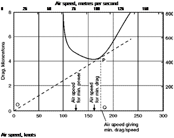
be slightly greater – not much, because we are on the low portion of the curve (Fig. 5.12) – the thrust, being equal to the drag, will also of course be slightly greater, and so will the fuel consumption in litres per hour. The speed, on the other hand, will be considerably greater and so we shall get more miles per hour. Everything, in fact, depends on getting the maximum of speed compared with thrust, or speed compared with drag. In short, we must fly at minimum drag/speed which as the figure shows, will always occur at a higher speed than that giving minimum drag (Fig. 5.12). So to get maximum range jet aircraft must fly faster than propeller-driven aircraft – the difference being due to the different relationship between efficiency and speed in the two systems.

As a matter of interest let us go back to the figures and work out for each speed the value of drag/speed (Table 5.4).

Since, in this instance, we are only concerned with the air speed at which minimum drag/speed occurs, there is no need to convert the knots to m/s.

Note that the minimum value for drag/speed is at about 175 knots, so the range speed for this aircraft, if driven by jets, is 175 instead of 160 knots; but, what is more important, note the shape of the drag/speed curve (Fig. 5.13, overleaf); whereas the other curves rise fairly steeply above the minimum value the drag/speed curve hardly rises at all between 170 and 280 knots, so with jet propulsion we can get good range anywhere between these speeds.

At what height shall we fly? That is an easy one to answer. We know that it makes no difference as far as the efficiency of the aeroplane is concerned – but it makes all the difference to the efficiency of jet propulsion. The aircraft will be in the same attitude, and we shall get the same drag and the same thrust, if we fly at the same indicated speed at altitude – but the true speed will be greater. Now it is the true speed that largely settles the overall efficiency so at 40 000 ft (12 200 m), where the true speed is doubled, the efficiency will be greatly increased, and, provided the fuel consumption remains proportional to thrust, the range will be similarly increased. So to get range on jet aircraft – fly high.

Since modern flights in jet aircraft may take place at heights such as 40 000 or 50 000 ft (12 200 m or 15 200 m) quite a large proportion of the flights may be spent in climbing and descending, and in order to obtain maximum range rather different speeds may be required say for climbing and for the level
Подпись: Air speed, metres per second 0 25 50 75 100 125 150 Air speed, knots

Fig 5.12 Flying for range: jet propulsion

The tangent OP to the curve of total drag gives the air speed Q at which drag/speed is a minimum.

portion of the flight. The best speed, for instance, for a cruising climb may be 1.3 X speed for minimum drag, and for level flight 1.2 X speed for minimum drag, i. e. for the aeroplane which we have considered, 208 and 192 knots respectively.

Range flying – effects of wind

If the flight is to be made from A towards В and back to A, then wind of any strength from any direction will adversely affect the radius of action. This fact, which at first sounds rather strange, but which is well known to all students of navigation, can easily be verified by working out a few simple examples, taking at first a head and tail wind, and then various cross-winds. But the wind usually changes in direction and increases in velocity with height, and so a skilful pilot can sometimes pick his height to best advantage and so gain more by getting the best, or the least bad, effect from the wind than he may lose by flying at a height that is slightly uneconomical from other points of view. It may pay him, too, to modify his air speed slightly according to the strength of the wind, but these are really problems of navigation rather than of the mechanics of flight.

Flying for endurance – propeller propulsion

We may sometimes want to stay in the air for the longest possible time on a given quantity of fuel. This is not the same consideration as flying for maximum range. To get maximum endurance, we must use the least possible fuel in a given time, that is to say, we must use minimum power. But, as already explained, power means drag X velocity, the velocity being true air speed. Tet us look back to Table 5.2 showing total drag against air speed; mul­tiply the drag by the air speed and see what happens.

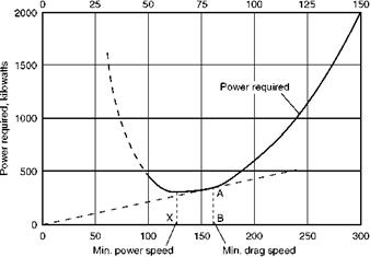
Table 5.2 shows that, although the drag is least at about 160 knots, the power is least at about 125 knots (see also Fig. 5.11, overleaf). The expla­nation is quite simple; by flying slightly slower, we gain more (from the power point of view) by the reduced speed than we lose by the increased drag. Therefore the speed for best endurance is less than the speed for best range and, since we are now concerned with true speed, the lower the height, the better.

The endurance speed is apt to be uncomfortably low for accurate flying; even the best range speed is not always easy and, as neither is very critical, the pilot is often recommended to fly at a somewhat higher speed.

The reader who would like to consider endurance flying a little further should look back to The Ideal Aerofoil in Chapter 3. Among the desirable qualities was a high maximum value of C j^/CD – the quality which means minimum power, i. e. maximum endurance.

There we were considering only the aerofoil, and the aeroplane is not quite the same thing as regards values, but the idea is the same. So for endurance flying we must present the aeroplane to the air at the angle of attack that gives the best value of C jjCD (for the aeroplane), and this will be a greater angle of attack and so a lower speed, than for range.

Table 5.3 Airspeed, drag and power

Air speed knots m/s

Drag

newtons

Drag X Air speed

Power

kw

100

51.5

8330

428 995

429

120

61.8

4720

291 696

292

140

72.0

4240

305 280

305

160

82.4

4170

343 608

344

180

92.6

4670

432 442

432

200

103.0

5880

605 640

606

220

113.2

6940

785 608

786

240

123.7

8330

1030 421

1030

260

134.0

9615

1288 410

1288

280

144.0

11110

1 599 840

1600

300

154.0

13160

2 026 640

2027

Air speed, metres per second

Range flying - effects of wind

Air speed, knots

Fig 5.11 Flying for maximum endurance. Maximum endurance is at speed of minimum power (Л). Maximum range (minimum drag) is at speed В since AB/OB = Power/Speed = (Drag x Speed)/Speed = Drag, and AB/OB is least when OA is a tangent to the power curve.

Effects of height – propeller propulsion

So far as the aeroplane is concerned, we will get the same range and we should fly at the same indicated speed, whatever the height. Now, although the drag is the same at the same indicated speed at all heights, the power is not. This may sound strange, but it is a very important fact. If it were not so, if we needed the same power to fly at the same indicated speed at all heights, then the advantage would always be to fly high, the higher the better, because for the same power the higher we went, the greater would be our true speed. However, it can hardly be considered a proof that an idea is incorrect simply because it would be very nice if it were correct. The real explanation is quite simple. Power is the rate of doing work. Our fuel gives us so many newton metres, however long we take to use it. But if we want the work done quickly, if we want to pull with a certain thrust through a certain distance in a certain time, then the power will depend on the thrust and the distance and the time, in other words, on the thrust and the velocity. But which velocity, indicated or true? Perhaps it is easier to answer that if we put the question as, which dis­tance? Well, there is only one distance, the actual distance moved, the true distance. So it is the true air speed that settles the power. The higher we go, the greater is the true air speed for the same indicated speed and therefore the greater the power required, although the thrust and the drag remain the same.

Now a reciprocating engine can be designed to work most efficiently at some considerable height above sea-level, if it is supercharged. If we use it at sea-level, and if we fly at the best speed for range, the thrust will be a minimum, that is what we want, but, owing to the lower speed, little power will be required from the engine. That may sound satisfactory, but actually it is not economical; the engine must be throttled, the venturi tube in its carbu­rettor is partially closed, the engine is held in check and does not run at its designed power, and, what is more important, does not give of its best efficiency; we can say almost literally that it does not give best value for money. In some cases this effect is so marked that it actually pays us, if we must fly at sea-level, to fly considerably faster than our best speed and use more power, thereby using the aeroplane less efficiently but the engine more efficiently. But to obtain maximum range, both aircraft and engine should be used to the best advantage, and this can easily be done if we choose a greater height such that when we fly at the correct indicated speed from the point of view of the aeroplane, the engine is also working most efficiently, that is to say, the throttle valve is fully open, but we can still fly with a weak mixture. At this height, which may be, say, 15 000 ft (4570 m), we shall get the best out of both aeroplane and engine, and so will obtain maximum range.

Here the reader may be wondering what governs the operating height the designer chooses. This may be selected for terrain clearance, cruise above likely adverse weather conditions or the engine may be sized for take-off per­formance and the cruising altitude follows as a by-product to give full throttle cruise.

What happens at greater heights? At the same indicated speed we shall need more and more power; but if the throttle is fully open, we cannot get more power without using a richer mixture. Therefore we must either reduce speed and use the aircraft uneconomically, or we must enrich the mixture and use the engine uneconomically.

Thus there is a best height at which to fly, but the height is determined by the engine efficiency (and to some extent by propeller efficiency) and not by the aircraft, which would be equally good at all heights. The best height is not usually very critical, nor is there generally any great loss in range by flying below that height. It may well be that considerations of wind, such as are explained in the next paragraph, make it advisable to do so.

Flying with minimum drag

Now, on first thoughts, we might think that flying with minimum drag meant presenting the aeroplane to the air in such an attitude that it would be most streamlined; in other words, in the attitude that would give least drag if a model of the aircraft were tested in a wind tunnel. But if we think again, we shall soon realise that such an idea is erroneous. This ‘streamlined attitude’ would mean high speed, and the high speed would more than make up for the effects of presenting the aeroplane to the air at a good attitude; in a sense, of course, it is the streamlined attitude that enables us to get the high speed and the high speed, in turn, causes drag. We are spending too much effort in trying to go fast.

On the other hand, we must not imagine, as we well might, that we will be flying with least drag if we fly at the minimum speed of level flight. This would mean a large angle of attack, 15° or more, and the induced drag particularly would be very high – we would be spending too much effort in keeping up in the air.

There must be some compromise between these two extremes – it would not be an aeroplane if there was not a compromise in it somewhere. Perhaps, too, it would not be an aeroplane if the solution were not rather obvious – once it has been pointed out to us! Since the lift must always equal the weight, which we have assumed to be constant at 50 kN, the drag will be least when the lift/drag ratio is greatest. Now, the curve of lift/drag ratio given in Fig. 3.16 refers to the aerofoil only. The values of this ratio will be less when applied to the whole aeroplane, since the lift will be little, if any greater, than that of the wing alone, whereas the drag will be considerably more, perhaps twice as much. Furthermore, the change of the ratio at different angles of attack, in other words, the shape of the curve, will not be quite the same for the whole aeroplane. None the less, there will be a maximum value of, say 12 to 1 at about the same angle of attack that gave the best value for the wing, i. e. at 3° or 4°, and the curve will fall off on each side of the maximum, so that the lift/drag ratio will be less, i. e. the drag will be greater, whether we fly at a smaller or a greater angle of attack than 4°; in other words, at a greater or less speed than that corresponding to 4°, which our table showed to be 160 knots.

A typical lift/drag curve for a complete aeroplane is shown later on in Fig. 6.3, and Table 5.2 shows the sort of figures we shall get from it,

This table is very instructive, and shows quite clearly the effect of different air speeds in level flight on the total drag that will be experienced. It shows, too, that the least total drag is at the best lift/drag ratio, which in this case is at 4° angle of attack, which, in turn, is at about 160 knots air speed (Fig. 5.10, overleaf).

The angle of attack that gives the best lift/drag ratio will be the same what­ever the height and whatever the weight; it is simply a question of presenting the aeroplane to the air at the best attitude, and has nothing to do with the

Table 5.2 Airspeed and drag

Air speed

Angle of attack

LID ratio

Total drag newtons

knots

m/s

Wing

Aeroplane

100

51.5

15°

10.7

6.0

8330

120

61.8

17.2

10.6

4720

140

72.0

20.6

11.8

4240

160

82.4

22.7

12.0

4170

180

92.6

2.6°

23.8

10.7

4670

200

103.0

1.7°

22.8

8.5

5880

220

113.2

20.8

7.2

6940

240

123.7

0.5°

18.8

6.0

8330

260

134.0

0.2°

16.4

5.2

9615

280

144.0

13.9

4.5

11110

300

154.0

-0.4°

12.8

3.8

13160

density of the air, or the loads that are carried inside the aeroplane, or even the method of propulsion.

This means that the indicated air speed, which is what the pilot must go by, will be the same, whatever the height, but will increase slightly for increased loads. The same indicated air speed means the same drag at any height, and therefore the same range.

On the other hand, the higher speed which must be used for increased weights means greater drag, because, looking at it very simply, even the same lift/drag ratio means a greater drag if the lift is greater. So added weight means added drag – in proportion – and therefore less range – also in proportion.

Tet us go back to the newton metres, the 7 600 000 joules that we hope to get from 1 litre of fuel. How far can we fly on this? At 100 knots we shall be able to go 7600 000 divided by 8330, i. e. about 912 metres; at 120 knots 1610 m; at 140 knots 1792 m; at 160 knots 1822 m; at 180 knots 1627 m; at 200 knots 1292 m; and at 220, 240, 260 and 280 knots, 1095, 912, 790, 684 metres respectively, and at 300 knots only 577 metres. These will apply at whatever height we fly. If the load is 60 kN instead of 50 kN each distance must be divided by 60/50, i. e. by 1.20; if the load is less than 50 kN each dis­tance will be correspondingly greater.

Now to sum up this interesting argument: in order to obtain the maximum range, we must fly at a given angle of attack, i. e. at a given indicated air speed, we may fly at any height, and we should carry the minimum load; but if we must carry extra load, we must increase the air speed.

That is the whole thing in a nutshell from the aeroplane’s point of view. Unfortunately, there are considerations of engine and propeller efficiency, and of wind, which may make it advisable to depart to some extent from these simple rules, and there are essential differences between jet and propeller propulsion in these respects. We cannot enter into these problems in detail, but a brief survey of the practical effects is given in the next paragraphs.

Air speed, metres per second

Flying with minimum drag

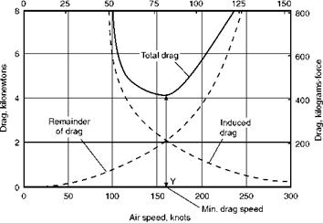
Fig 5.10 Flying for maximum range: how the total drag is made up Induced drag decreases with square of speed. Remainder of drag increases with square of speed. Total drag is the sum of the two; and is a minimum when they are equal.

Another way of thinking of the significance of flying with minimum drag is to divide the total drag into induced drag – which decreases in proportion to the square of the speed – and all-the-remainder of the drag – which increases in proportion to the square of the speed. This idea is well illustrated in Fig. 5.10 and in the numerical examples (Appendix 3).

Flying for maximum range – propeller propulsion

Whether in war or peace, we shall often wish to use an aircraft to best advan­tage for some particular purpose – it may be to fly as fast as possible, or as slowly as possible, or to climb at maximum rate, or to stay in the air as long as possible, or, perhaps, most important of all, to achieve the maximum dis­tance on a given quantity of fuel. Flying for maximum range is one of the outstanding problems of practical flight, but it is also one of the best illustra­tions of the principles involved. To exploit his engine and aircraft to the utmost in this respect, a pilot must be not only a good flier, but also an intel­ligent one.

The problem concerns engine, propeller and aircraft; it also concerns the wind. In this book we are interested chiefly in the aircraft, but we cannot solve this problem, and indeed we can solve few, if any, of the problems of flight, without at least some consideration of the engine and the propeller, or jet, or rocket, or whatever it may be, and how the pilot should use them to get the best out of his aircraft. As for the wind, we shall, as usual in this subject, first consider a condition of still air.

The object in any engine regardless of type is to burn fuel so as to get energy and then to convert this energy into mechanical work. In order to get the greatest amount of work from a given amount of fuel, we must, first of all, get the maximum amount of energy out of it, and then we must change it to mech­anical work in the most efficient way. Our success or otherwise will clearly depend to some extent on the use of the best fuel for the purpose, and on the skill of the engine designer. But the pilot, too, must play his part. To get the most heat from the fuel, it must be properly burned; this means that the mixture of air to fuel must be correct. In a piston engine, what is usually called ‘weak mixture’ is, in fact, not so very weak, but approximately the correct mixture to burn the fuel properly. If we use a richer mixture, some of the fuel will not be properly burned, and we shall get less energy from the same amount of fuel: we may get other advantages, but we shall not get economy. Both the manifold pressure and the revolutions per minute will affect the efficiency of the engine in its capacity of converting energy to work. The problem of the best combination of boost and rpm, though interesting, is outside the scope of this book and at this stage, too, the principles of the recip­rocating and turbine engine begin to differ, while the rocket or ramjet has not got any rpm! For the reciprocating engine we can sum up the engine and pro­peller problem by saying that, generally speaking, the pilot will be using them to best advantage if he uses weak mixture, the highest boost permissible in weak mixture, and the lowest rpm consistent with the charging of the elec­trical generator and the avoidance of detonation. All this has assumed that he has control over such factors, and that the engine is supercharged and that the propeller has controllable pitch. Without such complications, the pilot’s job will, of course, be easier; but the chances are that, whereas a poor pilot may get better results, the good pilot will get worse – far, far worse.

Before we leave the question of the engine and propeller, let us look at a problem which affects all engines in which fuel is burnt to give mechanical energy – not just piston engines.

The problem is that we cannot convert all the energy produced by burning the fuel into mechanical work, however hard we try. What is more, although in a sense we are always trying to do this (and then call the engine inefficient because we do not succeed!) we know quite well why we cannot and never will do it – it is just contrary to the laws of thermodynamics, the laws that govern the conversion of energy into mechanical work. All we can get, even in the best engines and in the hands of the best pilots, is something like 30 per cent of this figure. From each litre of fuel we can expect to get about 31 780 000 joules of thermal energy and hence only 0.3 X 31 780 000 joules i. e. about 9 500 000 joules or newton metres of mechanical energy.

This is what the engine should give to the propeller; and we may lose 20 per cent of it due to the inefficiency of the propeller, and so the aircraft will only get about 80 per cent of 9 500 000, i. e. about 7600 000 joules, or newton metres.

It still seems a large figure – it is a large figure – but, as we shall see, it will not take the aircraft very far. However at this stage we are not so much con­cerned with the numerical value, as with the unit, and to think of it in the form of the newton metre. We have found that a litre of fuel, if used in the best poss­ible way (we have said nothing about how quickly or slowly we use it) will give to the aircraft so many newton metres. Suppose, then, that we want to move the aircraft the maximum number of metres, we must pull it with the minimum number of newtons, i. e. with minimum force. That simple principle is the essence of flying for range.

Tet us examine it more closely. It means that we must fly so that the pro­peller gives the least thrust with which level flight is possible. Feast thrust means least drag, because drag and thrust will be equal.

Effect of weight

The table was worked out for a constant weight of 50 kN. What will be the effect of changes of weight such as must occur in practical flight owing to fuel consumption, etc.? The answer to this is not quite so simple.

Suppose the weight is reduced from 50 kN to 40 kN. At the same indicated air speed, the angle of attack would be the same, and the lift would be the same as previously, i. e. 50 kN. This would be too great. Therefore, in order to reduce the lift, we must adjust the attitude, so that the wings strike the air at a smaller angle of attack, or we must reduce the speed, or both. Whatever we do, we shall get a slightly different relationship between air speed and angle of attack: the reader is advised to work out the figures for a weight of 40 kN. Although the relationship will differ from that for 50 kN weight, it will again remain constant at all heights for the same indicated speeds. To sum up the effect of weight, we can say that the less the total weight of the aircraft, the less will be the indicated air speed corresponding to a given angle of attack. A little calculation will show that the indicated air speed for the same angle of attack will be in proportion to the square root of the total weight.

Effect of height

Table 5.1 was worked out for ground level conditions. What will be the effect of height on the relationship between air speed and angle of attack? The answer, once it is understood, is simple – but very important.

Whatever the height, the air speed indicator reading is determined by the pressure ipV1. In this expression, У is the true air speed. As has already been explained in Chapter 2, when the air speed indicator reads 200 knots at 3000 m, it simply means that the difference in pressure between pitot and static tubes (i. e. IpV2) is the same as when the air speed was 200 knots at ground level. Now, it is not only the pitot pressure tha^depends on ipV2; so do the lift and the drag. Therefore, at the same value of IpV2, i. e. at the same indicated speed, the lift and drag will be the same as at ground level, other things (such as Cj) being equal. Therefore the table remains equally true at all heights, pro­vided the air speed referred to is the indicated speed, and not the true speed. Thus the angle of attack, or the attitude of the aeroplane to the air, is the same in level flight at all heights, provided the indicated air speed remains the same.

Level flight at different air speeds

So far we may seem to have assumed that there is only one condition of level flight; but this is not so. Tevel flight is possible over the whole speed range of the aeroplane, from the maximum air speed that can be attained down to the minimum air speed at which the aeroplane can be kept in the air, both without losing height. This speed range is often very wide on modern aircraft; the maximum speed may be in the region of 1000 knots or even more, and the minimum speed (with flaps lowered) less than 150 knots. Mind you, though level flight is possible at any speed within this range, it may be very inadvis­able to fly unduly fast when considerations of fuel economy are involved, or to fly unduly slowly if an enemy is on your tail! There is nearly always a correct speed to fly according to the circumstances.

Relation between air speed and angle of attack

An aeroplane flying in level flight at different air speeds will be flying at dif­ferent angles of attack, i. e. at different attitudes to the air. Since the flight is level, this means different attitudes to the ground, and so the pilot will be able to notice these attitudes by reference to the horizon (or to the ‘artificial horizon’ on his instrument panel).

For every air speed – as indicated on the air speed indicator – there is a cor­responding angle of attack at which level flight can be maintained (provided the weight of the aeroplane does not change).

Let us examine this important relationship more closely. It all depends on our old friend the lift formula, L = CL. jpV2 . S . To maintain level flight, the lift must be equal to the weight. Assuming for the moment that the weight remains constant, then the lift must also remain constant and equal to the weight. The wing area, S, is unalterable. Now, if we look back, or think back, to Chapter 2 we will realise that TpV2 represents the difference between the pressure on the pitot tube and on the static tube (or static vent), and that this difference represents what is read as air speed on the air speed indicator; in other words, the indicated air speed. There is only one other item in the formula, i. e. CL (the lift coefficient). Therefore if IpV2, or the indicated air speed, goes up, CL must be reduced, or the lift will become greater than the weight. Similarly, if ~_p V2 goes down, CL must go up or the lift will become less than the weight. Now CL depends on the angle of attack of the wings; the greater the angle of attack (up to the stalling angle), the greater the value of CL. Therefore for every angle of attack there is a corresponding indicated air speed.

This is most fortunate, since the pilot will not always have an instrument on which he can read the angle of attack, whereas the air speed indicator gives him an easy reading of air speed. That is why a pilot always talks and thinks in terms of speed, landing speed, stalling speed, best gliding speed, climbing speed, range or endurance speed, and so on. The experimenter on the ground, on the other hand, especially if he does wind tunnel work, is inclined to talk and think in terms of angle, stalling angle, angle of attack for flattest glide, longest range, and so on. This difference of approach is very natural. The pilot, after all, has little choice if he does not know the angle of attack but does know the speed. To the experimenter on the ground, speed is rather meaningless; he can alter the angle of attack and still keep the speed constant – something that the pilot cannot do. But, however natural the difference of outlook, it is unfor­tunate; and it is undoubtedly one of the causes of the gap between the two essential partners to progress, the practitioner and the theorist.

Air speed, metres per second

Level flight at different air speeds

Air speed, knots

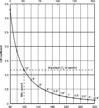
Fig 5.9 Air speed, lift coefficient and angle of attack Aeroplane of weight 50 kN (5100 kgf); wing area 25.05 m2; wing loading 1920 N/m2 (196 kgf/m2); aerofoil section characteristics Figs 3.13, 3.15, 3.16 and 3.17.

Let us examine our general statement more critically by working out some figures. Suppose the mass of an aeroplane is 5100 kg (so that its weight will be approximately 50 000 newtons and that its wing area is 26.05 m2, i. e. a wing loading of about 1920 N/m2. Assume that the aerofoil section has the lift characteristics shown in the lift curve in Fig. 3.13. Consider first the ground level condition, the air density being 1.225 kg/m3.

Whatever the speed, the lift must be equal to the weight, 50 kN; but the

lift must also be equal to CL. ^pV2. S, so

50 000 = С, X – X 1.225 X V2 X 26.05 L 2

from which

CL = 3134/V2

Now insert values for V of 60, 80, 100 and other values up to 300 knots, con­verting them, of course, to m/s, and work out the corresponding values of CL; then by referring to Fig. 3.13 read off the angle of attack for each speed. The result will be something like that shown in Table 5.1 and in Fig. 5.9. The angles given in the table are approximate since all the values are small.

Now let us see what this table and graph mean; we shall find it very inter­esting. In the first place at speeds below about 100 knots, the lift coefficient needed for level flight is greater than the maximum lift coefficient (1.18) pro­vided by the aerofoil, therefore level flight is not possible below this speed. Secondly, as the speed increases to 120, 140, 160 knots, etc., the angle of attack decreases from 15° to 9°, 6°, 4°, etc.; and for each speed there is a cor­responding angle of attack. We should notice, in passing, that at comparatively low speeds there is much greater change in angle of attack for each 20 knots increase in air speed than there is at the higher speeds, e. g. the angle of attack at 120 knots is 6° less than at 100 knots, whereas at 280 knots it is only 0.2° less than at 260 knots. This change in proportion is interesting, and is one of the arguments for an angle of attack indicator, which is sensitive at low speeds, which is just where the air speed indicator is most unsatisfactory.

We could, of course, continue Table 5.1 speeds higher than 300 knots, and we should find that we needed even smaller lift coefficients, and even more negative angles of attack (though never less than 21.8° since at this angle there would be no lift, whatever the speed). But at this stage we must begin to con­sider another factor affecting speed range, namely the power of the engine. What we have worked out so far is accurate enough, provided we can be sure

Table 5.1 Angle of attack derived from airspeed

knots

Air speed

m/s

V2

CL = 3134/V2

Angle of attack

60

30.8

949

3.31

80

41.2

1697

1.85

100

51.5

2652

1.18

15°

120

61.8

3819

0.82

140

72.0

5184

0.60

160

82.4

6790

0.46

180

92.6

8580

0.37

2.6°

200

103.0

10 600

0.30

1.8°

220

113.2

12 800

0.24

240

123.7

15 400

0.20

0.5°

260

134.0

18 000

0.17

0.2°

280

144.0

20 740

0.15

300

154.0

23 700

0.13

-0.4°

of obtaining sufficient thrust. It may be that at speeds of 300 knots or above or, for that matter, at 100 knots or below, we shall not be able to maintain level flight for the simple reason that we have not sufficient engine power to overcome the drag. So the engine power will also determine the speed range, not only the top speed, but also to some extent the minimum speed.

If the reader thinks that the minimum speed of this aeroplane is rather high, we should perhaps point out, first, that we have not used flaps; secondly, that the aerofoil does not given a very high maximum lift coefficient; and, thirdly, that it has a fairly high wing loading, or ratio of weight to wing area, which, as we shall see later, has an important influence on minimum speed. All we wish to establish now is the relationship between air speed and angle of attack, and this is clearly shown by Table 5.1.

Finding the tail load

This conclusion only applies when there is no force on the tail plane. When there is such a force the problem is slightly more complicated, but can still be solved by the principle of moments. Consider a further example –

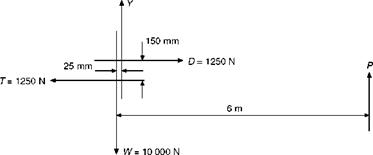
An aeroplane weighs 10 000 N; the drag in normal horizontal flight is 1250 N; the centre of pressure is 25 mm (0.025 m) behind the centre of gravity, and the line of drag is 150 mm (0.15 m) above the line of thrust. Find what load on the tail plane, which is 6 m behind the centre of gravity, will be required to maintain balance in normal horizontal flight.

Let the lift force on the main planes = Y newtons

Let the force on the tail plane = P newtons (assumed upwards)

Then total lift = L = Y + P (Fig 5.8)

But L = W= 10 000 N

:.Y+P= 10 000 N (1)

Also T = D = 1250 N (2)

Take moments about any convenient point; in this case perhaps the most suit­able point is 0, the intersection of the weight and thrust lines.

Nose-down moments about 0 are caused by Y and P

W and T will, of course, have no moments about 0,

Finding the tail load

Fig 5.8 The four forces and the tail load

So total nose-down moments = 0.025 Y + 6 P

(all distances being expressed in metres) Tail-down moment about 0 is caused by D only,

So total tail-down moment = 0.15 D 0.025 Y +6P = 0.15 D

i. e. Y + 240 P = 6 D (3)

But from (1), Y + P = 10 000

2 39P = 6D – 10 000 But from (2), D = 1250

239P = 6 X 1250 – 10 000 = 7500 – 10 000 = -2500

P = -(2500/239) = -10.4 N

Therefore a small downward force of 10.4 N is required on the tail plane, the negative sign in the answer simply indicating that the force which we assumed to be upwards should have been downwards.

The student is advised to work out similar examples which will be found in Appendix 3 at the end of the book.

Methods of varying the tail plane lift

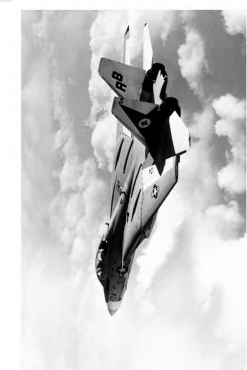
For many years, the most common method of altering the tail plane lift was to provide a hinged rear portion called an elevator. Moving this up or down alters the camber of the surface, and thus changes the lift. However, in supersonic flight, changes of camber do not produce much of a change in lift, and it is better to move the whole tail surface as a single slab. A slab type tail surface may be seen in Figures 5G and 5H (overleaf). The moving slab tailplane is nowadays sometimes used even on low-speed aircraft as there are structural and manufacturing advan­tages to this type of tail. On some aircraft, particularly large transports, the two approaches may be combined. The whole tailplane can be moved, mainly to provide for trimming, and a hinged elevator is also used, mainly for control and manoeuvre.

Conditions of balance considered numerically

We have so far avoided any numerical consideration of the forces which balance the aeroplane in straight and level flight; in simple cases, however, these present no difficulty.

When there is no load on the tail plane the conditions of balance are these –

1. Tift = Weight, i. e. L = W.

2. Thrust = Drag, i. e. T = D.

3. The ‘nose-down’ pitching moment of L and W must balance the ‘tail – down’ pitching moment of T and D.

Methods of varying the tail plane lift

Fig 5F High tail

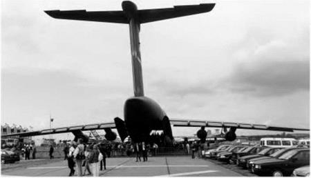
The tail of a Lockheed C-5 Galaxy. The elevators are split into a number of sections to provide redundancy for reasons of safety.


Fig 5G Low tail

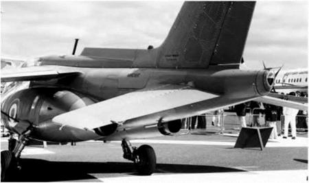
The Alpha-Jet has a relatively low tail plane with pronounced anhedral.


Methods of varying the tail plane lift

Methods of varying the tail plane lift

The two forces, L and W, are two equal and opposite parallel forces, i. e. a couple; their moment is measured by ‘one of the forces multiplied by the per­pendicular distance between them’. So, if the distance between L and W is x metres, the moment is Lx or Wx newton-metres.

Similarly, T and D form a couple and, if the distance between them is у metres, their moment is Ту or Dy newton-metres.

Therefore the third condition is that –

Lx (or Wx) = Ту (or Dy)

To take a numerical example: Suppose the mass of an aeroplane is 2000 kg. The weight will be roughly 20 000 N. T = W. So T = 20 000 N.

Now, what will be the value of the thrust and drag? The reader must beware of falling into the ridiculous idea, which is so common among stu­dents, that the thrust will be equal to the weight! The statement is sometimes made that the ‘Four forces acting on the aeroplane are equal’, but nothing could be farther from the truth. L = W and T = D, but these equations cer­tainly do not make T = W. This point is emphasised for the simple reason that out of over a thousand students to whom the author has put the question, ‘How do the think the thrust required to pull the aeroplane along in normal flight compares with the weight?’ more than 50 per cent have suggested that the thrust must obviously equal the weight and over half the remainder have insisted that, on the other hand, the thrust must be many times greater than the weight! Such answers show that the student has not really grasped the fun­damental principles of flight, for is not our object to obtain the maximum of lift with the minimum of drag, or, what amounts to much the same thing, to lift as much weight as possible with the least possible engine power? Have we not seen that the wings can produce, at their most efficient angle, a lift of 20, 25 or even more times as great as their drag?

It is true that there is a great deal of difference between an aeroplane and a wing; for whereas a wing provides us with a large amount of lift and a very much smaller amount of drag, all the other parts help to increase the drag and provide no lift in return. Actually it is not quite true to say that the wings provide all the lift, for by clever design even such parts as the fuselage may be persuaded to help. Efforts to increase the lift may be well worth while, but even total increase of lift from such sources will be small, whereas the addition of the parasite drag of fuselage, tail and undercarriage will form a large item; in old designs it might be as much, or even more than the drag of the wings, but in modern aircraft with ‘clean’ lines the proportion of parasite drag has

Fig 5H Slab tail planes (opposite)

(By courtesy of the Grumman Corporation)

Large slab tail planes and twin fins are evident on this photograph of the F-14.

been much reduced. None the less it may result in the reduction of the lift/drag ratio of the aeroplane, as distinct from the aerofoil, down to say 10, 12 or 15.

So it will be obvious that the ideal aeroplane must be one in which there is no parasite drag, i. e. in the nature of a ‘flying wing’; we should then obtain a lift some forty times the drag. At present we are a long way off this ideal except for high-performance gliders.

In our numerical example, let us assume that the lift is ten times the total drag, this being a reasonable figure for an average aeroplane. Then the drag will be 2000 N; so thrust will also be 2000 N. This means that an aeroplane of weight 20 000 N can be lifted by a thrust of 2000 N; but the lift is not direct, the work is all being done in a forward direction – not upwards. The aeroplane is in no sense a helicopter in which the thrust is vertical, and in which the thrust must indeed be at least equal to the weight.

To return to the problem –

L = W = 20 000 N

T = D = 2000 N (This is merely an approximation for a good type of aeroplane)

Lx = Ту

Подпись: and x
Methods of varying the tail plane lift

So 20 000 x = 2000 у

So if T and D are 1 metre apart, L and W must be 1/10 metre apart, i. e. 100 mm. In other words, the lines of thrust and drag must be farther apart than the lines of lift and weight in the same proportion as the lift is greater than the drag (Fig. 5.7).

L = 20 000 N

D = 2000 N

Подпись: x metres

у metres

T= 2000 N

W= 20 000 N

Подпись: Fig 5.7Balance of forces – no load on tail