Now we are properly airborne, it is time to leave the airfield and try a few manoeuvres. We start by banking about 10° to the left to make a gentle turn on to a course of 90°. We are now approaching 3000 ft and need to level off into straight and level flight. Nose down, let the speed build and, as our cruising speed of 90 knots approaches, we gently throttle back to the cruise engine setting of 2300 rpm. Finally, when things are nicely settled, we use the trim to remove the control force and find the aircraft flies quite happily ‘hands off’. Every 15 minutes or so we do the ‘FREDA’ checks to make sure that all is well:
Fuel – have we got enough?
Radios – on correct frequencies?
Engine – temperature and pressures OK? Pull out the carburettor heat to the on position and check for a small fall in engine speed and a return to the previous speed when the carburettor heat is turned off. This check ensures that we haven’t inadvertently started icing up the engine.
Direction finder – does it read the same as the magnetic compass? (The DF is a gyroscopic instrument and tends to drift slightly with time).
Altimeter – is it set correctly and are we at the correct height?
Checks complete. Now to try a few manoeuvres. First we pull back slightly. After an initial climb, the aircraft settles to a lower speed of 86 knots. We can reset the throttle to remove the subsequent tendency to slowly gain height but as we were flying fairly near the minimum power setting, not much movement is necessary. To speed up we do the opposite; yoke forward and increase throttle slightly to prevent sink. Unlike a car, we do not use the throttle as the speed control, although it may need some slight adjustment. The main thing is to control the angle of attack with the elevators – pull back to slow up and push forward to increase speed.
Now let’s try a descent to 2500 ft. Throttle back to 1500 rpm. When we do this we have to remember that carburettor icing can be a real danger, even on a fairly hot day. We don’t want the engine quitting on us; we have only got one! So we pull on the carburettor heat control, which directs the engine air over the hot exhaust manifold, before it enters the carburettor. We need some slight control input to cope with the change in engine torque and the change in pitching moment, due to its offset thrust line. When we have settled into a steady descent (a descent rate of about 500 ft/min on the rate of climb indicator) we can again trim the aircraft, so that it will fly ‘hands off’ in the steady descent. In spite of these other small effects, the main effect of the power change is that the aircraft settles into a steady descent. As 2500 ft approaches, all we need to do is to pull back slightly to level out and return the throttle to the cruise setting (don’t forget to turn off the carburettor heat) and finally retrim in level flight.
Now climb back to 3000 ft. Full power first – we don’t want to lose speed. Pull back slightly until the speed falls to 70 knots (best rate of climb). Trim when things have settled. As we reach 3000 ft, push forward into level flight. Then, as we reach the cruising speed of 90 knots retrim when things have settled. Quite simple in a well-behaved aircraft like this!
Next a stall. Throttle back to idle (carburettor heat to on). Gradually pull back so that no height is lost. Notice as the speed reduces that the controls start to have a ‘soggy’ feel. As the speed drops off and we continue to raise the nose the increased angle of attack causes the suction peak on the top of the wing to move towards the leading edge. Eventually we here a buzz as it triggers the stall warning device which detects the pressure near the wing leading edge. When we hear this, we are only a few knots above stalling speed. Normally we would push the yoke forward to reduce the angle of attack (yes, even if we are near the ground!). Now, however, we press on raising the nose, as we wish to experience a stall. We are now down to 45 knots, and, in spite of our efforts to raise the nose, it drops and we have stalled. We entered the stall flying straight and level, so nothing very exciting happens. To recover; push the yoke forward, turn carburettor heat off and select full throttle. As the speed builds up to the cruising speed we pull back to level out and reduce the throttle to the cruise setting.
We tried a gentle turn when we were leaving the airfield circuit in a climb. Now we will try to do some level turns. As with most flying, the secret is to keep your eyes on the horizon. We check for other aircraft from right to left (the direction in which we are going to turn), bank gently to 10° (indicated by the scale outside the artificial horizon) and try to keep the line of the horizon constant in the windshield. Note that, as we get to the required bank angle, we have to remove the input to the ailerons and even reverse them slightly to hold the correct angle. This is because the wing on the outside of the turn has a slightly higher airspeed, so the centre of lift moves slightly towards this wing, promoting a steeper bank than was aimed for. However, the correction is made instinctively and careful observation is needed to see what has happened.
A glance at the altimeter shows a slight descent, so a little backpressure to bring the nose up. (Note that the rate of climb indicator has a response that is too slow to be of use to us here). A glance at the ball in the turn and slip indicator shows a small degree of sideslip. Because the wing symmetry has been disturbed by the increase in speed of the outer wing, there is a slight tendency for the aircraft to yaw away from the turn due to the asymmetric vortex drag. This is countered by a bit of left rudder. It sounds simple but things can get a bit confusing with an over-correction sending the sideslip the other way. Thankfully a simple rule resolves the problem; if the ball is on the right, add right rudder and vice versa.
Now let’s be a bit more adventurous and try a steep (60° bank angle) turn. This seems a lot more hairy as we are pulling a load factor of 2 (remember how the load factor goes up in a turn). The principles are the same but a lot more difficult to control under these circumstances. Additionally we will need to add some power or we will not be able to sustain speed and height. As we know, the power required goes up in a turn. In the shallower turn we were able to leave the throttle as it was and trade off a bit of speed (as we were above the speed for minimum power). Now we need a bit more from the engine to keep us going round at constant height. A check for other aircraft and round we go. The increased load on our bodies makes it quite difficult and, even when we have established a nice level turn, it is not easy to roll out on exactly the right heading and throttle back to re-establish straight and level flight.
Engine to 2000 rpm and a quick final check on engine and instruments, release brakes and throttle fully forward. A quick glance to make sure the ASI registers the increasing speed and, as the aircraft gathers speed, we use the pedals to counter any swing and keep the nose pointing down the runway. The controls begin to become more effective as the speed increases, so we ease the ailerons and the backpressure on the elevators. As the speed reaches 55 knots, we pull back gently and now we are climbing away at full throttle and adjust the elevators to give a steady climbing speed of 60 knots, close to the speed that gives us the best angle of climb, to clear any obstacles.
Once things have settled down, to remove the force on the yoke, we trim, using the trim wheel that operates a small tab on the right hand elevator, and wait until the altimeter shows that we are 500 ft above the airfield. Then we push forward slightly and settle to 70 knots (the speed for best rate of climb) and retrim, keeping the horizon at a constant position in the windscreen. It might seem odd to increase the rate of climb by lowering the nose and increasing the speed but a quick glance at the vertical speed indicator shows that we are, in fact, climbing faster than before. It will be a good idea to look again at Chapter 7, when we get down, to work out the reason why.
Our aircraft is parked into wind. We pull back on the yoke to lighten the load on the nose wheel and push the throttle forward until we start to move. More checks now. Do the brakes work? We throttle back and try them, repeating for both left hand and right hand control positions. Now we park into wind for the power checks. First we check that oil pressure and temperature are OK. Next set 1700 rpm and make sure these remain within limits and another check on the magnetos before making sure the engine does not quit when we set it to idle.
Now we are almost ready. We make a final check that all switches are set correctly, the flaps are up, mixture rich and carburettor heat off and another quick check to see the controls move correctly as we pull back for the elevators and turn the wheel for the ailerons. Now, at last, we can taxi to the holding point on the runway. As we taxi we position the ailerons to keep the into-wind wing down and the elevators set to reduce the load on the nose wheel as much as possible. At the holding point we stop to tell the tower that we are about to line up on runway 22L, look for any aircraft on the approach, release the brakes and line up on the runway centre line.
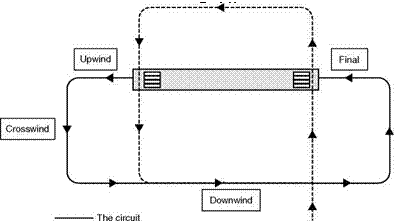
Again, unlike a car, we cannot just throw our cases into the back and hope for the best. The basic aircraft is carefully weighed so that the weight and position of the centre of gravity are both known. We have to worry about the move – able weights and do weight and balance calculations for the loads we are carrying on this flight. Every aircraft has a flight manual and it is this that will tell us if our loading is within safe limits for the aircraft. We are not going far – we will be in uncontrolled airspace and visibility and forecast are good, so we will not need to file a flight plan. It is still a good idea to plan what we intend to do, though. Runway in current use is 22T (the 22 means the heading is about 220° on the DI), so we will take off southwest towards the city, turn left towards the east before we get to the built-up area and try some turns, stalls and a few other manoeuvres. We will then rejoin the circuit and land – a total flight time of perhaps 50 minutes.
Now for our detailed pre-flight checks. We first inspect the paperwork to make sure our particular aircraft has up-to-date service records, insurance, etc. Taking our checklist, we then go to the aircraft. First we switch off the radios and then switch on the master switch and the switches for all the systems we are going to test – the flashing anti-collision beacon, the navigation lights, the landing lights and the pitot heater. We walk round the aircraft, checking that all these systems are working, then we return to the cockpit and test the flaps before switching everything off again.
Now we walk slowly round the aircraft, checking such things as the condition of the tyres and brakes, the condition of the surfaces, the control hinges, etc. We also make sure that, when we waggle the controls, the main yoke moves in the correct direction – misrigging has been known! As we come to the leading edge of the starboard wing we notice a small hole. This is the stallwarning device. As an aerofoil approaches the stall the suction at the leading edge gets stronger. The stall warning device sounds a buzzer in the cockpit when the aerofoil is dangerously close to the stall. We test that this is working by sucking gently at the hole. Now we are at the nose we check the engine oil level and the condition of the propeller. We must also check the fuel. First we take samples to make sure it has not been contaminated by water and then we clamber on to a step on the strut of each wing in turn to dip the tank and make sure we have enough fuel for the flight – the electrical gauges may fail and there are no filling stations at 3000 ft. Clearly the last pilot filled it up before he parked it, so we do not have to worry about a trip to the pumps.
Nearly there now! We get into the cockpit, plug our headsets in ready for use and check that the instruments and controls are all in good condition and the first aid and fire extinguisher are to hand and in date. Then we adjust the seats and strap ourselves in. Time to start the engine. Fuel on, three strokes of the primer as the engine is cold, mixture rich, carburettor heat cold, throttle to idle, master switch and anti-collision beacon on, check that no circuit breakers have popped out, open the window and shout, ‘Clear prop’ as a warning to the unwary and then turn the key and slowly push the throttle forward. As the engine starts we check that the starter motor has disengaged, that the oil pressure is rising satisfactorily, that the ammeter is reading satisfactorily and that the vacuum gauge is reading in the green area. Now we set the engine speed to 1200 rpm, put on our headsets, make sure the intercom is switched on and that we can hear each other.
A few checks still to do. I told you flying was a thorough business. Magnetos are duplicated for safety, so we make sure that the engine will run happily on either one before returning the switch to both on. Now we set the DI to agree with the magnetic compass and the altimeter to read the approximate height of the airfield (200 ft). Then if we do forget to set it later on it will not be too far out. In this flight we will be measuring altitude with respect to mean sea level (known as QNH). The engine temperature now looks OK and it is time to contact the tower. We are told that runway 22 is in use, that the surface wind is 8 knots from 270° and that the QNH is 1009.0 millibars (remember them?). We repeat back the information, check the altimeter setting and now we are ready to taxi to the runway.
In this chapter we have dealt mainly with what is known as static stability. There are other forms of instability that the designer (and the pilot) has to cope with. These take the form of oscillations or deviations from the desired flight path that vary with time, and are known as dynamic instabilities. They can be a nuisance, nauseating or downright dangerous if left unchecked. An example is the spiral instability referred to earlier in this chapter.
A full description of dynamic stability is beyond the scope of this book, but the reader should be aware that the problems of stability and control are far more complex than the simple outline given here.
Can you answer these?
Questions on stability and control –
1. What would be the characteristics of an aircraft with extreme directional stability and little lateral stability?
2. What would be the characteristics of an aircraft with extreme lateral stability and little directional stability?
3. What is the object of balancing controls?
4. Distinguish between ‘mass’ balance and ‘aerodynamic’ balance.
5. Explain the difficulty of obtaining satisfactory lateral control at large angles of attack.
6. Describe some of the methods which have been tried with a view to overcoming this difficulty.
7. Explain why spoilers are sometimes used at low speeds, and sometimes at high speeds, as an aid to lateral control.
For solutions see Appendix 5.
In the preceding chapters I have tried to explain the principles on which the flight of an aeroplane depends. However, flying an aeroplane is a different thing altogether and in this chapter we will explore what it is actually like to fly a light, low-speed aircraft of the sort that most pilots use when they start their training. During the flight we will use the knowledge we have gained previously to explain what is happening.
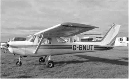
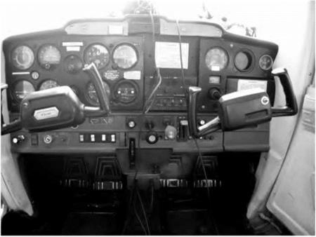
The aircraft we will fly is shown in Fig. 10A. It is a simple aircraft with fixed undercarriage and a fixed pitch propeller driven by a piston engine. Let us have a quick look in the cockpit to see the instruments and controls (Fig. 10B, overleaf). First we notice the main flying instruments – an air-speed indicator (ASI, calibrated in knots), an altimeter (calibrated in ft), a rate of climb
Fig 10A Cessna 152, the aircraft for our flight
indicator (ft/min), and a turn and slip indicator (Fig. 8.6). Then we have an artificial horizon and a direction indicator (DI). Finally, tucked away at the top of the windshield, we have a small magnetic compass.
Next we come to the engine and fuel instruments; the tachometer, which measures the engine speed, is situated on the right hand side of the cockpit, then comes the ammeter (which shows if our electrical generator is working properly) and next to this is a suction gauge. The suction gauge is needed because the artificial horizon and the DI are gyroscopic instruments, which derive their power from engine-supplied suction. If the suction drops below a certain level, these instruments will become unreliable as the gyroscopes slow down and we need warning if this is likely to happen! Under the cluster of main flight instruments we find the fuel gauges (one for each wing tank) and indicators for engine temperature and oil pressure.
The flying controls are quite simple. In front of us is the main yoke. We push this forward to lower the elevators and nose of the aircraft, or pull to raise the nose. We turn the ‘wheel’ to operate the ailerons and bank the aircraft to left or right. At our feet are the pedals, which are used to operate the rudder, and above the pedals the toe-operated differential brakes are situated. On a quadrant, in front of us, there is the flap lever and position indicator. On this aircraft the flaps are electrically operated and so they will not work until the electrical supply is turned on.
Fig 10B The cockpit
The engine controls are quite simple. A push-pull throttle control is provided on the dashboard – push forward to increase engine revs. Apart from this there is a mixture control to compensate for the reduced air density as we climb and a carburettor heat control which we use, particularly at reduced engine speeds, to prevent the carburettor icing up – possibly with disastrous results! As we will only be flying at or below 3000 ft, we will leave the mixture at rich until we eventually want to stop the engine.
To complete the story we need to take a quick look at the navigational equipment. On this aircraft we have a communications radio, a navigational radio (which we shall not use, as we are flying in good visibility and not far from the airfield) and a transponder to allow Air Traffic Control to track our position. Under the fuel gauges and engine instruments is the key-operated switch for the magnetos and engine starter (rather like the ignition switch on a car), together with the light switches and pitot heater switch. Tike the carburettor heater, this prevents the formation of ice but this time on the pitot-static tube, which is vital if we are going to know our correct airspeed. There is also a master switch, which isolates all the electrical systems apart from the magnetos. These provide the spark at the spark plugs and keep the engine running. If there is an electrical fault and we have to switch off the master, at least the engine will not stop!
So far we have spent a long time and the aircraft has not even moved yet. Well, that’s flying! If something goes wrong in a car you can always pull off the road to sort it out. With an aeroplane we have to make sure everything is OK before we start off.
Nowadays all but small aircraft are usually fitted with power-actuated control surfaces which are very easy to operate even on large airliners. Because such controls offer virtually no natural resistance, they are given some form of artificial ‘feel’, a resistance which is designed to increase with flight speed (or more precisely with dynamic pressure) so that the control system feels like a direct mechanical linkage. Without such feel it would be quite literally possible to pull the control surfaces off at high speed.
The control column often incorporates a ‘stick shaker’ which operates when the aircraft approaches a stalled condition. This reproduces the shaking that normally occurs on simple mechanical systems due to the buffeting of the control surfaces caused by turbulence. It is intended to trigger the pilot’s conditioned response. On some aircraft, if the pilot fails to respond correctly by pushing the column forward, the controls take over and a ‘stick pusher’ does the job for him! With the advent of advanced and reliable electronic devices, it has become possible to make control systems of immense complexity that respond smoothly over a very wide range of flight conditions and contain many built-in safety features. In order to prevent loss of control in the event of power failure the systems are usually duplicated, triplicated or even quadrupled.
|


