Category Model Aircraft Aerodynamics

GYROCOPTERS AND AUTOGYROS
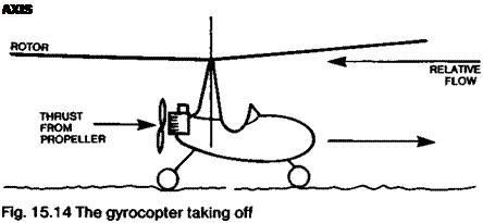
Подпись: AXIS

The autorotation capability of a rotor enabled gyrocopters (autogyros) to fly successfully long before helicopters were developed. Forward motive power is supplied by an ordinary propeller, rigged either as a ‘tractor’ or ‘pusher*, but the lift comes from a freely spinning rotor which may be tilted to provide control, and has the usual hinged and flapping blade system. Take-off may be accomplished by running along the ground until the rotor is turning sufficiently fast to give the required lift The take-off distance can be shortened if the rotor is given a preliminary spin by hand before starting the ground run.

Juan de Cierva’s autogyros of pre-1939 times were capable of near vertical take-off because a drive shaft was connected to the rotor with a clutch from the main engine. With blades set in zero collective pitch the rotor was spun up to high speed and allowed then to turn freely while the drive was declutched, all the engine power turning the propeller. The rotor was then set to positive pitch and the craft would leap into the air, quickly accelerating horizontally under the propeller thrust Landings were by gliding descent and the ground run was very brief.

Model autogyros are occasionally seen and all the same principles apply to them as to the full-sized aircraft. Although there is no strong torque reaction, as there is with a helicopter, the autogyro rotor does tend to turn the fuselage because of the friction of the main bearings, which cannot be entirely removed. It is therefore necessary to provide some aerodynamic means of aligning the fuselage with the airflow and this requires at least a vertical fin to give a weathercocking action. A rudder is also useful. Other wing and tail-like surfaces may also be used to supplement the rotor lift and control the attitude in flight.

RETREATING BLADE STALL

The limit to a helicopter’s forward speed is reached when the retreating blade’s outer parts reach their stalling angle.

15.4 AUTOROTATION

If a helicopter suffers engine failure it may be trimmed for autorotation, which is equivalent to gliding with a fixed wing aircraft. In this condition, instead of air being

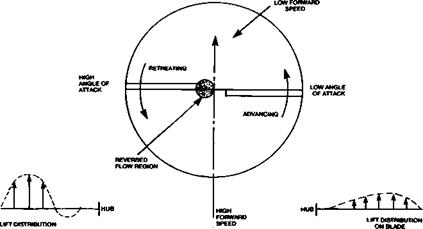
Fig. 15.12 Reversed flow on retreating blade

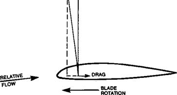
Подпись: Fig. 15.13 Forces on autorotating blade
Подпись: LIFT Г '1 VERTICAL

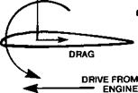
drawn down through the rotor disc the rotor as a whole is inclined at a slight positive angle to the airflow, which streams upwards through the disc. The conditions on an individual blade are such that they continue to turn rapidly enough to provide support. As shown in Figure 15.13, the forces on an autorotating blade are identical with those on the whole wing of a glider, a component of the lift being set off against the drag to keep the aerofoil moving through the air. The helicopter as a whole then may glide some distance before being compelled to touch down ami it may be steered with the cyclic pitch control.

RETREATING BLADE FLOW REVERSAL

The forward speed of the helicopter at any time may be compared with the rearward speed of any segment of the retreating blade. The innermost part of the blade moves aft relatively slowly compared to the forward velocity of the entire rotor system. Even at slow flight speeds, some part of the rotor on the retreating side will therefore experience reversed flow. Since the first few percent of the blade is invariably occupied with hub mechanism, pitch control pushrods and hinges or flexible support, the effect is of little importance when the forward speed is slow.

As the helicopter accelerates towards its maximum flight speed, even though the rotor speed as a whole may increase, the area of blade which comes under reversedlflow extends further outwards (Figure 15.12). When this begins to affect the aerofoil shaped part of the blade, not only does this segment produce no supporting lift but, because the blade is now meeting the air backwards at a negative angle of attack, a downforce results. Further out still there is a point on the blade where there is no relative movement of the air (other than some outward dragging because of centrifugal forces). Beyond this, the blade begins again to produce lift.

The outer parts of the retreating blade at high speed are required to produce as much lift, at their lower relative airspeed, as the entire advancing rotor on the other side, plus an additional quantity to compensate for the downforce in the reversed flow region. To do this, blade flap increases die angle of attack on the retreating side considerably.

BLADE FLAP

In translational flight, the blade on one side of the line of movement, now called the advancing blade, meets the air at a higher velocity than the other retreating, blade. Since, at a given angle of attack, lift depends on flow speed, this would cause an effect on the helicopter rotor exactly analogous to the ‘P’ effect on propellers when these are not aligned with the flight direction (Fig. 15.10). To prevent this, it is essential to reduce the angle of attack of the advancing blade and increase that of the retreating blade, to

Fig. 15.9 Gyroscopic 90° out-of­phase reaction

(LIFT DEPENDS ON SPEED SQUARED]

Fig. 15.10 Lateral imbalance

Fig. 15.11 Blade flapping to equalise lift in forward flight

maintain equal forces on both sides. This is achieved by allowing the blades to hinge, or flex, up and down freely under the air loads they meet. As the advancing blade rises, its angle to the airflow is reduced (Figure IS.11). Conversely, as it moves round to the retreating position, it flaps down, so increasing its angle of attack. The total lift force is thus equalised laterally. Blade flapping is automatic and self adjusting to a large extent, since any untoward rolling force causes the blades to hinge up and down rather than tilting the helicopter as a whole.

CYCLIC PITCH CONTROL

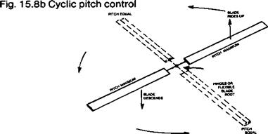
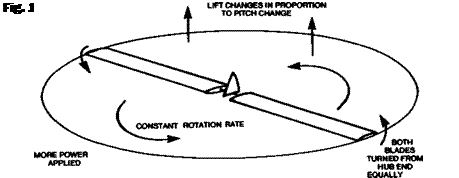
It is possible to tilt the rotor of a helicopter, relative to the body, by changing the alignment of the entire drive shaft and even the engine, which can be suspended on gimbals to permit this. The complications are considerable and there is a much better way of tilting the plane of rotation which involves cyclic pitch change of the rotor blade’s angles. By means of a swash plate or some equivalent device, as each blade rotates it is turned progressively to a different pitch so that in relation to the air it reaches a maximum angle of attack, and so produces more lift, at one radial position, and a minimum angle at the diametrically opposite pole. In the case of a two bladed rotor, one blade is at the maximum when the other is at the minimum. The cyclic pitch changes are superimposed on the collective pitch so that each blade maintains the same average pitch and lift as it rotates and the total lift of the entire rotor system is maintained at that required to support the aircraft, while at any particular place round the circle, an individual blade may be at lower or higher angle of attack than the mean.

The individual blades are hinged near the hub, or are mounted on a supporting member which is flexible so that the cyclic pitch changes cause the blades to ride up when the pitch is large and descend when it is less.

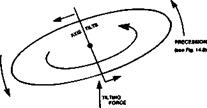
Подпись: Fig. 15.8a Cyclic pitch tilts rotor

Viewing the entire rotor disc as a whole, somewhat like a large wheel, the cyclic pitch change applies a force tending to change the rotational axis. There is a gyroscopic reaction which is 90 degrees out of phase with the tilting force. Hence the actual disc tilt is 90 degrees out of phase with the cyclic pitch control. This kind of effect appears on

propellers too, as shown in Figure 14.18, where a ‘tail up’ change of the axis produces a yaw to the side. If the diagram or Fig. 14.18 is imagined as representing a helicopter rotor with the disc more or less horizontal, the effect of cyclic pitch may be more readily understood. (An even more impressive demonstration may be done with a bicycle wheel. If the wheel, detached from its supporting frame, is spun rapidly in a horizontal plane and an attempt is made to tilt it by applying a force in one direction, the actual response is a tilt 90 degrees out of phase – i. e. a sideways tilting effort producing a forward or backward tilt.)

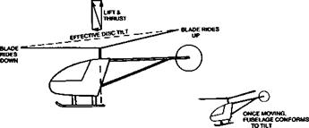
Once the helicopter is moving in the desired direction, the drive axis aligns itself with the new angle of the disc, so the fuselage of the aircraft in forward flight takes up a nose – down attitude. Relative to the aircraft, the disc is then not tilted and the cyclic pitch control may be returned to neutral, being used thereafter only to trim for the desired speed. This is an important feature of controlling helicopter flight, since the normal ‘down trim’ required with a stable, fixed wing aircraft is not required or desirable with a helicopter. In this sense, helicopters tend to be neutrally stable. (Refer to Figure 12.1)

TRANSLATIONAL FLIGHT

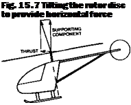
A helicopter relies on its main rotor for thrust as well as lift. By tilting the plane of rotation (Figure 15.7) the lift vector is inclined forwards (or in another direction) and the resolved forces then move the aircraft horizontally. The direction of the motion is not dependent on the alignment of the fuselage, but only on the tilting of the rotor disc. Thus helicopters can move sideways or backwards with ease. To save fuselage drag in normal operations, the tail rotor is used to align the body with the flight direction.

Once moving, less engine power is needed, at a given altitude, than when hovering. The situation is roughly comparable to the efficiency of a propeller when not moving forward and when flying fast. In a given unit of time, a larger mass of air moves through the actuator disc, so the thrust, or lift, required can be obtained by giving a smaller


Fig. 15.6 The vortex ring

Подпись: Fig. 15.7 Tilting the rotor disc to provide horizontal force

momentum to a large mass instead of a large momentum to the smaller quantity of air. Because of this, helicopters are capable of very much higher flight ceilings when in translational flight than hovering. In marginal take-off conditions it is possible to use the ground effect to get off the ground and immediately to move forward, taking advantage of the increased efficiency to gain height.

VERTICAL DESCENT: VORTEX RINGS

With reduced power and/or less collective pitch, the helicopter can descend vertically. In doing so, it tends to fly into its own slipstream and if the rate of sinking is rapid, it may come to equal, or nearly equal, the rotor downwash. In this rather dangerous condition not only is the air very turbulent, but a vortex ring may easily develop. The slipstream from the rotor is at high pressure while above the blades the pressure is low. The air flows up round the limits of the rotor disc and re-enters the low pressure zone, to be drawn down

POWER INCREASED TO OVERCOME

Fig. 15.4 Vertical climb.«creased rotor drag
again through the rotor. The helicopter then is effectively flying in the middle of a strong downdraught of its own making. The entire vortex ring tends to become a self-contained system and sinks through the surrounding air rapidly. (Figure 15.6. The situation is closely analogous to the ascent of a buoyant ring-vortex thermal.) Fortunately, the danger of a crash can be avoided by trimming for a forward (or any other direction) motion so that the rotor does not drop into its own slipstream but constantly enters new, relatively undisturbed air.

VERTICAL CLIMB

To climb vertically the total lift force required, once the ascent is established at a steady rate, is slightly greater than for hovering, the difference being only the difference in drag of

Подпись:Подпись:Подпись:t

Fig. 15.2 In hovering, rotor lift must equal weight plus drag.

the fuselage in the rotor slipstream, which is faster than when hovering (Figure 15.4). However, the engine power required is considerably more. To initiate the climb, either the rotor speed must be increased, to produce more lift, or the angle of attack of all the blades must be increased. Many successful model helicopters have flown with the rotor speed as the only control for climbing or descending. The disadvantage is that the engine and rotor cannot respond instantly to commands so there is a delay with each change as the rotor accelerates or decelerates. More commonly now, and universally with full-sized helicopters, the lift is governed by collective pitch control (Figure 15.5, p.221).

The collective pitch control rotates all the blades simultaneously-to a greater pitch so that they present a higher angle of attack to the air. Since they work at an increased lift coefficient, the strength of the vortices at the tip of the blades increases at once. The profile drag may also increase, depending on the aerofoils section and its drag bucket (see Chapter 9). In any case, there is a marked increase of drag and torque. To keep the rotor turning sufficiently fast to produce the required additional lift to start the ascent, more engine power must be used. In full-sized helicopters it is usual to couple the collective pitch control to the engine throttle to ensure that this extra power is provided automatically when required. Without this, it is easy for the pilot, by coarse use of collective pitch, to slow the rotor down and this can result in less, rather than more, lift force and a descent instead of a climb.

Once the vertical climb has been established, the motion causes further changes of the relationship of pitch angle to airflow, just as a propeller in forward flight has the relative angle of its blades changed by the forward flight velocity.

HOVERING

In hovering flight, the vertical upward lift from the rotor equals the weight of the entire aircraft plus an additional quantity to account for the drag of the rotor wash, or slipstream, over the body (Fig. 15.2).

The Froude efficiency criterion used for propellers is of little meaning for helicopters since, when hovering, it is zero. The efficiency of a rotor in hover is sometimes expressed as a figure of merit, which relates the engine power delivered at the drive shaft to the minimum power required to support the aircraft The more efficient the rotor and the higher the figure of merit, the less engine power is wasted.

15.3 GROUND EFFECT

When near the ground, the rotor wash spreads out and the high pressure region under the helicopter forms a cushion similar to that which supports a hovercraft, though without the restraining side curtains. Because of this ground effect, power needed near the ground is less than higher up. This may be of assistance when taking off but can cause difficulties if power is insufficient to climb away afterwards. On landing, the ground effect tends to check the rate of descent and may cause an aerial ‘bounce’ (Figure 15.3, p.220).

The helicopter rotor

15.1 GENERAL POINTS

A complete account of helicopter aerodynamics, even a very simple one, would require another book. A full analysis would fill, and does fill, many books, necessarily of a highly mathematical and specialised kind. An excellent non-technical introduction to the subject is to be found in John Fay’s book, The Helicopter, History and How it Flies. There are several very good practical guides to radio control model helicopters, some of which are listed at the end of this chapter. All that will be attempted here is to give a very brief account of some aspects of the helicopter rotor of particular interest to the aerodynamicist.

15.2 THE ROTOR AS A PROPELLER

The basic idea of the helicopter is simple enough at first sight A propeller rotating round a vertical axis with suitable blade pitch and power is able to carry an aeroplane straight up in a vertical climb. A helicopter rotor is a very large propeller adapted to give all the support needed for flight without any fixed wing surfaces.

Most of what has been said already about propellers may therefore be applied, with necessary changes, to rotors. Each rotor blade is of appropriate aerofoil cross section and generates lift because it meets the airflow at a positive angle of attack. Like a propeller blade, a rotor blade may stall if the angle of attack is too large. The forces upon it are resolved into lift and drag and there is a pitching moment, the last being zero if the profile is symmetrical (Figure 15.1). Because the blades are usually of very high aspect ratio and slender, they tend to flex in flight and severe stresses are set up. Strong centrifugal forces

Подпись: A LIFT [BENDS BLADE)Подпись: Fig. 15.1 Forces on a rotor bladePITCHING MOMENT fTWISTS BLADE]

are caused by the rapid rate of rotation. As with a propeller, the tips achieve much greater airspeeds than the roots and on full-sized rotors, high Mach numbers are reached and compressibility and noise problems arise.

Like a propeller, the drag of the rotor, consisting of profile and vortex drag, sets up a strong torque reaction at the hub. In twin rotor helicopters, the two rotors turn in opposite directions and cancel each other’s torque. The first truly successful helicopter, the Focke Achgelis of 1936, was of this kind. With the much more common single rotor arrangement, the torque is trimmed out by a small second rotor set on a boom with its plane of rotation at right angles to the main rotor disc. By changing the speed and pitch of the blades of the tail rotor, varying torques from the main rotor can be balanced in all flight conditions. Flow conditions around the torque-balancing rotor are extremely complex because it works in air greatly disturbed by the main rotor. It is known that considerable differences in control and handling of a helicopter arise when the tail rotor is arranged as a ‘tractor’ on one side of the supporting boom, instead of as a ‘pusher’ on the other.