Category Modeling and Simulation of Aerospace Vehicle Dynamics

Derivation of the Pseudo-Five-DoF Equations

Now we are ready to proceed with the derivation. First, let us develop the pseudo-five-DoF equations for the round rotating Earth and then simplify them for the flat Earth. Newton’s second law, Eq. (5.9), applied to a vehicle of mass mB, with external aerodynamic and propulsive forces / , and gravitational force /

yields

Derivation of the Pseudo-Five-DoF Equations(9.3)

Derivation of the Pseudo-Five-DoF Equations

We shift to the velocity frame U using Euler’s transformation

Derivation of the Pseudo-Five-DoF Equations Подпись: (9.4)

and express the equation in inertial velocity coordinates

Подпись: [MB? = Подпись: d t1 Derivation of the Pseudo-Five-DoF Equations

The rotational time derivative is simply

Because the aerodynamic and propulsive forces are usually modeled in body co­ordinates, they must be converted to velocity axes [fa, p]u = [T]BU[fa, p]B, as well as the gravity force, which is given in geographic coordinates [fg]u = [T]UG[fg]G. Before we can program the equations, we have to determine the coordinate trans­formation matrices [T]UI, [T]UG, and [T]BU.

Pseudo-Five-DoF Equations of Motion

According to our game plan, the derivation of the equations of motion will pro­ceed from general tensor formulation to specific matrix equations. First, we for­mulate Newton’s second law wrt the flight-path reference frame. Second, we pick either the inertial coordinates ]/ for the round rotating Earth model or the local level coordinates ]L for the flat-Earth simplification. Finally, we develop the kinematic equations that mimic the attitude dynamics.

Attitude information is important even in pseudo-five-DoF simulations. We must calculate the angular velocity u>BI of body В wrt the inertial frame 7 (in six-DoF models шВІ is the output of Euler’s equations) and the direction cosine matrix [Г]®7 of body frame В wrt inertial frame 7. Both are vitally important for the modeling of homing seekers, inertial measuring unit (IMU) sensors, and
coordinate transformations. To construct the body rates, we will use the flight – path-angle rates and the incidence angle rates. Their integrals build the direction cosine matrix.

The key to this venue is the inertial velocity frame U, which is the frame that is associated with the velocity vector v lB of the vehicle’s c. m. В wrt the inertial frame. When Newton’s equations are expressed in this frame, the three state variables become inertial heading angle, inertial flight-path angle, and inertial speed, fljjj, 9ui, vB, with their derivatives dflm/dt, ddui/dt, dv’B/dt. From the first two derivatives we build the angular velocity шиі of the velocity frame wrt the inertial frame. However, to extract the complete body rate u>BI, we need to calculate the angular velocity uiBU of the vehicle wrt the velocity frame. Then we have

Pseudo-Five-DoF Equations of Motion(9.1)

Let us pause here and preempt a possible quandary. In Sec. 5.4.2 we derived the pseudo-five-DoF equations for flat Earth and used the velocity frame V of the geographic velocity v f. Now we derive the pseudo-five-DoF equations for a round rotating Earth, still using a velocity frame, but associate it with the inertial velocity v! B. Both velocities are mutually related by Eq. (5.30):

VB = VB + flEIsBi

Therefore, the inertial velocity frame U and geographic velocity frame V are separated by Earth’s angular velocity. Only when we accept Earth as the inertial frame do if and V become the same.

The missing link u)BU of Eq. (9.1) is provided by the incidence angular rates that are computed by the autopilot transfer function. Skid-to-turn missiles use the angle of attack and sideslip angle rates da/dt, df /dt, and bank-to-turn aircraft employ next to the angle of attack also the bank angle rate da/dt, dfrjt/dt.

Before we can express the body rates in matrix form, we must deal with the direction cosine matrix [ T]й/ of vehicle coordinates Iй wrt inertial coordinates ]7. By factoring, we will reach the objective

Подпись: (9.2)[■j^j bi [T]BU[T]UI

recognizing that [T]BU is a function of a, f or а, фщ and [T]UI a function of flui, &ui-

Five-Degrees-of-Freedom Simulation

Frequently, three-DoF models, as described in the preceding chapter, do not model in sufficient detail the vehicle dynamics. Hence we may add two attitude degrees of freedom to the three translational equations and call the composite a five-DoF simulation. For a vehicle that executes skid-to-turn maneuvers (an inter­cept missile), pitch and yaw attitude dynamics are incorporated. For a bank-to-turn aircraft, the yaw angle of the missile is replaced by the bank angle. Euler’s law for­mulates the differential equations for the two attitude angles. However, the increase in complexity is significant and approaches that of a full six-DoF simulation. To maintain the simple features of a three-DoF simulation and at the same time account for the attitude dynamics, the transfer functions of the closed-loop autopilot replace Euler’s equations. This implementation is called a pseudo-five-DoF simulation. The word pseudo conveys the meaning of approximating the attitude dynamics with the linear differential equations of the transfer functions.

Pseudo-five-DoF simulations are popular models for concepts that are only loosely defined. During preliminary design, the vehicle’s aerodynamics may be sketchy, the autopilot design rudimentary, and the guidance and navigation im­plementations uncertain. These are good reasons to match these notional systems with the simple pseudo-five-DoF models. If you want to find out whether a simula­tion has this pseudo characteristic, look for these telltales: trimmed aerodynamics, angle-of-attack as the output from a transfer function, body rates not obtained by solving the Euler’s equations, and the absence of controls and actuator models.

Using the CADAC environment (see Appendix В), I have built such simulations for medium range air-to-air missiles, air-to-ground guided bombs, cruise missiles, airplanes, antisatellite interceptors, and reentry vehicles. These simulations were in support of either concept evaluations or man-in-the-loop simulators. It is amazing how useful these bare-bones models are. They make trade studies feasible, yield quick results for those hurried marketers, and are easily modified for other applica­tions. One feature is particularly important: the integration step can be one or even two orders of magnitude greater than that of a six-DoF simulation. When execution time is critical as in air combat simulators, these pseudo-five-DoF models may be the only feasible approach. What enables the greater time steps is the disregard of high-frequency phenomena, like attitude motions, fast autopilots, actuators, and sensor dynamics.

Some modelers are more ambitious and would like to create a six-DoF show­piece. They add the rolling transfer function of missiles or the yawing transfer function of aircraft to the dynamics and thus create a pseudo-six-DoF simulation. This expansion is easily accomplished and may be beneficial when the attitude dynamics are emphasized. However, the pseudo limitations still apply, and it is doubtful that much fidelity is gained without the modeling of controls and higher – order dynamics.

Finally, a pseudo-five – or six-DoF simulation can become the trailblazer for the full six-DoF masterpiece. The aerodynamics is replaced by untrimmed data including aerodynamic moments and control effectiveness. Euler’s equations are introduced to solve the three attitude degrees of freedom, and autopilot details and actuator dynamics increase model fidelity. If your pseudo-five-DoF had a complete guidance loop, you may be able to transfer it directly. I took that shortcut for several air-to-air missile simulations. The sensor and guidance algorithms developed ear­lier during the conceptual phase worked perfectly well in the six-DoF simulation.

In this chapter we will concentrate on the pseudo-five-DoF simulations for ro­tating round Earth (strategic missiles, hypersonic aircraft, and orbital vehicles) and for flat Earth (tactical missile and aircraft applications). The equations of motion are based on Newton’s second law and supplemented by kinematic equations that calculate the attitude angles. If you need the sixth pseudo-DoF, you should be able to add it yourself. On the other hand, if you want to develop a full five-DoF simulation you should turn to Chapter 10, and reduce your model by one degree of freedom.

My plan is to derive the equations of motion in tensor form, provide the relevant coordinate transformations, and express them in matrix form for programming. The right-hand sides of these equations consist of the externally applied forces. We will develop these forces from the inside out, beginning with the trimmed aero­dynamics for missiles or aircraft, the propulsive forces of rockets or turbojets, and the gravitational acceleration. Then we enlarge the circle and discuss how autopi­lots control these aerodynamic forces through acceleration and altitude commands for both skid-to-tum and bank-to-tum vehicles. Finally, the guidance law places demands on the autopilot to achieve certain trajectory objectives. We will discuss proportional navigation for target intercept and line guidance for trajectory shaping (waypoint guidance and automatic landing approaches). We conclude by address­ing electro-optical or microwave sensors that provide the target line of sight to the guidance processor.

The CADAC CD provides several examples of pseudo-five-DoF simulations. Besides the simple and more complex air-to-air missile simulations AIM5 and SRAAM5, you can find a generic cruise missile CRUISE5. With the material covered in this chapter, you should be able to decipher their source code, make some test runs, and adapt them to your own needs.

ROCKET3: Three-Stage Rocket Simulation

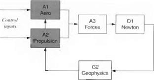
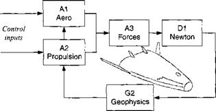
ROCKET3 is a derivative of GHAME3. Figure 8.18 shows the module structure. Only the shaded Modules A1 and A2 are different. I will be very brief in my description. After having thoroughly explored the GHAME3 model, you should have no problem deciphering the FORTRAN code of ROCKET3.

ROCKET3: Three-Stage Rocket Simulation

Fig. 8.16 GHAME3 hypersonic vehicle trajectory.

The aerodynamics is modeled by simple polynomials in Mach number with linear dependency on angle of attack. The thrust for each stage is calculated from Eq. (8.24), then substituted into Eq. (8.25). Because we are dealing with liquid rockets, a throttle factor thr is inserted:

Ели = hvmgo thr + (psL – рмдК (8.32)

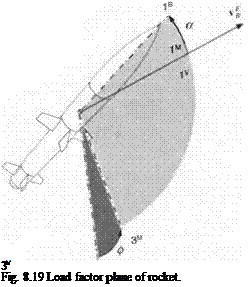
You may be puzzled by the fact that the A3 Module remains unchanged. For the earlier planar symmetry case, the airplane executes a perfect bank maneuver, maintaining its plane of symmetry in the load factor plane. Now look at Fig. 8.19. Conventional rockets and missiles, having tetragonal symmetry, do not bank to turn, but can generate a maneuver by pitch and lateral force. As a result, however, the load factor plane forms a roll angle wrt the vertical plane. This roll angle is

ROCKET3: Three-Stage Rocket Simulation

Fig. 8.17 GHAME3 trajectory parameters.

Подпись: D1 " Newton
ROCKET3: Three-Stage Rocket Simulation

Fig. 8.18 ROCKET3 simulation modules.

the same as the bank angle of the aircraft. Therefore, ф serves as control input for both the aircraft and the missile, and we have no reason to change the A3 Module.

Подпись: 3V Fig. 8.19 Load factor plane of rocket.

You have become the master of simple point-mass, three-DoF simulations. I only carried through the Cartesian form of the equations of motion. It is left for you to implement the polar equations (see Problem 8.3). You should have an understand­ing of the standard atmosphere, gravitational attraction, and gravity acceleration. Simple drag polars model the aerodynamic forces, and the rate of change of linear momentum produces thrust. These elements of point-mass simulations are the basis for further development of more sophisticated five – and six-DoF models.

Problems

8.1 Three-stage rocket ascent to 300-km orbit. Task 1: Download the ROCKET3 simulation form the CADAC CD and run the test case INLAUNCH. ASC. Using CADAC-KPLOT, plot altitude, geographic and inertial speed, Mach number, dynamic pressure, heading, and flight-path angles vs time. Has the rocket reached orbital conditions?

Task 2: Now is your turn to lift the rocket to a 300-km near-circular orbit by scheduling angle of attack. Build the input file IN300.ASC. Can you achieve or­bital conditions? Again plot altitude, geographic and inertial speed, Mach number, dynamic pressure, heading and flight-path angles, and angle of attack vs time.

Task 3: Summarize your findings in a brief ROCKET3 Trajectory Report. Include all plots and the input file IN300.ASC.

8.2 SSTO vehicle simulation. If you followed the CADAC Primer from the CADAC CD, you have already flown the GHAME3 simulation with the

INPUT. ASC file, but could not reach orbital conditions. With the rocket-propelled SSTO, launched from a Super Boeing 747, you can achieve a low-Earth orbit.

Task 1: Modify the A1 and A2 modules of the GHAME3 simulation, using the data SST03 from the CAD AC CD. The A1 and A2 modules are much simpler for the SSTO.

ROCKET3: Three-Stage Rocket Simulation

Task 2: Now, launch the SSTO from the Super B747 12 km above Cape Canaveral, Florida, horizontally in an easterly direction with |uf | = 253 m/s. Building the input file INCAPE. ASC with the following control commands for the ascent:

r, s

a, deg

thr

<200

22.93

0.9

200-400

5.73

0.9

>400

5.73

0.5

At burn-out what are the values of |uf |, /, у, І, X, hi What is the inertial speed [u^]7, Kl? (Solution: t = 658 s, |uf| = 7442 m/s, / = 102°, у =6.4°, / = — 1.074 rad, A = 0.461 rad, and h = 106 km.)

Task 3: Next, repeat Task 2 for Vandenberg, California, but launch in a westerly direction. Build the input file INVAN. ASC and provide the same output.

Task 4: Repeat Tasks 2 and 3 for a nonrotating Earth.

Task 5: Write a summary report SST03 Ascent Trajectories. Provide all burn­out conditions in one summary table. Include the input files. For Task 2 plot altitude, geographical and inertial speeds, flight-path angles, and fuel mass vs time.

8.3 SST03 simulation with polar equations of motion. In Sec. 8.1.2 I derived the equations of motion with the Earth as reference, while maintaining J2000 as the inertial frame. These equations should lead to the same results as the Cartesian formulation of Problem 8.2.

Task 1: Review Sec. 8.1.2 and code a new Module D1 with the polar equations of motion, Eqs. (8.11) and (8.12). Keep all other modules of the SST03 unchanged. Verify that all changes are made correctly by using MKHEAD3.EXE.

Task 2: Use the input file INCAP. ASC from Problem 8.2 and run your polar SSTO3 simulations. The endpoint parameters should agree with less than 1 % error. Plot the Coriolis and centrifugal accelerations and compare them to the gravita­tional term. Plot these three variables vs time. What conclusions do you draw?

Task 3: Summarize your work in the SSTO Polar Simulation Report. Document your D1 Module, show your plots, and discuss your findings.

GHAME3: Hypersonic Vehicle Simulation

Thanks to NASA’s forethought, we have a complete data package of a hypersonic vehicle, called Generic Hypersonic Aerodynamic Model Example (GHAME). You will encounter it again in Chapter 10 as an example of a complex six-DoF simu­lation.

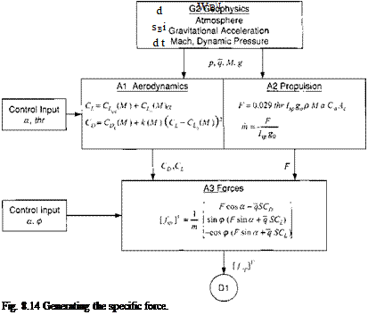
The simple three-DoF structure of the CADAC GHAME3 simulation is shown in Fig. 8.8. The three external force modules, gravity (G2), aerodynamics (Al), and propulsion (A2) are combined in the A3 Force Module to serve Newton’s law (Dl). In addition, the Geophysics Module G2 provides also atmospheric density pressure and sonic speed.

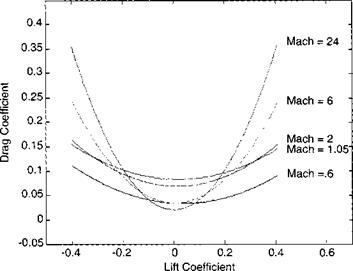
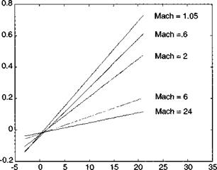
8.3.1.1 Aerodynamics. For the purpose of this chapter, I have reduced the aerodynamics of the six-DoF GHAME model to an offset parabolic drag polar by curve fitting the full data set (see Fig. 8.9). Because the lift coefficient CL is the independent variable, automatic plotting programs place it on the abscissa and use the drag coefficient as ordinate. Notice the change of the drag polar with Mach number. The minimum zero-lift drag Cd0 occurs at subsonic and hypersonic speeds and peaks near Mach 1. The lift-over-drag ratio, indicated by the flatness of the parabola, decreases with increasing Mach number. Do you see the slight bias of the parabola centerlines toward positive lift values? This shift is more evident in the lift slopes of Fig. 8.10. The zero-lift points occur between 1-2 deg angle of attack at all Mach numbers. Both sets of curves are implemented as tables in the Al Module.

8.3.1.2 Propulsion. The combined-cycle engine of GHAME is programmed in Module A2. From Eq. (8.26)

GHAME3: Hypersonic Vehicle Simulation

Fig. 8.9 GHAME parabolic drag polar.


Подпись: Lift Coefficient

Alpha – deg


Fig. 8.10 GHAME lift slopes.


GHAME3: Hypersonic Vehicle Simulation

GHAME3: Hypersonic Vehicle Simulation

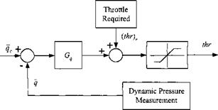
Fig. 8.11 Autothrottle for constant dynamic pressure control.


we calculate thrust F from two tables, specific impulse /sp(A/, thr) and capture – area coefficient Ca(M, a). To keep track of the remaining fuel, the fuel rate is monitored based on Eq. (8.24)

Подпись: (8.28)F x thr m =

Isp8o

and integrated to provide the expended fuel mass.

One of the crucial factors of a hypersonic vehicle is the optimum throttle set­ting for best climb at minimum heating. An ascent with constant dynamic pressure approximates these requirements. Thus, we incorporate an automatic throttle feed­back loop into the propulsion module that maintains constant dynamic pressure and call it autothrottle. Figure 8.11 shows the control loop. Measured dynamic pressure q is compared with the desired input qc, processed through a gain Gg, and summed with the required throttle setting (thr)r overcoming the drag force. After limiting, the throttle setting for the thrust of the engine is obtained.

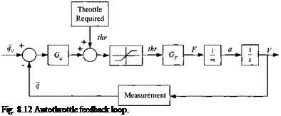
Подпись: Fig. 8.12 Autothrottle feedback loop.

To synthesize the autothrottle gain Gq, we complete the control loop as shown in Fig. 8.12. The thrust F from the engine with throttle setting thr accelerates the vehicle and, after integration, provides the velocity V that determines the dynamic pressure q.

Several steps determine the gain Gq. First, calculate the required thrust Fr by setting it equal to the drag, projected into the body Is axis by the angle of attack a

Подпись: Fr =CDS _

—— 4c

cos a

With Eq. (8.27) we calculate the required throttle setting

Подпись: (thr), =Fr

0.029 IspgoPVCaAc

GHAME3: Hypersonic Vehicle Simulation Подпись: = 0.029IspgopVCaAc Подпись: (8.29)

The thrust gain is therefore

The autothrottle control loop is essentially a first-order lag transfer function

Подпись: T(s) =1

T„s + 1

GHAME3: Hypersonic Vehicle Simulation Подпись: (8.30)

with the autothrottle time constant

To determine the autothrottle gain, pick a reasonable time lag between the com­manded and achieved dynamic pressure and calculate the gain from

Подпись:2m 1 PVGf Tq

where m is the mass of the vehicle. Clearly, the control loop is always stable, just make sure to select a realistic time constant, possibly making the time constant dependent on air density.

8.3.1.3 Forces. The aerodynamic and propulsive forces are combined in Module A3, coordinated first in load factor and then in velocity axes, divided by vehicle mass, and sent to the D1 Module as specific force [/sp]v.

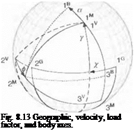
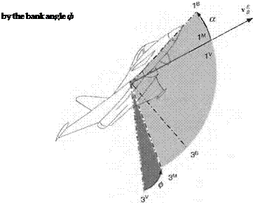
Refer back to Fig. 8.7 to visualize the geometry. To get a better understanding of the angles and coordinate axes, Fig. 8.13 displays all of the relevant information. It shows the heading and flight-path angles x and y, the bank angle ф, and the angle of attack a. These angles reflect the transformation sequence

jg (a jM jv У’* jG

Now we combine it with the thrust force F from Eq. (8.26):

Подпись:

Подпись: Fig. 8.13 Geographic, velocity, load factor, and body axes.

F cos a — qSCD 0

—Esin o; — qSCi

Подпись: Ua.p]V GHAME3: Hypersonic Vehicle Simulation Подпись: F cos о — qSCD sin 0(F sin o; + qSCb) —cos0(Fsino; + qSCb)

and transform it to velocity coordinates

Given о; and ф as input, the so-called contact forces (nongravitational forces) can be evaluated and provided as specific force /sp to Newton’s equation in velocity coordinates

[/spr = – Ua, p]V

m

where m is the vehicle mass.

8.3.1.4 Specific force. We have arrived at a convenient situation to summa­rize the four Modules G2, Al, A2, and A3 (see Fig. 8.14). Given the aerodynamic and propulsive characteristics, the inputs а, ф, and thr produce the specific force that is sent to the D1 Module.

8.3.1.5 Newton’s law. For the equations of motion, let us go back to Eq. (8.4) and divide both sides by the vehicle mass m

GHAME3: Hypersonic Vehicle Simulation

and adjoin the position equations (8.5):

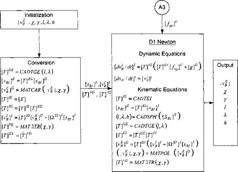
As convenient these equations are for integration, their interpretation is as difficult. Who wants to input trajectory parameters in inertial coordinates? We would much rather use geographic variables as input and output. Therefore, we need to develop code that transforms the input variables’ geographic speed |uf |, heading angle y„, flight-path angle у, longitude l, latitude X, and altitude h into inertial position [sbi]1 and velocity [r: д J7. Figure 8.15 shows the equations of motion and the conversion process.

Two types of utility subroutines are employed: the matrix utilities MATxxx and CADAC utilities CADxxx. You can find the MATxxx routines described in the C ADAC user documentation. These subroutines abide by FORTRAN call conven­tions. Writing them as [uf]G = MATCAR(Vg I, x. y) emphasizes the input/output relationship, but they are coded actually as CALL MATCAR ([u|]G, |uf |, x, y). There are three CADxxx subroutines appended to the D1 Module. CADTEI produces [T]EI, CADTGE calculates the transformation matrix Eq. (3.13), and

GHAME3: Hypersonic Vehicle Simulation

Fig. 8.15 Calculating the trajectory parameters.

CADSPH is the inverse transaction. If you are wondering how to get [sB/]G, re­member that its third coordinate is just the distance to the center of the Earth [Wif = Іo 0-(R9 + h)l

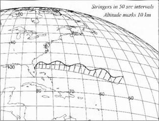
Now it is your turn to make this hypersonic vehicle soar into the stratosphere. Review the MODULE. FOR code, the INPUT. ASC and HEAD. ASC files; compile, link, and run the test case. It should produce an output that looks like the traces in Figs. 8.16 and 8.17.1 produced both figures with the CAD AC Studio plot programs KPLOT/2DIM and KPLOT/GLOBE. As you see from the weaving trajectory, cruising at constant angle of attack does not deliver a constant altitude trajectory.

Now change the input parameters and observe a variety of trajectories. Get a feel for the sensitivity of the vehicle to various modifications. Afterward do the SSTO project or turn to the ROCKET3 simulation.

Simulations

Building simulations is best learned by example. Study the venues, which others have trodden before you. For this reason I provide you with several simulations on the CADAC CD. You should supplement them with examples from your own work environment. Become a simulation glutton! In this section I document the two, three-DoF simulations GHAME3 and ROCKET3 that you find on the CADAC CD.

You may perceive my documentation lacking in detail. I challenge you to com­bine the source code, which is well interspersed with comments, with the following figures and derive the complete flow diagram of the two simulations on your own.

If this is your first exposure to CADAC, you have to lay some groundwork. First read the two volumes of CADAC Studio: Quick Start and Programmer’s Manual and print them out. You will need them as constant companions. Then run the test

Simulations

Fig. 8.8 GHAME3 simulation modules.

case TEST to make sure your computer is set up properly. Appendix В will launch you with the CADAC Primer.

Turbojet propulsion

The physical principle of airbreathing propul­sion again derives from Newton’s second law. However, the time rate of change of momentum is now based on the velocity increase of the airflow ma through the turbine. With V the flight velocity and Ve the exhaust velocity the thmst is (neglecting fuel mass and assuming ideal expansion)

F = ma(Ve – V)

The faster the exhaust velocity (turbine output) or the greater the airflow (high bypass), the greater the thrust F. In general, the thmst depends on several parameters:

F = /(Mach, altitude, power setting, angle of attack)

For some of our applications, we neglect the angle-of-attack dependency.

The specific fuel consumption (SFC) bp is an important indicator for the effi­ciency of the turbojet. It is defined by the ratio of fuel flow to thmst

Turbojet propulsion

The units of bp are usually given as kilograms/(deka-Newton hour), where dN can be written ION, and rhf is the fuel flow in kilograms/hour. The strange use of dN is justified by the approximate numerical equivalency of metric and English units

1 [kg/(dN h)] = 0.980665 [lbm/(lbf h)]

Typical values of SFC are between 1.0 to 0.3 kg/(dN h), with turbojets being less efficient than high-bypass turbofans.

8.2.4.3 Combine-cycle propulsion. In this section we focus on the high­speed regime of airbreathing engines. It is an area of vigorous research and devel­opment, spurred on by the National Aerospace Plane (NASP), the single-stage-to – orbit (SSTO) requirement, and various X vehicles. We are also motivated to look into high-speed propulsion because the GHAME3 and GHAME6 simulations use turbojet, ramjet, and scramjet engines to ascend through all Mach regimes into the stratosphere.

Turbojets and turbofans are particularly suited for the low-speed portions of the mission and have adequate performance up to Mach 3. The upper limit is imposed by the thermal constraints of their materials. Designs tend to have low overall pressure ratios and low rotor speeds at takeoff. With cryogenic fuels like liquid hydrogen, precooling can increase the maximum Mach-number regime to beyond 4, provided the engine operates above stoichiometric conditions.

Ramjets have no rotating machinery and start to operate above Mach 2. The internal flow remains subsonic, although they may perform up to Mach 6, limited by dissociation and material temperatures. Using hydrogen as a fuel and thus eliminating the need for flameholders can alleviate some of the material constraints.

Turboramjets combine turbojets and ramjets in wraparound or tandem designs. A high efficiency intake is combined with an ejector nozzle. It matches the full intake capture area demanded during transonic flight. The excess capture flow is passed down a duct, concentric with the engine, which also serves to bypass the turbomachinery in the ramjet mode. Turboramjets operate from static conditions at sea level up to Mach 6 at high altitudes.

Turborockets use hydrogen/oxygen combustors to produce the working fluid for the turbine. The combustion is fuel rich so that the turbine entry temperature is kept within the capability of uncooled materials. The excess hydrogen is burned in the fan stream air, with secondary hydrogen injected to produce an overall stoichiometric mixture. Fan materials limit the upper Mach number to about 4.

Scramjets are similar to ramjets, except that their combustion occurs at su­personic speeds. Although they can operate at lower speeds, they become more efficient than ramjets only above Mach 6.

The turboramjet/scramjet is a three-cycle variable inlet geometry design, capa­ble of providing thrust from static sea-level conditions to hypersonic atmospheric exit. NASA uses it for their GHAME concept. The breakpoints for the cycles are 1) turbojet from Mach 0 to Mach 2,2) ramjet until Mach 6, and 3) scramjet beyond.

The authors of the GHAME propulsion package13 apologize for the simplicity of their approach, but I find their model quite lucid. They start with the basic thrust equation (8.24) F = Isvmg0 i. e., thrust equals specific impulse times weight flow rate through the engine. Because we deal with airbreathers, the weight flow rate is essentially the amount of air sucked through the intake area Ac. Therefore, given the speed of the vehicle V =Ma and the air density p, the weight flow rate is

mg о = g0pMaAc

which assumes that the air enters the cowl uniformly. However, the intake flow of a turboramjet/scramjet engine is very intricate, influenced by engine cycle, Mach number, and angle of attack. This complexity is distilled into a capture – area coefficient Ca, which is dependent on Mach number and angle of attack. Subsonically, it starts with values near 1, drops to 0.2 in the transonic region, then rises slightly until the ramjet takes over at Mach 2. Thereafter, it increases beyond 1 and tops out under the scramjet cycle at about 5. As the angle of attack increases, the effective capture area grows, and the Ca value almost doubles at 21 deg. With this correction factor the effective weight flow rate is

mgo – gopMa Ca(M, a)Ac

The pilot controls the fuel flow and the variable intake by the throttle setting thr. Indirectly, the pilot adjusts the fuel/air ratio of the engine to the stoichiometric ratio, which equals 0.029 x thr, by adjusting thr between the values zero and two. The specific impulse /sp is a function of the engine cycle, the throttle setting, and Mach number. It increases with throttle setting and decreases with Mach number.

Now we have assembled all of the elements for the thrust equation (8.24):

F = 0.029 thr /sp(M, thr)g0pMa Ca(M, a)Ac (8.26)

As the vehicle takes off with full throttle, low Mach, and high angle of attack, its thrust is at a near maximum. During the climb-out, in the transonic region with decreasing a the effective capture area is significantly reduced so that the pilot will maintain max throttle until the ramjet regime is reached. Then the pilot begins to throttle back to conserve fuel.

You will be surprised and may be disappointed to learn that this is all I have to say about propulsion. If you have to build a propulsion simulation, you should assemble a team of experts that will model such effects as inlet flow, thermodynamics, combustion efficiency, exhaust, installed drag, and stall. You can then provide the aerodynamics, mass properties, and the simulation environment. Here, I emphasize a general treatment that enables you to build three-, five-, and six-DoF simulations quickly without resorting to specialists.

You will find examples throughout the family of CADAC simulations. ROCKET3 models liquid-fueled, three-stage rockets; GHAME3 and GHAME6 mimic the NASA combined-cycle engine; CRUISE5 and FALCON6 use simple subsonic tur­bojet models; and AIM5, SRAAM5, and SRAAM6 are propelled by solid rocket motors. We will turn now to the description of the two, three-DoF simulations GHAME3 and ROCKET3.

Rocket propulsion

The principle of rocket thrust goes back to the ancient Chinese and their brilliant firework displays. Then and now it is based on Newton’s second law, applied to the exhaust stream with the velocity c and the mass flow m (see Example 5.6):

F = me

Instead of providing the exhaust velocity, usually the specific impulse /sp is given. It is defined as the ratio of the impulse delivered, divided by the propellant weight consumed

Подпись: (8.23)FAt _ F mg0At mg„

where g0 is Earth’s gravity acceleration referenced to the fixed, standard value g0 = 9.80665 m/s2. Solving for F yields the alternate thrust equation

F = Ispthgo (8.24)

The exhaust velocity is therefore related to the specific impulse by c = Isvg0- Specific impulse provides an important characterization of the rocket engine and its propellant. Typical values are given in Table 8.1 for double-based solid propel­lants like nitrocellulose (NC) and nitroglycerin (NG) and liquid bipropellants like hydrazine (N2 H4) and oxygen (O2).

Table 8.1 Typical values for solid and liquid propellants

Propellant

Density, kg/m3

A P, s

Bum rate functional dependence

Solid

1700

250

f(p, rfuei, surface area)

Liquid

1200

350

/ (pump feeding)

The thrust of a missile is usually given at sea level. A correction has to be made for the thrust at altitude. Suppose FsL is the sea-level thrust; a term is added that corrects for the fact that the pressure at altitude pAt is less than the pressure at sea level psh – With the exhaust nozzle area Ae the thrust at altitude is

FAit = Fsl + (Psl — Раі)Ає (8.25)

For solid propellant the sea-level thrust is most likely given as a function of bum time and possibly of propellant temperature. A simple table look-up routine will suffice. If only specific impulse and propellant bum rate are known, Eq. (8.24) will provide the thrust. This equation also serves the liquid propellant rocket motor. You just need to include a multiplying factor that represents the throttle ratio (values between zero and one). To complete the propulsion model, the expended propellant is monitored for updating the vehicle’s mass.

Propulsion

Unless you are a glider enthusiast, you value propulsion as the means of keeping missiles and aircraft in the air. The thrust vector overcomes drag and gravity and maintains the speed necessary for lift generation. It is usually directed parallel to the vehicle’s centerline, although helicopters and the V-22 Osprey display their individuality by thrusting in other directions as well. For our simulations we deal only with body-fixed propulsion systems whose thrust vector is essentially in the positive direction of the body Is axis, possibly slanted by a fixed angle.

You will be surprised how far just basic physics will take us in modeling missile and aircraft propulsion. However, you should not bypass the solid foundations laid in the classic book by Zucrow7 and the excellent textbook by Cornelisse et al.8 Some recent and up-to-date compendiums were published by AIAA for missile propulsion,9 hypersonic airbreathers,10 and aircraft propulsion.11 Even the control book by Stevens and Lewis12 has some useful information on turbojet engine modeling.

Most missiles are rocket propelled with the oxidizer carried onboard. Some supersonic missiles use the oxygen of the air for combustion in their ramjet or scramjet propulsion units. The air is captured by the inlet, retarded and com­pressed, fuel is injected and ignited, and the mixture exhausted through the noz­zle. No rotary machinery is employed. Aircraft and cruise missiles, on the other hand, employ rotating compressors and turbine machinery for propulsion. Based on simple physics, I will derive the thrust equations for rockets, turbojets, and combined-cycle engines.

Newton’s second law will serve us well, both for missile and aircraft propulsion. In each case the time-rate-of-change of momentum generates the propulsive thrust. We first derive the thrust equation for rockets.

Parabolic Drag Polar

Modeling aerodynamic forces and moments of aerospace vehicles can be a formidable task. Multimillion-dollar wind-tunnel facilities have been built and supercomputers put to work to measure, calculate, and predict the flow phenomena. A mathematical framework must be found to express these data in a form that can be programmed for the computer. In Chapters 9 and 10 you will encounter models for missiles and aircraft at increasing levels of sophistication. For three- DoF simulations, we can confine ourselves to expressions that relate drag and lift by simple polynomials.

We go back to the latter part of the 19th century and find Otto Lilienthal exper­imenting with hang gliders. He took his hobby very seriously and is credited with relating lift and drag by what he called “die Flugpolare” (the drag polar). After his accidental death in 1896, the Wright brothers6 credited him in 1901 with laying the foundation of flight by experimentation.

The lift force L is normal to the velocity vector of the aircraft wrt the air and is contained in the plane of symmetry of the aircraft. The drag force D is parallel and in the opposite direction of the velocity vector. Nondimensional aerodynamic coefficients are formed from the dynamic pressure q and the reference area S (airplanes use wing area and missiles employ body cross section).

Lift coefficient:

Parabolic Drag Polar

Drag coefficient:

Parabolic Drag Polar

with q = (p/2)V2, p the air density, and V the speed of the aircraft relative to air. Both coefficients are assumed to be functions of the following parameters:

Cl, Cd = /{Mach, angle of attack, power on/off, shape}

Mach number, the ratio of vehicle velocity over sonic speed, can have a signifi­cant effect on the coefficients during the transonic and supersonic flight regimes. The main effector however is the angle of attack, which, with only small varia­tions, changes the lift coefficient decisively. Depending on the installation of the propulsion unit, the airflow around the wing or tail modifies the drag character­istics. Particularly for missiles with boost motors, the drag increases significantly during the coast phase. Naturally, the shape of the vehicle determines the overall aerodynamic performance, but the size of the vehicle has only a minor influence on the coefficients. This insensitivity to scale justifies much of the considerable wind-tunnel investments.

When drag data are plotted against lift, a near parabolic curve emerges for any given Mach number. What a break for the aerodynamicist! He can model the func­tional relationship by a second-order polynomial, called the parabolic drag polar.

CD = CDo+k(CL-CL()2 (8.18)

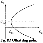
The parabola is shown in Fig. 8.4. Not surprisingly, drag is never zero even at zero lift. It has a minimum value of Co0, which may occur at a nonzero lift value C/ o. A parabolic drag polar thus shifted upward is called an offset polar. The factor к determines the drag increase caused by deviation from minimum drag and is referred to as the induced drag coefficient.

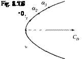
If the minimum drag occurs at zero lift, the function simplifies to a centered polar (see Fig. 8.5):

The drag polar is centered on the drag axis if the vehicle has two planes of symmetry—like a conventional missile—or if a wing with symmetrical airfoil is the dominant lifting surface. The parameter of the parabola is the angle of attack a. The higher the angle of attack is, the greater the lift and drag forces, up to the point when the flow starts to separate from the main lifting surface. Thereafter, lift breaks down, but drag keeps increasing, and the parabolic model has lost its usefulness.

The noninduced drag coefficient Сд> models such phenomena as surface fric­tion, profile drag, and supersonic wave drag. The second term represents the in­duced drag caused by lift. For vehicles that traverse through more than one Mach region—subsonic, transonic, supersonic, or hypersonic—the coefficients CDo, Cl0, Ci, к must be modeled as functions of Mach number.

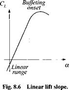
The drag polar presupposes that lift is given and drag is derived. In simulations, however, one prefers to specify the angle of attack as input rather than lift. A relationship must therefore be established between the lift coefficient and angle of attack. Fortunately, experimental evidence points to a linear relationship (see Fig. 8.6):

Подпись: (8.20)

Подпись: Fig. 8.4 Offset drag polar.

Cl = CLm + Ciaa

That linearity extends to the onset of flow separation, when lift brakes down rapidly. It is present over all Mach regimes. For vehicles with a centered drag polar, the lift slope goes through the origin, i. e., CiM = 0.

Parabolic Drag Polar

The parabolic drag polar is an aerodynamic model suitable for simple point – mass three-DoF simulations from subsonic to hypersonic flight regimes. Be careful,

Parabolic Drag Polar

however, and do not expect too much accuracy from the results. Imposing a second – order polynomial curve washes out minimum drag cups near the cruise conditions and, as already noted, does not account for the onset of buffeting. A parabola also assumes lift symmetry for positive and negative angles of attack—hardly the case for airplane wings with high-lift airfoils. Furthermore, we also neglected Reynolds-number dependency and skin-friction changes with altitude.

All of these shortcuts were taken to get you started with simple simulations. As you gather more data, you can abandon the parabolic fit in favor of higher-order polynomials or use tables to accurately model the functional relationship between the lift and drag coefficients. However, there are inherent restrictions that come with the point-mass approach.

One supposition is the neglect of the control surface effects on lift and drag. Their contribution could be included as so-called trimmed values, if we had a full force and moment model available for data reduction. However, in that fortunate case we may as well build a full six-DoF simulation.

Another assumption restricts the lateral maneuver to coordinated turns only, i. e., the aircraft banks without sideslipping. The same limitation applies to missiles, unless they possess rotational symmetry, in which case the lift and drag forces always lie in the load factor plane, irrespective of the body bank attitude. In effect, for both missiles and aircraft the drag polar applies to the aerodynamic forces in the load factor plane.

Figure 8.7 helps us to define the load factor plane. It coincides with the Is, 3s symmetry plane of the aircraft and contains the velocity vector v f of the aircraft wrt to Earth. The bank angle ф establishes the orientation of the load factor plane relative to the vertical plane, which contains the lv,3V axes (Iv coincides with vf). The angle of attack a positions the aircraft centerline above the velocity vector in the load factor plane. It is useful to introduce the load factor coordinate system. Its Iм axis is parallel and in the direction of the velocity vector vf and Iм coincides with 2s. In load factor coordinates the resultant aerodynamic force possesses lift and drag as its two components:

[fa]M=qS[-CD 0 – CJ (8.21)

The transformation matrix of the load factor wrt velocity coordinates is determined
and the aerodynamic force in velocity coordinates is therefore

Подпись:

Parabolic Drag Polar Подпись: (8.22)

[.faY = [? ]MV[fa]M = qS

As expected, the drag force opposes the aircraft velocity directly, and the lift force, modulated by bank angle ф, generates the horizontal maneuver force С/ sin ф and the vertical force —Ci cos ф.

Modeling the aerodynamics of airplanes and missiles with a parabolic drag polar is a quick way to get preliminary performance estimates of new concepts when the database is still scant. Furthermore, this simple approach is also quite useful for mission-level simulations with their frugal trajectory models. There, the aircraft and missiles are well defined; but because of the large number of participating vehicles, their fly-out simulations must be kept artless.

So far, we have dealt with the gravitational and aerodynamic forces. To complete the right-hand side of Newton’s law, we must address the force that overcomes gravity and drag, namely thrust. I shall discuss rocket and airbreathing propulsion in a form not just suitable for three-DoF models, but also quite applicable to five – and six-DoF simulations.