Category Modeling and Simulation of Aerospace Vehicle Dynamics

Planar aircraft

9.2.1.2 In five-DoF simulations an aircraft, executing bank – to-turn maneuvers, is assumed to do so at zero sideslip angle. The lift and drag

Planar aircraft

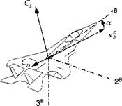
vectors lie in the load factor plane (see Fig. 9.5), and their aerodynamic tables are, therefore, only a function of the incidence angle a.

CL or Сц = f{M, a, power on/off}

A bank-to-tum autopilot provides this incidence angle a together with the bank angle фву – Because the symmetry plane coincides with the load factor plane, the transformation of the forces to body axes is like in Eq. (9.30) with the angle of attack a assuming the role of the total angle of attack a’

Подпись: (9.33)Ca — —Ci sina + Co cosa Сц = Ci cos a + Co sin a

When you read the newer literature,5 you will find the aerodynamic coefficient defined in the positive direction of the body axes, Cx and Cz■ They are in the opposite direction of Ca and Сц and are obtained from lift and drag coefficients by

Подпись: (9.34)Cx = Ci sina — Co cos a

Cz = —Cl cosa — Co sina

In either case, the aerodynamic force vector for Newton’s equation is

Подпись:Подпись: Ifaf = qS(9.35)

The trimmed aerodynamic tables of aircraft are usually built as functions of Mach and alpha. Several sets may be required for power on/off, or different configu­rations, like flaps in/out or gear in/out. Sometimes skin-friction corrections with altitude are also included.

The generic cruise missile simulation CADAC CRUISE5 can serve as an ex­ample. Its Cl and Cd tables are given as functions of Mach and angle of attack for three c. m. locations. With the turbojet engine providing continued thrust, we model only power-on drag. Let us now turn to the propulsive forces.

Tetragonal missiles

A tetragonal missile’s aerodynamics is only weakly dependent on the roll orientation of the body. For simple pseudo-five-DoF simulations, we neglected that effect altogether and are left only with the total incidence angle a’:

CL or Сд = f{M, a!, power on/off}

Подпись: / a Подпись: arccosfcosa cos fi}, Подпись: ф' = arctan Подпись: tan p sin a Подпись: (9.29)

If the missile executes skid-to-tum maneuvers, the autopilot provides a and f information, which is converted to aeroballistic incidence angles by Eq. (3.24):

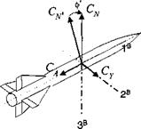
The lift vector is normal to the velocity vector in the load factor plane and is a function of a’. Many missile simulations require the forces to be expressed in body coordinates. We make the conversion in two steps. First, we transform lift and drag to normal force and axial force coefficients in aeroballistic wind coordinates through the angle a’

CA> = —Ci sin a’ + CD cos a’

Подпись: (9.30)CN> = Ci cos a’ + Сд sin a’

followed by the rotation through the angle ф’ to body fixed axes

CA = Ca’

Cy = — Cn> sin ф’ (9.31)

CN — CN> cos ф’

Let us pause and point out the difference between the aeroballistic ф’ of Fig. 9.4 and the bank angle фву of Fig. 9.3. Both are transformation angles about a 1 axis, but in the case of ф’ it is the body axis and for фву it is the velocity vector.

Подпись: t faf = qS Подпись: -CA Cy — CN Подпись: (9.32)

The aerodynamic force vector for Newton’s equations is now in body axes

Tetragonal missiles

Fig. 9.4 Transformation of aeroballistic wrt body axes.

Notice the negative directions of Ca and C v relative to the positive directions of the body axes. This convention is universally used for missiles and has its origin in the definition of positive lift and drag.

The aerodynamic tables of a typical air-to-air missile are a function of Mach, total angle of attack a’, and power on/off. For the sample simulation CAD AC SRAAM5, I also included skin-friction drag corrections caused by altitude changes. To im­prove the realism even more and recognizing the large change in mass properties during fly-out, I included the tables for three c. m. positions: fore, middle, and aft. They represent the changing trim drag caused by control deflections and are interpolated during thrusting.

In some applications you may be given the aerodynamic tables directly in nor­mal and axial force coefficients. If that is the case, you just bypass Eq. (9.30) and continue by converting the coefficients to body axes with the transformation Eq. (9.31).

We have defined the load factor plane as the plane containing the lift vector of a tetragonal skid-to-turn missile. Turning to planar aircraft, including cruise missiles, this arrangement is particularly advantageous.

Trimmed Aerodynamics

Aerodynamics simulates the forces and moments that shape the flight trajectory. To model these effects, the designer can resort to many references, computer pre­diction codes, and wind-tunnel data. A two-volume set of missile aerodynamics,1 updated in 1992, is a compendium of experimental and theoretical results, quite suitable for aerodynamic analysis. Semi-empirical computer codes, like Missile DATCOM,2 can make your life much easier and generate aerodynamic tables quickly, but at the expense of insight into the physical underpinning of the data. If you venture into the hypersonic flight regime, the industry standard is the Su­personic Hypersonic Arbitrary Body Program (S/HABP)3 for missiles and reentry vehicles. For aircraft, the old faithful DATCOM is still available4 and made more

palatable by Roskam.5 Of recent vintage are two books by Stevens and Lewis6 and Pamadi7 that treat aerodynamics as part of the control problem. Finally, let us not forget the venerable book by Etkin8 that served two generations of engineers.

In missile and aircraft simulations the emphasis is more on performance rather than on stability and control. The autopilot, controlling the vehicle, is already designed before building the simulation and hopefully performs well throughout the flight regime. Therefore, the focus is on tabular modeling of the forces and moments and not on stability derivatives. Angle of attack and Mach number are the primary independent variables, sometimes supplemented by sideslip angle and altitude dependency (skin-friction effects).

Pseudo-five-DoF simulations are content with simple aerodynamic representa­tions. Because we assume that the moments are always balanced and that the trim drag of the control surfaces is included in the overall drag table, we need only two tables: normal and axial forces, or alternatively, lift and drag forces. If power on/off influences the drag, we have to double up the drag table, and, if the c. m. shifts significantly during the flight, we have to interpolate between changing trim conditions.

We shall proceed from general aerodynamic principles. Aerodynamic forces and moments are, in general, dependent on the following parameters:

aero forces and moments

M, Re, a, p,a,$, p, q,r, Sp, Sq. Sr, shape, scale, power

^ flow incidence angles body rates control surface

characteristics and rates deflections

where the Mach number is velocity/sonic speed and the Reynolds number is inertia forces/frictional forces.

The forces and moments are nondimensionalized by the parameters q (dynamic pressure), S (reference area), and l (reference length). The resulting coefficients are independent of the scale of the vehicle. If a missile flies a steady course, exhibiting only small perturbations, the dependence on the unsteady parameters a, 0, p, q, r may be neglected. For the trimmed approximation the moments are balanced, and their net effect is zero. Thus, only the lift and drag coefficients remain nonzero. With the effects of the trimmed control surface deflections implicitly included, the lift and drag coefficients are the following.

Подпись: CL Подпись: L qS

Lift coefficient:

Подпись: CD Подпись: D qS

Drag coefficient:

where L and D are the lift and drag forces, respectively. Their dependencies are reduced to

The Reynolds number primarily expresses the dependency of the size of the vehicle and skin friction as a function of altitude. With size and shape of a particular vehicle fixed and altitude dependency neglected, the coefficients simplify further:

CL or CD — f{M, a, power on/off}

Now let us treat skid-to-tum missiles and bank-to turn aircraft separately. By the way, I am using the term missile and aircraft somewhat loosely. A short-range air – to-air missile most likely will have tetragonal symmetry (configuration replicates every 90-deg rotation) and execute skid-to-tum maneuvers; but a cruise missile or a hypersonic vehicle, with planar symmetry, behaves like a bank-to-tum aircraft.

Subsystem Models

For a missile or aircraft to fly effectively, many components must work together harmoniously. Just to name the most important ones: airframe, propulsion, controls, autopilot, sensors, guidance, navigation, and, in the case of a manned aircraft, the pilot. As we build a simulation, these subsystems must be modeled mathematically or included as hardware. In a flight simulator the pilot has the privilege to represent himself.

The shape of the airframe determines the aerodynamic forces and moments, and its structure determines the mass properties and deflections under loads. For our simplified pseudo-five-DoF approach we assume that the airframe is rigid. As mentioned earlier, the moments are balanced, and the drag as a result of steady – state control deflections is included in the aerodynamic forces. We model the aerodynamics using the so-called trimmed force approach.

Propulsion can be delivered by a simple rocket, a turbojet, a ramjet, or some other exotic device. It provides the force that overcomes drag and gravity and accelerates the vehicle. We simplify its features by employing tables for thrust and specific fuel consumption and introduce first-order lags for delays in the system.

In pseudo-five-DoF simulations, because of the treatment of the aerodynamics, controls are not modeled explicitly. What a simplification! Actuators need not be included, and you can forget about hinge moments. However, we give up the opportunity to study the dynamics of the controls and the effect of saturation of the control rates and deflections.

The stability and controllability of the vehicle are governed by the autopilot. The outer-loop feedback variable categorizes the type of autopilot. We distinguish between rate, acceleration, altitude, bank, flight path, heading, and incidence angle hold autopilots. Make sure, however, that for any type of autopilot, the incidence angle and its rate are computed and provided for the kinematic calculations (see Sec. 9.1). The autopilots are simplified models of the control-loop dynamics, and their responses simulate the vehicle’s attitude dynamics.

Sensors measure the states of the vehicle wrt other frames, like inertial, Earth, body, or target frames. They may be part of the air data system, inertial navigation system, autopilot, propulsion, landing, or targeting systems. Those with high band­width, like gyros and accelerometers, are modeled by gains without dynamics, and their output is corrupted by noise. Gimbaled homing seekers, on the other hand, exhibit transients near the autopilot bandwidth and should, therefore, be modeled dynamically, although for simple applications we also use kinematic seekers.

The smarts of a missile reside in its guidance laws. Given the state of the missile relative to the target, it sends the steering commands to the autopilot for intercept. We distinguish between pursuit, proportional, line, parabolic, and arc guidance. Guidance occupies the outermost control loop of the vehicle. In pseudo – five-DoF simulations, with the autopilot providing the vehicle response, this loop may be modeled with sufficient detail to be representative of six-DoF performance. Experience has shown that you could design the guidance loop initially in five-DoF and later include it in your full six-DoF simulation without modifications.

Finally, the navigation subsystem furnishes the vehicle with its position and velocity relative to the inertial or geographic frames. The core is the IMU with its accelerometers and gyros. Once their measurements are converted into navigation information, it becomes the INS. Errors in the measurements and computations corrupt the navigation solution. Therefore, navigation aids are employed to update the INS. Loran, Tacan, GPS or just overflight of a landmark can provide the external stimuli. Uncertainties are modeled by the INS error equations and by the noisy updates and filter dynamics.

Equations of Motion over Flat Earth

As you may have suspected all along, Earth is flat, at least for many engineers who develop simulations for aircraft and short-range missiles. They make Earth

the inertial frame and unwrap the curved longitude and latitude grid into a local plane tangential to Earth near liftoff. What a helpful assumption! It eliminates several coordinate transformations, simplifies the calculation of the body rates, and eliminates the distinction between inertial and geographic velocity.

If in Chapter 5, Eq. (5.25), the terms of Coriolis and transport acceleration are neglected, we obtain a form of Newton’s second law that assumes the Earth frame E is the inertial frame. We replace in Eq. (9.4) the inertial reference frame / by E and reinterpret the inertial velocity frame U as the geographic velocity frame V. The Hat-Earth equations of motions are then

[Dvveb][2] + [fiv£]v[uf]v = ^([fa, Plv + [ЛИ (9.20)

Подпись: [DV4]V = Подпись: d df Подпись: 0 0 Подпись: s[V 0 0]

with [vf ]v = [V 0 0], the geographic velocity of the c. m. wrt Earth expressed in geographic velocity coordinates, and [S1VEY the skew-symmetric equivalent of the angular velocity [ojve]v of the geographic velocity frame wrt Earth. The rotational time derivative is simply

On the right-hand side of (9.20), we must convert [fa, P]v = [f]BV[fa, p]B because the aeropropulsive forces are usually given in body coordinates. The gravity force is expressed best in local geographic coordinates, which for the round-Earth case were designated by ]G. With the flat-Earth assumption they are renamed local – level coordinates with the label ]L. Finally, we calculate the gravity force from [fg]v — [T]VL[fg]L with [fg]L = mB[0 0 g] and g the gravity acceleration.

Before Eq. (9.20) can be programmed, we have to convert the kinematic re­lationships to the flat-Earth case. We need the transformations [T]BV, T]VL, and [T]BL the angular velocity vectors [<yV£]> [caBV], and [шВЕ].

The transformation matrix [ T ]VL of the velocity wrt the local-level coordinates derives directly from Eq. (9.5). Just replace the angles фщ, вщ by the geographic heading angle фУь and flight-path angle 6Vi both referenced to the local-level coordinate axes. Alas, we are back on familiar ground. The obscure фщ, вщ angles have become the tried and true heading and flight-path angles on the Earth, which we called in Chapter 3 x and у, but prefer to designate here фг and Bvl – Figure 9.1 still applies with these changes, and Eq. (9.5) becomes cos 6VL cos фуі cos 6Vl sin фур — sin

Подпись: [T]VL —Подпись: (9-21)— sini/fyi COS фуі 0

sin 6Vi cos фуь sin Bvl sin фуі cos Bvi

The incidence angle transformation matrix [T]vv is retained for both the skid-to – turn and bank-to-turn vehicles. They are given by Eqs. (9.8) and (9.11), respec­tively. The direction cosine matrix [T]BL of body wrt local-level coordinates is the composition of

Now we convert the angular velocity vectors to the Hat-Earth case. The angular velocity coVEv of the velocity frame wrt the Earth frame and expressed in the velocity coordinates is obtained from Eq. (9.7) by redefining the inertial frame I to become the Earth frame E and the angles фщ, Ощ to change to фуь, 6yB:


-фуі smeVL

6vL

tvL COS 0VL


VE-,V


(9.23)


The incidence angular rates are transcribed from Eq. (9.10) for skid-to-tum missiles


$ sin a a

-$ cos a


[coBV]B =


(9.24)


and for bank-to-tum aircraft from Eq. (9.13)


(j>BV cos a
a

4>BV sin a


Equations of Motion over Flat Earth

(9.25)


Equations of Motion over Flat Earth

Equations of Motion over Flat Earth Equations of Motion over Flat Earth Equations of Motion over Flat Earth

фВу is the bank angle of the normal load factor plane rotated about the [vB ] vector from the vertical plane. Finally, the body rates [coBE] are the vectorial addition

in body axes

[wBE]B = [coBV]B + [T]bv[cove]v (9.26)

Notice how much simpler the calculation of the body rates is with the Hat-Earth as­sumption than for the round rotating Earth, Eq. (9.17). The simplification occurred because geographic and inertial velocities are undistinguishable. The kinematic conversions are now complete!

For programming, the left-hand side of the dynamic equations, Eq. (9.20), must be expressed in component form. We go back to the round-Earth component equa­tions, Eq. (9.19), and modify them for the Hat-Earth case:

Подпись:= [T]BV-^[fa, Pf + YT]VL^-[fg]L (9.27)

mB mB V

Let us expand the right-hand side of Eq. (9.27). The aerodynamic and propulsive term can be expressed in velocity coordinates directly. Lift and drag are referred to these coordinates, and thrust, usually parallel to the 1й axis, is projected by the angle of attack into the 1v axis. With these conventions we can adopt the three – DoF aerodynamic model of Sec. 8.2.3 to five-DoF simulations. From Fig. 8.14, A3 Forces, we borrow the formulation of the specific force:

Подпись:F cosa — qSCp
sin<t>Bv{F sina + qSCi)

—cos фву(Р sin a: +qSCL)

where F is the thrust, q the dynamic pressure, and S the aerodynamic reference area. In five-DoF simulations the lift and drag coefficients may now be more complicated functions of Mach and a than the simple parabolic flight polars of Chapter 8. More will be said about this subject in Sec. 9.2.1.

The gravity term of Eq. (9.27) is multiplied by the transformation matrix of Eq. (9.21). Combining the right-hand components with the left-hand side of Eq. (9.27) yields

V

1

III ^

F cosa — qSCo

-sin вуї

fVLV cos eVL

sin фву (F sina + qSCb)

+ g

0

1

1

s

1

—cos sina + qSCL)

COS вуї

(9.28)

Before you program these equations, clear the left-hand side of anything but the state variable derivatives V, ф v/ , and вуї,. You have three first-order differential equations with angle of attack a and bank angle фву as input. How this input is generated is the subject of the following sections.

Equations of Motion over Round Rotating Earth

Returning to Eq. (9.4), we multiply out the matrices on the left-hand side and express on the right side the aerodynamic/propulsive forces in body coordinates and the gravitational force in geographic coordinates:

Подпись: U фши cos Bui -вши = lT]BU^[fa, P]B + [T]UG^[fgf (9.19) ma ma

U is an abbreviation for d/df|i>g|, [T]BU is given by Eq. (9.15), and jT]^0 by Eq. (9.14). These are three first-order nonlinear differential equations with the states U, ij/ui, Oui – Solving for the state derivatives, we discover that in the second equation U cos вщ appears in the denominator. Therefore, these equations cannot be solved if U — 0 or вш = ±90 deg, which we avoid by programming around it. The designation specific force [/sp]B is assigned to the term [fa. P]B/mB, although it has the units of acceleration. (Remember: accelerometers measure specific force.) The gravitational term is simply

Подпись:= [g]G =

We have succeeded in expressing the equations of motion in matrix form. They are now ready for programming.

More Kinematics

Let us take stock of the progress we have made since laying out our require­ments toward expressing Eq. (9.4) in component form. Equation (9.5) provides the transformation matrix [T]ul, and Eqs. (9.8) and (9.11) deliver [T]B for the skid-to-turn missile and bank-to-tum aircraft, respectively. We build [T]UG from

[T]UG = [T]U,[T]GI (9.14)

with [T]GI, the transformation matrix of the geographic wrt inertial coordinates, given by the longitude and latitude angles (see Chapter 3).

To come to grips with the [ TBU transformation matrix, we string it out

[T]BU = [T]BV[T]VG[T]UG (9.15)

The challenge is to calculate [T]VG, the TM of the geographic velocity wrt geo­graphic coordinates. This will take several steps. We first calculate the geographic velocity v’l from the definition of the inertial velocity vf using the inertial posi­tion of the vehicle s Bi and the Euler transformation

vf = D! sBi = DesBi + ftE1sBi = vf + nE! sBi

Solve for vf and express it in geographic coordinates

[,f f = mYK]7 – [я£/] W)

From [uf]G we calculate the geographic heading and flight-path angles jrvc and 6vg, recognizing the fact that they are the polar angles of the velocity vector in geographic axes (CADAC utility MATPOL). Finally, from these angles we obtain [T]v’c (CADAC utility MAT2TR). We are now able to calculate Eq. (9.15).

In a moment we also will need

which we construct from Eqs. (9.15) and (9.5).

Back to Eq. (9.4), the angular velocity [Q. UI]U or its vector counterpart [ыи1]и is given by Eq. (9.7). Furthermore, we also need the body rates шв,]в for various modeling tasks. We build them up from

[o)B!]B = [шву]в + [a)VU]B + [coUI]B (9.17)

[шви]в is given by Eq. (9.10) for skid-to-turn missiles and by Eq. (9.13) for bank – to-turn aircraft. The second term [covu]B is the angular velocity vector of the geographic velocity frame wrt the inertial velocity frame. These two frames differ by the Earth’s angular velocity coEI. Expressed in inertial coordinates

Подпись: 0 0 [CO™]1 = [oF]1 =

Using Eqs. (9.16), (9.6), and (9.15), we can calculate the body rates

[(‘a)b,]b = [coBV]B + [T]BI[(oEI]’ + [T]BV[coul]u (9.18)

Rejoice! Our kinematic construction set is complete, and we can turn to the more profitable task of formulating the equations of motions.

Bank-to-turn incidence angles and rates

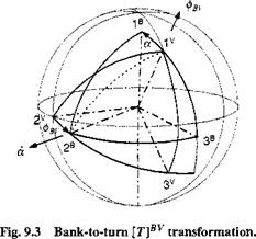
9.1.2.3 Now we use two dif­ferent incidence angles. The included angle between the geographic velocity vector v f and the first unit vector of the body b i is the total angle of attack a (we maintain the same symbol as in the skid-to-turn case). It is contained in the lB, 3B vertical body plane, which is also called the normal load factor plane. The banking of this plane from the vertical plane lv,3V is designated by the bank angle фву (see Fig. 9.3). Distinguish carefully between the Euler roll angle фвс (body axes, see Chapter 3), the aerodynamic roll angle ф’ (aeroballistic axes, see Chapter 3), and our bank angle фВу (velocity axes).

The body axes ]B and the geographic velocity axes ]v are defined as before. However, the total angle of attack a lies now in the normal load factor plane, and the bank angle фв/ is obtained by rotating about the velocity vector v f, which is parallel to the base vector v i. The sequence of rotation is

Подпись: [T]BV Подпись: cos a sin a sin 0 COS фву sin a — cos a sin фву Подпись: —sin ot cos фву sin фву cos a cos фВу Подпись: (9.11)

and the transformation matrix of the body coordinates wrt the geographic velocity coordinates is

Here you can see the difference between the aeroballistic and bank angle treat­ments. Compare this transformation with the transformation matrix of the body wrt the aeroballistic wind coordinates [T]BV, Eq. (3.19) of Chapter 3, and you will recognize the difference.

The angular velocity of the body frame wrt the geographic velocity frame is derived from Fig. 9.3. Combining the incidence rates with their respective unit vectors and adding them vectorially yields

шву = 4>BVv+ab2 (9.12)

Expressed in body coordinates

[coBV]B = 4>BV[T}BV[Vl]v + a[b2]B and evaluated with the help of Eq. (9.11),

Подпись: [c/YПодпись:фВуcos a a

<pBV sin a

The angular velocity of the body frame wrt the geographic velocity frame is a function of the incidence angular rates and the angle of attack (redefined) but not of the bank angle. Both the angular rates and the angle of attack are given by the transfer functions of the autopilot.

Skid-to-tum incidence angles and rates. I

n the skid-to-turn case the angle of attack and sideslip angles determine the deviation of the velocity vector from the centerline of the vehicle. However, we must use the velocity vector of the vehicle relative to the air mass instead of the inertial frame because incidence angles are used in conjunction with the aerodynamics of the vehicle. We name

a


Fig. 9.2 Skid-to-tum [TBV transformation.


Skid-to-tum incidence angles and rates. I

this velocity frame V and the associated geographic velocity vector v§, i. e„ the velocity of the c. m. of the vehicle В wrt the Earth E.

The body axes ]® are associated with the body frame B, and their positive direction is defined as follows: 1® is the body centerline, 2® the right wing, and 3® points down.

The geographic velocity axes ]v are associated with the geographic velocity frame V and given by 1v as the velocity vector, 2V in 1G, 2° horizontal plane.

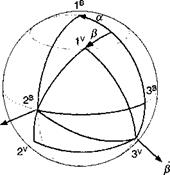
The incidence angles are a as the angle of attack and /3 as the sideslip angle. Refer to Fig. 9.2 and compare it to Fig. 3.17 in Chapter 3 to confirm that the incidence angles are the same. The sequence of transformation is ]®<—]•<— ]v. Notice the negative sense of the transformation of the sideslip angle. The transformation matrix between the body and geographic velocity coordinates is

cos a cos P —cos a sin —sin a

Подпись: (9.8)[T]BV = sin/1 cos /3 0

sin a cos /3 — sin a sin /3 cos a

It is the same for our pseudo-five-DoF treatment as for the full-up six-DoF simu­lations (see Chapter 10).

Skid-to-tum incidence angles and rates. I Подпись: (9.9)

The angular velocity of the body frame wrt the geographic velocity frame is derived from Fig. 9.2. Combining the incidence rates with their respective unit vectors and adding them vectorially yields

Expressed in body coordinates

[0)®T =$[T]BV[U3]V +a[b2]B

Skid-to-tum incidence angles and rates. I

and evaluated with the help of Eq. (9.8)

Skid-to-tum incidence angles and rates. I

The angular velocity of the body frame wrt the geographic velocity frame is a function of the incidence angular rates and the angle of attack, but not of the sideslip angle. Both the angular rates and the angle of attack are given by the transfer functions of the autopilot.

Coordinate Transformation Matrices and Angular Rates

At this point I advise you to review Chapter 3. It will lubricate your understanding of the abbreviated derivations that follow. Besides the transformations, I will also deal with the angular velocity vectors u>BU and u>UI because they can be derived directly from our orange peel diagrams.

9.1.2.1

Подпись: Fig. 9.1 [T]GI transformation.

Transformation matrix of velocity wrt inertial coordinates. The inertial coordinates are defined in Chapter 3. Figure 9.1 turns the world upside down so that the heading and flight-path angles take their conventional orientation, and we can readily switch later to flat-Earth approximation. However, jzщ and вщ are at this point not the usual heading and flight-path angles. They are referenced to the Earth-centered inertial (J2000) coordinate system for the sole purpose of for­mulating Newton’s equations wrt the inertial velocity frame. We call them inertial heading and flight-path angles to distinguish them from the standard heading and flight-path angles, which we will derive later.

The inertial coordinate system ]7 is associated with the inertial frame I. Its axes are defined as follows: l7 is the direction of vernal equinox, and 37 is the Earth rotation axis. The inertial velocity axes ]u are associated with the inertial velocity frame and given by the following: u is the direction of velocity vector, 2U is in l7, 27 plane; фщ is the inertial heading angle; and вщ is the flight-path angle. The standard sequence of transformation is

Подпись: [Г]777 = Подпись: COS вщ COS frui -sin fVI sin вщ COS xfrui Подпись: COS вщ sin jfui COS fui sin вщ sin 1jfui Подпись: -sin ви I 0 COS вщ Подпись: (9.5)

It is similar to the transformation sequence in Sec. 3.2.2.6 of the flight-path coordi­nates wrt geographic coordinates. Only here we start with the inertial coordinates ]7 and end up with the velocity coordinates ]L. The transformation matrix is

Let us take the opportunity and derive the angular velocity of the velocity frame wrt the inertial frame. In Fig. 9.1 the angular rates of the inertial heading and flight-path angles are indicated. Combining them with their respective unit vectors and adding them vectorially yields

U)UI = фщІз + вщІІ2 (9.6)

Later we will need their component form in the velocity coordinate system. So let us express the inertial unit vector in its preferred coordinate system ]7 and convert it to the Ju coordinates

[coUIf = фщ[Т]шЦз]! +вщШи

and multiplied out with the help of Eq. (9.5)

Подпись:Подпись: (9.7)Ф UI sin вщ вщ

Ф UI C0S віл

The angular velocity of the inertial velocity frame wrt the inertial frame is a function of angular rates and the flight-path angle but not the heading angle. Both the angular rates and the flight-path angle are obtained by solving the equations of motion.

We now turn to the incidence angle transformation matrices and their angular rates. As already discussed, we must distinguish between the skid-to-tum and the bank-to-turn cases for missiles and aircraft, respectively.