Category Modeling and Simulation of Aerospace Vehicle Dynamics

Gravitational Attraction

What is gravity? Nobody knows for sure; we only can measure its effects. Long ago the ancient Greeks wrote about it and speculated about its origin. For us engineers, Isaac Newton has provided all we have to know. His inverse square law says it succinctly: The gravitational pull between two bodies is proportional to the product of their masses and inversely proportional to the square of their distance. Suppose two particles with mass да and да,- are separated by r, then the force of attraction F is, with G as the proportionality constant,

Gravitational Attraction(8.15)

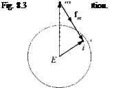
If the body consists of a collection of particles да, , г = 1, 2, 3, …, then the test mass m is affected by the attraction of each particle. As we place the test mass at different locations, we can calculate the gravitational field by measuring the force and dividing it by the test mass да. Introduce the displacement vectors s TE of the test mass T wrt a reference point E of the massive body E, and the displacement vector SiE of a particle і wrt the same reference point E (see Fig. 8.3). The gravitational field is described by

Gravitational Attraction

Gravitational Attraction

(8.16)

Gravitational Attraction

where the force vector of the test mass fm has the same direction as the dis­placement vector s, T = SiE — sTe■ The gravitational field is the gradient of the gravitational potential S7U{ste] = gf-S’/r}- The gravitational potential itself de­fines the equipotential surfaces

A unit test mass has the same potential energy anywhere on an equipotential surface against the collection of particles m,-, і = 1, 2, 3,… .

The equipotential surface of the Earth is called the geoid, an irregularly shaped envelope. An important approximation of the geoid is the geocentric equipotential ellipsoid of revolution. Its most recently updated dimensions are given in the Defense Mapping Agency’s “U. S. World Geodetic System 1984 (WGS84)”.5 I have more to say about it in Chapter 10, when we derive the equations of motion for an elliptical Earth.

Gravitational Attraction

In this chapter we confine ourselves to the approximation of a spherical Earth, defined by a gravitational field with spherical equipotential surfaces. Its gravita­tional field simplifies after having summed Eq. (8.16) over the homogenous sphere

Suppose the test mass is a missile T with mass m. The gravitational acceleration on the missiles is in the opposite direction of the displacement vector. v EE of the missile wrt the center of Earth E, and the magnitude of the gravitational force is with |®ге| = r

Gravitational Attraction(8.17)

The product GM is an important constant for planet Earth with the value GM = 3.986005 x 10¹⁴ m3/s2.

Living on Earth subjects us to a gravitational acceleration of g = 9.82023 m/s2. Yet we do not feel the full brunt of Earth’s pull because it is opposed by the centrifugal force of our “merry-go-round.” Both accelerations vectorially added results in the so-called gravity acceleration

Подпись: І®7ЕІЕй{5те) =g~ nE, nE, sTE = —GM r—- Ue, Ueiste

with Earth’s angular rate of coEJ = 7.292115 x H)~5 rad/s. The value of the gravity acceleration depends on your latitude and altitude. At sea level (mean radius of Earth — 6,371,005 m) standing on the equator, gg = 9.7864 m/s2, and at 45° latitude gg = 9.8033 m/s2. The accepted standard average value Ls g — 9.8066 m/s2. Come, join me at the equator, life is lighter there! Before you leave however, make sure you understand the difference between gravitational and gravity acceleration.

Subsystem Models

8.2.1 Atmosphere

Without atmosphere, life on Earth would be miserable. I particularly appreciate the 21% of oxygen mixed in with 78% of nitrogen and 1% of argon and carbon dioxide. For engineers the atmosphere has other important attributes like density, temperature, and pressure that affect the trajectory of an aerospace vehicle. Air density determines the aerodynamic forces and moments, temperature is linked to the speed of sound, and air pressure modulates the thrust of a rocket engine.

Air temperature changes with altitude, but it does not consistently decrease with greater heights. Discrete changes in its gradient are used to divide the atmosphere into several layers. The troposphere, characterized by a decreasing temperature gradient, reaches from sea level up to 11 km, followed by the tropopause region with constant temperature until 20 km. From then on, in the stratosphere the tem­perature increases first as a result of the absorption of infrared radiation from Earth and solar ultraviolet radiation and then decreases. Its upper boundary at 80 km co­incides with the somewhat arbitrary upper limit of the endo-atmosphere, above which the density is so low that it cannot deliver any significant aerodynamic lift. Beyond the stratosphere lies the exo-atmosphere, characterized by the dissociation of oxygen and ionization of nitrogen. In that region, also called the thermosphere, the temperature increases more strongly until 400 km, where the free-path lengths between molecules and atoms are so large that the definition of temperature be­comes meaningless.

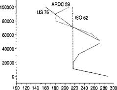
Much effort has been invested exploring the atmosphere. In 1955, President Eisenhower proclaimed the International Geophysical Year, which focused on up­per atmospheric research with sounding rockets. Many measurements were taken and distilled into so-called standard atmospheres. The 1959 ARDC (Air Research Development Command)2 atmosphere was used exclusively for many years until it was supplemented by the U. S. Standard Atmosphere in 1976.3

For simulations that do not require high fidelity, or are limited to the lower regions of the atmosphere, simple functions are used. For the three-DoF simula­tions of this chapter and the five-DoF simulations of Chapter 5, we use the 1962 International Standard Atmosphere or ISO 2533, summarized here.

Troposphere (altitude H < 11 km):

Temperature (°K) T = 288.15 – 0.0065Я

Подпись: Pressure (Pa) p = 101325Subsystem Models5.2559

where H is in meters.

Tropopause-stratosphere (altitude 11km < H < 80 km):

Temperature (°K) T = 216
Pressure (Pa) p = 22630е^0 000157б9(я_11000)

where H is in meters.

Endo-atmosphere (altitude 0 km < H < 80 km):

, p

Density (kg/nr) p = — Kl

Sonic speed (m/s) a — *JyRT

Dynamic pressure:

Mach number:

m=v-

a

Temperature and pressure are the primary variables, approximated by functions, whereas density is derived from the perfect gas law (R gas constant) and sonic speed from the adiabatic flow formula (y = 1.4 ratio of specific heat for air).

The three atmospheres are almost indistinguishable in the troposphere. Only in the stratosphere do we see differences in temperature (see Fig. 8.2), whereas density and pressure are already so low that any distinction is washed out. The ARDC atmosphere is used in space ascent and hypersonic vehicle simulations that require high fidelity, e. g., the CADAC GHAME6 six-DoF model. The U. S. 76 atmosphere is recommended for in-atmosphere and stratosphere simulations that do not exceed 86 km altitude. You find it implemented in the CADAC FALCON6 simulation.

Standard atmospheres are useful for comparative trajectory studies, but, of course, no airplane ever encounters it. There is so much seasonal and diurnal variability that any exhaustive analysis should include an atmospheric sensitiv­ity study. You can consult the literature, like the Handbook of Geophysics,4 and

Altitude

meter

Subsystem Models

Temperature °K

Fig. 8.2 Comparison of standard atmospheres.

find the so-called hot and cold atmospheres at various latitudes—the CADAC weather deck allows you to enter them in tabular form. Or, because the U. S. 76 atmosphere is normalized to standard sea-level conditions, you simply change the sea-level values for temperature, pressure, and density and build your own generic variations.

Polar Equations

The derivation of the polar equations is more complicated. We have to transfer the rotational derivative of Newton’s equation first to the Earth frame and then to the reference frame associated with the geographic velocity. Only then have we created the intuitive format we desire.

The point of departure is again Eq. (8.1). First, we deal with Newton’s acceler­ation afs = DlvlB and transform the rotational derivative to the frame E:

DrvB = DEvB + Г2 EIvIB

Then we substitute Eq. (8.3) into both terms on the right-hand side:

DlvlB = Dev f + DE(nElsBi) + SlEIvEB + nEInEIsBi (8.8)

Apply the chain rule, realizing that Earth’s angular velocity is constant

DE(nEIsBi) = DEnE, sB, + nEIDEsB, = nE, DESBi

and expand the term further by the vector triangle sBi = Sbe + s ei, making use of the facts that Sei = 0 and that the geographic velocity is defined by v § = DesBe’-

Ue, Desbi = nEr(DEsBE + DesEi) = nElDEsBE = nElvE

Substituting into Eq. (8.8) and collecting terms yields

D’v’B = Deveb + mEIvEB + nEInEIsBi

Now we introduce the velocity frame V, which is defined by its three base vectors V], V2, V3.The direction of the geographic velocity vector vf defines Vi, while v 2 is normal to it and horizontal and V3 completes the triad. Transforming the rotational derivative DEvB to the V frame yields the final form of the inertial acceleration:

D’vB = Dvv I + + inEIvEB + nEInEIsBi

We are ready now to replace the rotational derivative in Newton’s law and thus obtain the translational equation of motion

DvvEB+nVEvE = -fap+g – mEIvE – nEInEIsBI (8.9)

m

It contains the famous Coriolis 2EIeivb and centrifugal EIeiEIeiSbi accelerations, which we encountered already in Sec. 5.3.1. Another integration yields the position Sbi of the missile c. m. В wrt the center of Earth / (recall that points / and E coincide):

DEsBi = vE (8.10)

These are six coupled differential equations. As intended, the missile’s acceler­ation is referred to the velocity frame. This shift in reference frame introduced the angular velocity u>VE of the velocity frame wrt Earth.

For a nonrotating Earth the equations are uncoupled and reduce to the flat-Earth three-DoF model

Dvveb + Uveve = ±fap+g
DesBe = vf

where Earth’s reference point E can be any fixed point on Earth.

Equations (8.9) and (8.10) are valid in any coordinate system. We pick the flight – path coordinates for ease of expressing the geographic velocity vector simply as

[^|]V = [V 0 0]; V = |vf I

However, Earth’s angular velocity and the vehicle’s position are best expressed in Earth coordinates and the gravity vector in geographic coordinates:

Подпись: d VB df+ [QVE]V[VEB]V = -[fa, p]V + [T]VG[gf

L J m

– 2[T]VE[£lEI]E[T]ve[veb]V – [Г]У£[^£/]£[^£/]£[^/]£ (8.11)

Подпись: d sBi d t = [t]VE[vEB}V (8.12)

Some of these terms have simple components:

Подпись: 'du|" df = [V 0 0], [g]G = [0 Ogravdswl)], [o)£/]£ = [0 0 coEI]

The transformation matrices that need to be programmed are [ T VG from Eq. (3.25) and [T]VE = [T]VG[T]GE with [T]GE from Eqs. (3.13).

Polar Equations

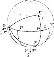
The angular velocity u>VE of the velocity wrt the Earth frame needs special attention. We derive its component form [ooVE~v from Fig. 8.1. It consists of the

vector addition of the angular rates x and у times their respective unit vectors Xj and v2:

VF. , .

<*> = Х*з + yv2

Coordinated

[wVE]v = Х[Т]УХШХ + ylv2Ґ

and expressed in component form

cos у

0

—sin у ~

‘O’

"O’

■ – x sin у –

0

1

0

0

+ Y

1

Y

.sin у

0

cos y_

l

0

xcosy.

The left side of Eq. (8.11) becomes then

rdu^l

V

‘v

Г 0

—X cos Y

Y I

[VI

UVB

+ [ nVEf[vEB)V =

0

+

X cos у

0

X sin у

0

L at J

0

L – Y

-X sin у

0 J

LoJ

V

X V cos у

-Vy

with the three state variables: speed V, heading rate x, and flight-path rate y.

The flat-Earth implementation again is easier to program because the last two terms of Eq. (8.11) vanish and the local-level axes ]L replace the geographic and Earth coordinates

Подпись:-[fa, P]V +lT]VL[g]L (8.13)

г

L

= mVL[vEBY (8.14)

Comparison of Eq. (8.11) with Eq. (8.4) clearly shows the greater complexity of the polar formulation. However, the three state variables V, x, and у are easier to visualize than the inertial velocity components [Ug]7. Under the flat-Earth assump­tion, both the polar equations (8.13) and (8.14) and the Cartesian equations (8.6) and (8.7) are programmed with the same ease. Equation (8.13) actually has the advantage that the angles for the TM 1T]VL are computed directly.

You may have been deafened by my silence over the right-hand side of Newton’s law. The impressed forces consist of surface forces (aerodynamic and propulsive) and volume forces (gravity). Dividing the surface forces by the vehicle’s mass generates what is called the specific force, but actually it is an acceleration. Ac­celerometers of INS measure this specific force. They cannot sense the gravita­tional volume force. In the following sections I delve deeper into the modeling of aerodynamic propulsive and gravitational forces.

Cartesian Equations

We begin with Newton’s second law, as expressed by Eq. (5.9), and expand the right-hand side to include the aerodynamic and propulsive forces fap and the weight mg:

mD‘vlB = fap + mg (8.1)

On the left side is the rotational derivative relative to the inertial frame /, operating on the velocity vB of vehicle c. m В wrt the inertial frame. This inertial velocity [vBV, expressed in inertial coordinates, is suitable as state variable, but not for formulating the aerodynamic forces. It is the movement of the vehicle relative to the atmosphere that determines the air loads. Because the atmosphere is attached to the Earth (no wind assumption), the aerodynamics depends on the geographic velocity vf of the vehicle wrt Earth E. The relationship between inertial and geographic velocities will be derived first.

The position of the inertial reference frame 1 is oriented in the solar ecliptic, and one of its points I is collocated with the center of the Earth. The Earth frame E, fixed with the geoid, rotates with the angular velocity шЕІ. By definition, the inertial velocity is v B = DlsBi, where sbi is the location of the vehicle’s c. m. wrt point I. To introduce the geographic velocity, we change the reference frame to E:

D! sB[ = DesBi + EIeiSbi (8-2)

first right-hand term

De$bi = De$be + DeSei = De$be = vf

where DesEi is zero because sei is constant in the Earth frame. Substituting into Eq. (8.2), we obtain the relationship between the inertial and geographic velocities:

vb ~ vb + ПЕ! вв1 (8.3)

The difference between the absolute values is approximately 465 m/s at the equator.

Now we are prepared to coordinate Eq. (8.1) for computer programming. The aerodynamic and propulsive forces are expressed in flight-path coordinates ]v, whereas the gravitational acceleration is given in geographic axes ]G. Because the state variables are to be calculated in inertial coordinates, we introduce the transformation matrices [T]GV and T’G and write the component form

Подпись: d tПодпись: m= [T f[T }VG[fa, p]v + m[gf) (8.4)

These are the first three differential equations to be solved for the inertial velocity components Wgl1. The second set consists of the inertial position coordinates

Подпись: d.S/j/ df = K]’ (8.5)

Don’t forget the initial conditions. You need to specify the velocity and position vectors at launch.

Two transformation matrices must be programmed. The geographic wrt the inertial coordinates TM is composed of the TMs [T]G1 = [T аЕ[Тш, provided by Eqs. (3.13) and (3.12), respectively, whereas [T]VG is given by Eq. (3.25).

For aircraft and tactical missiles you can simplify your simulation by substituting Earth as inertial frame. In Eqs. (8.4) and (8.5) you replace frame / and point I by frame E and point E. The distinction between inertial and geographic velocity disappears and the geographic coordinate system is replaced by the local-level system L:

Cartesian Equations= [T)VL[fa, P]v + m[g]L (8.6)

Подпись: d SBE d t = [vEBf (8.7)

Only one TM [T]VL is required and is given by Eq. (3.29). These equations of motion are quite useful for simple near-Earth trajectory work.

The Cartesian formulation is the easiest to implement among the three options. It only suffers from a lack of intuitiveness. Who can compose the inertial velocity [Ug]7 and position [лщ К components into a mental picture? Because of this defi­ciency, the polar equations are sometimes preferred. They formulate the equations of motion in terms of the geographic velocity v f, which is much easier to visualize.

Equations of Motion

Before Newton’s law can be applied, the choice of the inertial frame must be made. In Chapter 5 we discussed the options and Chapter 3 defined the frames. Most Earth-bound simulations use the J2000 inertial frame (see Sec. 3.1.2.2) or sometimes the Earth itself for vehicles that hug the ground. We shall focus on the J2000 frame to support the equations of motion for rockets and hypersonic vehicles. En passant, I will point out the simplifications that lead to the formulation over a flat Earth.

The derivation of the Cartesian approach is straightforward. The inertial position and velocity coordinates are directly integrated, and the forces, given in flight-path coordinates, are transformed to inertial coordinates.

The polar approach is used to track the effects of the Coriolis and centrifugal accelerations. Newton’s law is transferred to the rotating Earth frame and expressed in flight-path coordinates. No transformation is necessary for the forces.

Three-Degrees-of-Freedom Simulation

What a journey it has been so far! Provided you have not skipped the first seven chapters, you have reached Part 2 with a tool chest full of gadgets that aspire to be used for challenging simulation tasks. You are trained in coordinate systems, translational and rotational kinematics, and are able to apply Newton’s and Euler’s laws to the dynamics of aerospace vehicles.

If you skimmed over the first part, because of your maturity in such matters, you are also welcome to join us. Make sure, however, that you understand my notation and the invariant formulation of dynamic equations. Then it should be easy for you to follow us. To make the following three chapters self-contained, I will derive the equations of motion from first principles.

Let us ease into the world of simulation with simple three-DoF, point-mass models. They are suitable for trajectory studies of rockets, missiles, and aircraft. All you need is an understanding of Newton’s second law and basic aerodynamic and propulsion data. In no time will you be productive, churning out time histories of key flight parameters. The more sophisticated five – and six-DoF simulations are left for the following chapters.

In preliminary design, vehicle characteristics are often sketchy and aerodynam­ics and propulsion data only known approximately. There may be just enough infor­mation to build simple three-DoF simulations. Fortunately, the trajectory of the c. m. of the vehicle is of greater interest than its attitude motions. Therefore, these three – DoF simulations are very useful for initial performance estimates and trade studies.

Newton’s second law governs the three translational degrees of freedom of three-DoF simulations. Aerodynamic, propulsive, and gravitational forces must be known. In contrast to six-DoF simulations, Euler’s law is not used, and body rates and attitudes are not calculated. Therefore, there is no requirement for aerodynamic and propulsive moments.

In deriving the equations of motion, three different perspectives can be taken according to the state variables selected for integration. Vinh1 takes the direct approach and derives the equations for the following state variables: geographic speed, flight-path angle, heading angle, radial distance, and longitude and latitude. The isolation of the state variables on the left side of the differential equations requires complicated manipulations that are not documented in his book. (Vinh’s equations are implemented by the TEST case, supplied with CADAC-Studio.)

The second method, the so-called Cartesian approach, formulates the equations in Cartesian coordinates. The state variables are the vehicle’s inertial velocity and position components [ujj]7 and [лй/]’, expressed in inertial coordinates.

The third method takes the perspective of the missile’s velocity vector wrt Earth [и|]’/ in velocity coordinates. Its polar components |uf |, /, у are the velocity state variables and the position states, expressed in Earth coordinates. We

refer to it as the polar approach.

The derivations of the Cartesian and polar equations of motion will be pro­vided first as invariant tensor forms and then expressed as matrices for program­ming. Before you can code up the simulation, you need to have some elementary understanding of the atmosphere, gravitational acceleration, aerodynamics, and propulsion. To help you take the first step, I include two example simulations of a three-stage rocket and a hypersonic vehicle. The complete code is provided on the CADAC CD as ROCKET3 and GHAME3.

Roll/yaw inertial coupling

Finally, we use the third of the attitude equations, Eq. (7.85),

qrp(I – h) , N

r =————————–

h h

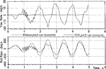
and study the inertial coupling of roll rate p into yaw rate r in the presence of a sustained pitch maneuver qr. A new reference trajectory is needed. With a pitch control of 1 deg, we generate a planar trajectory whose pitch rate qr peaks at — 150 deg/s and its angle of attack a at —30 deg. Now we excite the roll channel with a sinusoidal roll control input of 0.1-deg amplitude and 1-s period. The coupling of roll via pitch into yaw is shown in Fig. 7.8. In the presence of pitch – rate transients, the yaw rate is oscillatory with the period of the roll perturbations and peaks at 15 deg/s. If the pitch control is zeroed, the missile flies ballistic, and the coupling of roll into yaw disappears.

In summary, the perturbation equations of missiles during unsteady flight were derived from the general six-DoF equations of motion, and the aerodynamic forces and moments expanded in the Taylor series up to second-order terms. With these equations we interpreted the results of a six-DoF air-to-air missile simulation.

The aerodynamically induced rolling moment couples into the pitch channel during a yaw maneuver. The yaw channel is excited by rolling motions in the presence of a pitch maneuver. All three attitude channels are mutually linked by aerodynamic and inertial coupling.

These perturbation equations give insight into the dynamics of agile missiles. They shed light on the stability characteristic and should guide the control engineer in suppressing unwanted coupling effects.

Roll/yaw inertial coupling

Fig. 7.8 Yaw-rate response caused by roll oscillations in the presence and absence of reference pitch rate.

With these rather sophisticated dynamic escapades, I conclude Part 1. I hope you enjoyed the ride and did not fall asleep earlier from sheer exhaustion. We solved simple geometrical problems, wrestled with the kinematics of translation and rotation, and derived the equations of motion thanks to Newton and Euler. We followed our motto “from tensor modeling to matrix coding” faithfully and saw no reason to deviate from the hypothesis that all dynamic problems can be formulated by points and frames. If you solved the majority of the problems at the end of each chapter, you should have reached the pinnacle of dynamic bliss.

Now has come the time to put all theoretical knowledge to practical use. As the structure follows the blueprint, so do simulations proceed from modeling. In Part 2 you will be challenged to put your new-found skills to work and develop three-, five-, and six-DoF simulations.

References

‘Etkin, B., Dynamics of Atmospheric Flight, Wiley, New York, 1972.

2Hopkin, H. R., “A Scheme of Notation and Nomenclature for Aircraft Dynamics and Associated Aerodynamics,” Royal Aircraft Establishment, TR66200, Famborough, U. K., June 1966.

3Noll, W., “On the Continuity of the Solid and Fluid States,” Journal of Rational Mechan­ical Analysis, Vol. 4, No. 1, 1955, p. 17.

4Maple, C. G., and Synge, J. L., “Aerodynamic Symmetry of Projectiles,” Quarterly of Applied Mathematics,” Vol. 6, Jan. 1949, pp. 315-366.

5Zipfel, P. H., “Aerodynamic Symmetry of Aircraft and Guided Missiles,” Journal of Aircraft, Vol. 13, No. 7, 1976, pp. 470-475.

6Pamadi, B. N., Performance, Stability, Dynamics, and Control of Airplanes, AIAA Ed­ucation Series, AIAA, Reston, VA, 1998, Chap. 4.

Problems

7.1 Yaw stability equations. To support the design of a simple yaw damper for an aircraft, you are requested to derive the state equations of yaw rate r and sideslip angle /6. Start with the linear perturbation equations (7.55) and (7.56) and use linear aerodynamic derivatives. The desired form is

LN? I

r

Г LNsrl

Г0

A

+

YSr

V.

. V.

Sr

Roll/yaw inertial coupling

State clearly the assumptions that lead to this formulation.

7.2 Fill in the details. Apply your tensor manipulative skills and fill in the intermediate steps between Eqs. (7.16) and (7.17).

7.3 Missile linear perturbation equations over the flat Earth. Start with Eqs. (7.55) and (7.56) and derive the full linear dynamic equations of a missile with tetragonal symmetry. Which equations are coupled? Can you group them into two uncoupled sets? Compare your equations with the stability equations for aircraft in Pamadi’s book.6

7.4 Aircraft pitching moment derivatives. Expand the M derivative of an aircraft up to second order.

7.5 Six-DoF aerodynamic model. You are asked to develop the aerodynamic model for a six-DoF aircraft simulation. Mach number and angle of attack vary extensively so that you are directed to build your aerodynamic coefficients as ta­bles in M and a. The other variables fi, a, fi, p, q, r and the controls 8a, Se, 8r experience only small excursions and are therefore to be modeled by linear deriva­tives. The aircraft reference area is S, its mean chord c, its span b, and its speed V. Write down the aerodynamic force and moments in terms of the nondimensional stability and control derivatives.

7.6 Effect of Centrifugal Term. The state space formulation, Eq. (7.68), of rate and acceleration dynamics is very useful for controller design. We obtained this simple form by neglecting gravitational and centrifugal terms. Now, you are to derive the terms that we neglected, because of disregard of the centrifugal effect. Conduct the derivation that leads to Eq. (7.68), starting with Eq. (7.55) but without neglecting the centrifugal term. Compare the two formulations and discuss the effect of the centrifugal term on rate and acceleration dynamics.

Aerodynamically induced rolling moment

7.5.2.3 The open-loop hor­izontal turn of Fig. 7.4 will serve as a test case. It is generated by 10-deg yaw control and is typical of a 50-g (peak) intercept trajectory.

First, we study the aerodynamic rolling moment and its effects on the roll ex­cursions of the missile. Then we trace the inertial coupling of roll into the pitch channel, and finally create a hypothetical case without the induced rolling moment to highlight the lack of transient dynamics.

The rolling-moment equation is the first of the attitude equations, Eq. (7.85):

1 1

p = —L = —(Lpp + LSp8p + Lwvwv Л—— )

11 1]

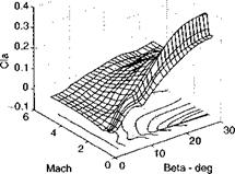
with the key nonlinear derivative Lwv coupling vertical and lateral perturbations into the roll channel. The nondimensional equivalent of this derivative is Q0<l. For our prototype missile the Qo derivative is plotted against fi for various Mach numbers in Fig. 7.5. As fi increases, so does the roll coupling, particularly in the transonic regime.

Aerodynamically induced rolling moment

Fig. 7.5 Cia derivative vs /3 and Mach.

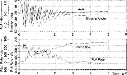
For the test trajectory of Fig. 7.4, the incidence angles and pitch and roll rates are plotted in Fig. 7.6. The severe lateral turn is executed with sideslip angle f5 as high as —40 deg. In the presence of even small a, a large roll rate builds up, leveling out at —600 deg/s.

Inertial coupling enters through the second of the attitude equations, Eq. (7.85):

. rrp(I2 – h) , M —h~+h

The sustained yaw rate rr of the lateral turn multiplies with the roll-rate perturba­tions p and generates pitch-rate perturbations q that grow to 250 deg/s.

Figure 7.6 traces both the aerodynamic and inertial coupling from the roll to the pitch channel. As a hypothetical exercise, we can ask the question, what happens

Aerodynamically induced rolling moment

Fig. 7.6 Induced aerodynamic roll-rate coupling into pitch channel.

Подпись:Подпись:Подпись:Подпись:Подпись:

Aerodynamically induced rolling moment

CCo

.c

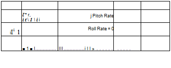
if the aerodynamic rolling moment is absent? I deleted the roll coupling terms in the simulation, repeated the test case, and plotted the result in Fig. 7.7.

Without the induced rolling moment the roll rate is zero, and the pitch rate reflects only the small angle-of-attack transients without any inertial cross coupling.

Aerodynamic cross coupling

Just as for aircraft, it is difficult to model the aerodynamic forces of missiles in a form that can be analyzed and eval­uated quantitatively. Because the functional form is not known, the aerodynamic functions are expanded in a Taylor series in terms of the state variables relative to a reference flight. To capture the rolling and other cross-coupling effects, we have to include at least second-order derivatives.

Let us go back to Sec. 7.3.1 to sort out the existence of the derivatives. The tetragonal symmetry of our missile implies that certain derivatives are vanishing. The expansion of the aerodynamic force and moment perturbations Y, Z, L, M, N is carried out up to second order. Those that survive the symmetry test are listed in Table 7.3. The derivatives in the x direction are disregarded because we maintain the Mach-number dependency in tabular form.

The second column of Table 7.3 displays all of the familiar linear derivatives, whereas the remaining columns show the second-order derivatives. Notice that all of the second-order derivatives of the yaw and pitch channels are dependent either on roll rate p or roll control deflection Sp. The rolling moment itself is a function of incidence angles (represented by v and w), yaw, pitch rate (r, q) coupling, and the effects of yaw, pitch control (Sr, Sq).

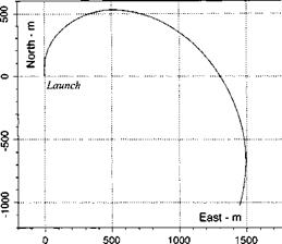
As a practical example, consider an air-to-air missile, executing a lateral ma­neuver toward an intercept (see Fig. 7.4). To generate the lateral acceleration, the airframe develops v or, equivalently, sideslip angle. Although the missile does not roll to execute the maneuver, the roll channel will be excited by the aerodynamic coupling, assuming the vertical channel is also active. There will be vertical chan­nel transients because w or, equivalently, angle of attack is necessary to maintain altitude. Once the roll DoF is stirred, it couples back into the longitudinal and lateral channels.

In the example all of the first – and second-order derivatives play a part, with the control effectiveness derivatives excited by the control fin deflections. It is easy to

Aerodynamic cross coupling

Fig. 7.4 50-g lateral maneuver.

cogitate about these yaw/pitch/roll cross-coupling effect, but the difficult part is to flesh out the skeleton of Table 7.3 with numerical values. Particularly challenging are wind-tunnel tests that measure unsteady derivatives associated with the body rates p, q,r and the incidence rates ii, w.

For our limited discussion we focus on the important Lwv derivative that causes roll torques in the presence of angle of attack and sideslip angle. Once the roll rate is stirred, we investigate the inertial coupling into the yaw channel in the presence of pitch rate.

To test the coupling effects, I use the CADAC SRAAM6 simulation, a generic air-to-air missile. I keep its rather complex aerodynamic model and the propulsion subroutine, but bypass the guidance and control loops completely. Fortunately, the missile airframe is aerodynamically stable—though somewhat oscillatory—thus enabling open-loop computer runs.

Perturbation Equations of Agile Missile

Agile missiles execute severe maneuvers for target intercepts. Seldom do they experience steady flight conditions. To study their flight dynamics, the perturbation equations of unsteady flight are derived, and the aerodynamic forces and moments expanded into derivatives. The second-order derivatives disclose the strong cou­pling between the yaw, pitch, and roll channels.

A six-DoF air-to-air missile simulation, stripped of the flight control system, is used to investigate the aerodynamic and inertial couplings. We will see that the aerodynamically induced rolling moment couples into the pitch channel during a yaw maneuver, and the yaw channel is excited by rolling motions in the presence of a pitch maneuver.

7.5.2.1 Equations Of motion. Of particular interest is the intercept trajec­tory of a short-range air-to-air missile. Its speed is constantly changing during thrusting, and it is turning in response to maneuvering targets. This reference tra­jectory is characterized by the linear velocity components ur, vr. wr and angular velocity components pr, qr. rr in body coordinates. The perturbation variables consist of the linear velocities u, v. w and angular velocities p, q,r.

We start with the general perturbation equations of unsteady flight, derived earlier as Eqs. (7.38) and (7.39) and repeated here for convenience. The first equation governs the translational and the second the rotational perturbations:

Подпись: dev^ d t Bp

+ m[Q. MBr[sv, BBp + m[sQBI]BP[vIBr]Br

= [efoBp + ШВр + ([T]BpBr – [E])[T]Br! lfgrY


d є со1 dt


KT"


Perturbation Equations of Agile Missile

[єта]Вр + [єт,]Вр

These are two sets of first-order differential equations, each having three state variables: u, v, w modeling the translational and p, q,r the rotational degrees of freedom. The body rates p, q,r couple into the translational equation by the term т[є£2ВІ]Вр[vBr]Br of the attitude equation, and the aerodynamic forces and moments impart additional cross coupling.

Unsteady reference flights are characterized by curved trajectories, i. e., their ref­erence angular velocity [шВг,]Вг is nonzero. Three terms of the perturbation equa­tions contain unsteady terms. The translational equation is affected by m[Q. Br’Br єу’вBr, a centrifugal force, and the attitude equations by the two terms

We are surprised by the roll rate p appearing in four equations. It couples through wr and ry into the translational equations and through r, and q, into the attitude equations.

It is a well-known phenomenon in missile dynamics that once the missile begins to roll, the yawing and pitching channels are adversely affected. Yet, what causes the missile to roll? We have to look for aerodynamic phenomena that induce a rolling moment on the missile.

Table 7.3

First – and second-order derivatives

Linear

Roll-rate

Roll-control

Component

derivatives

coupling

coupling

Y

Yv, Yr,

YltlSp > Yfj;,5p,

Yv, YSr

Yqp, YSqp

ZqSp, Y$q$p

Z

zw, zq,

7 7

e-‘vp> e-‘vpi

Zv$p, Zy§p,

Zyp, Z&q

Zrp, Zsrp

Zrsp, Z&r8p

M

, Mq,

MVp, Мур,

MpSp,

Mw,

Mrp, M§rp

MrSp, MsrSp

N

Nv, Nr,

Nwp, Ny, p,

^wbpi ^wSp і

Ny, NSr

Nqp, N$qp

Nq$p, Ngq$p

Linear

Incidence

Rate

Control

Component

derivatives

coupling

coupling

coupling

L

Lp, L&p

Luiv, L-wvi

^-‘vqy f-‘yq, h, wr,

Lv&qi Ly&q, Lr$q,

Lp, Lsp

Lli)V > LWv

Lwr? Lrq

LwSri L’wSrf Lq&r» ^bqbr