Category Modeling and Simulation of Aerospace Vehicle Dynamics

Hardware-in-the-Loop Facility

Replacing the pilot with hardware turns the flight simulator into a HIL simula­tion. Of course, I am oversimplifying, but the major difference is the absence of the human touch. Otherwise, both run at real time, consist of a mix of software and hardware, and are expensive to operate.

Autonomous systems, like missiles and spacecraft, operate without a human in the loop and are therefore prime candidates for HIL simulations. The control and guidance loops can be closed electronically, and any of the costly visual and vestibular stimuli are superfluous. So, what is a HIL? A HIL simulation is the dynamic representation of a vehicle in real time with subsystems modeled by a combination of hardware and software.

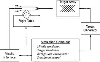
The main elements are shown in Fig. 11.13. The heart is the computer. Here reside the equations of motion and all of those features that must be mathematically

Hardware-in-the-Loop Facility

Fig. 11.13 Elements of an HIL simulation.

modeled, like aerodynamics, propulsion, atmosphere, and gravity. The computer tracks the missile and target geometry and controls the event sequence. The missile attitude angles are sent to the flight table to simulate the attitude dynamics, and, through the missile interface, position and velocity are provided to the missile processor. To close the guidance loop, the missile seeker, whether IR or RF, receives the target signature from the target array, which is driven by the target generator.

There are many variations of this basic theme, contingent on the type of vehicle, availability of hardware, and purpose of investigation. The missile in Fig. 11.13 could be replaced by a cruise missile, an unmanned air-vehicle, or the kinetic kill vehicle of a ballistic missile. Depending on the development phase, we may see breadboard, brassboard, or flight-ready hardware in the HIL facility. Key hardware systems are INS, flight controller, actuator, and seeker.

HIL simulations can be used throughout the development cycle of a flight vehi­cle: from testing of early prototypes to system integration and acceptance testing of flight-ready hardware. Scrutinizing the interfaces between devices from various vendors can prevent much embarrassment during flight testing. (I will never forget the loss of a test vehicle over the Gulf of Mexico because of reversed polarity.)

Not all components of a HIL simulation have to be located at the same facility. For instance, if a missile is to be tested with the armament panel of an aircraft, it is impractical to park the aircraft inside the HIL facility. Instead, the aircraft is linked over fiber optic cable with the wiring harness of the missile.

The degree of distribution can be further expanded. The U. S. Army keeps tank battalions at several locations throughout the world. Each battalion uses tank sim­ulators for training. To practice tactics without burning up fuel, several trainers are linked together to form what is called a distributed interactive simulation (DIS). Sometimes several battalions are netted together for a global training exercise. Sending time-position data over disparate telecommunication nets require tight control of the message traffic. The communication protocol that accomplishes this feat carries also the name DIS. Recently, the U. S. Department of Defense substituted DIS by HLA, a higher-order language protocol.

After this brief excursion to distributed simulations, let us discuss the require­ments of an HIL facility. The system requirements are determined by the system to be tested. The apparatus should allow the system to be tested to its limits. There­fore, the bandwidth of the flight table should exceed the rigid-body frequency of the vehicle, the target model should expose the seeker to all possible frequencies with realistic noise sources and countermeasures, and the actuator should be loaded by the correct hinge moments.

Mathematical models are used for nonhardware subsystems or to back up hard­ware. You should by now have a good idea what they contain. Make sure to balance the model fidelity evenly across the HIL. Any or all of the components can be modeled in code. Sometimes the HIL simulation of a new vehicle can start as an all-digital simulation. As the development program progresses, hardware is substituted, as it becomes available. The computer language today is most likely C or C++, but you may have to work with legacy code in Pascal or FORTRAN or even the simulation language ACSL. Above all, it is important to establish and maintain good configuration control.

The credibility of your study depends on the extent of the verification, valida­tion, and accreditation process preceding it. First, verify that the hardware and software performs as specified, then validate your closed-loop simulation against benchmarks and test cases from other sources. Finally, call the user to accredit your simulation by giving their stamp of approval.

The mature HIL simulation is not static. It needs maintenance and must be upgraded. The hardware needs probably more maintenance than the software, but even software in today’s volatile upgrade-driven market must be kept up to date. And who can claim a bug-free simulation? As errors are discovered, they must be eradicated and the corrective action documented. Establish a budget for maintenance and realize that upgrades are a way of life.

Real-time conversion

Converting the batch simulations of the design phase to real-time code is often a disjointed process. Frequently, the MIL simulator has its own tightly integrated missile fly-out model. In some instances the same aerodynamic and autopilot subroutines are engaged in driving the aircraft and the missile, albeit with different data sets. The batch simulation is broken up and distributed over the subroutines of the combat simulator. You can imagine how difficult it is to validate the converted missile simulation. Many test cases have to be run in both environments, analyzed for inconsistencies and adjusted—only to have to execute the test cases again for revalidation.

Integrating the missile simulation as a complete entity streamlines the process, but sacrifices efficiency. CADAC provides a converter program that takes the batch simulation, strips it of unnecessary code, and translates it into a package that can be “dropped” into the MIL simulation. All missile subroutines remain intact, and only the interface variables have to be adjusted. Although this approach requires more code, execution speed remains essentially the same—a small price to pay considering the abundance of memory in modern computers. The rewards lie in the much simplified validation phase and the assurance that the missile model in the MIL simulator reflects accurately its performance.

Real-time conversion

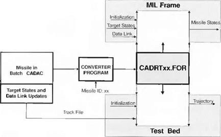
Fig. 11.11 CADAC converter program.

The conversion takes place in several steps and applies equally to five – and six- DoF simulations. After having validated the missile simulation in the batch mode, the programmer runs a test case and records the input to the missile, e. g., target states, on a track file. Then the converter program translates the batch code into a subroutine package, which is validated in the test bed, driven by the track file. Now the code is ready for integration into the MIL frame simulator.

The schematic of Fig. 11.11 depicts this procedure. The missile identification code IDxx, inserted during conversion, attaches itself to every subroutine and labeled common statement. Thus, every missile package becomes unique, and different types of missiles can be flown in the MIL simulator simultaneously.

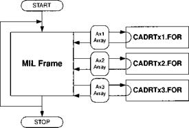
The communication between the MIL frame and the missile simulation oc­curs over a common A array. It is the exclusive conduit for missile initialization, target state tracking, and data link transmission, as well as the missile state feed­back. Figure 11.12 shows the interface with three missile models, named xl, x2, and x3.

In summary, we reviewed air combat maneuvers and focused on the CIC en­gagement, stylized by the LAR-3 launch acceptable region, as the most demanding situation. Employing the five – and six-DoF simulations of a generic SRAAM, we assessed the effect of simulation fidelity on the pilot’s situation awareness. We concluded that five-DoF models, adjusted for six-DoF effects, could be used in CIC. They portray sufficiently accurate the time of flight and the firing zones for the pilot’s situation awareness. However, low-speed, close-in, and large off-boresight shots require six-DoF missile models, or, as a minimum, confirmation of such en­gagements by six-DoF batch runs. Integration of new missile concepts into combat simulators is greatly simplified by a conversion process that leaves the missile code intact, instead of overlaying it on the aircraft model.

Real-time conversion

Fig. 11.12 Interfaces between multiple missiles and MIL simulator.

Miss distance comparison

The other important factor for the pilot is the knowledge whether the missile annihilated the target. For our study miss distance serves as criterion, although the damage to a particular aircraft depends also on the missile’s warhead and fuse. We assume, somewhat arbitrarily, that a 6-m miss is the cutoff point for a hit. Any larger value constitutes a miss.

The simplifications of the five-DoF model, affecting miss distance, are in aero­dynamics, autopilot, and, above all, in the seeker implementation. We replaced the detailed seeker code of the six DoF with an ideal seeker not constrained by gimbals and tracker loop. Multiple runs throughout the LAR-3 envelope with the five-DoF simulation lead, as expected, to hits everywhere. However, if we use the detailed six-DoF simulation with noise-corrupted seeker and sensor models, the envelope changes significantly.

To calculate the LAR-3 envelope for missiles with noise, multiple runs are made against every aimpoint. The miss distances are averaged and displayed as repre­sentative terminal miss performance. We use 30 such Monte Carlo runs against each aimpoint, employing the automated SWEEP methodology of CADAC for analysis and plotting.

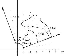
Figure 11.10 displays the results of an engagement at 5000 m altitude with both aircraft executing 7.5-g maneuvers at 0.75 Mach.

Подпись: 500 MODELING AND SIMULATION OF AEROSPACE VEHICLE DYNAMICS

О


Подпись: Seeker Yaw Angle - deg Roll Angle - deg

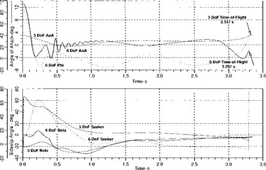
Fig. 11.8 Comparison of six – and five-DoF trajectories. LAR-3: R = 3000 m, A = 45 deg.


Miss distance comparison

Miss distance comparison

Fig. 11.9 LAR-3 time-of-ffight comparison.

Compared to the five-DoF model, which delivers hits everywhere, the envelope is reduced for close-in shots (no hits within 2 km) and at high off-boresight shots beyond 5.5 km. The sweet spot lies at midranges and small look angles. A major reduction in real envelope performance occurs for look angles greater than 70 deg at all launch ranges. It is caused by the seeker gimbal limits. To understand this phenomenon, we need to look at the trajectory more closely.

The maximum look angle of the SRAAM seeker is 90 deg. This allows lock – on before launch throughout the envelope. After launch there is a delay of 0.25 s before guidance is enabled. During this time, the missile tends to align itself with its velocity vector by virtue of its inherent stability. This leads to a horizontal turning away from the target, through an angle perhaps as large as the launch angle of attack and a corresponding increase in seeker pitch-gimbal deflection. Whenever the seeker is locked on before launch at a gimbal angle between 90 and 90-a deg

Miss distance comparison

Fig. 11.10 Six-DoF LAR-3 envelope; 30 Monte Carlo runs against each aimpoint.

(a is the angle of attack of the shooter at missile launch), there is a chance that the weathercock stability of the missile will drive the gimbals to their stops. The reduced off-axis performance is shown in Fig. 11.10. Maximum gimbal deflection is exceeded during the first 0.25 s of flight, and the seeker breaks lock on the target whenever the initial look angle exceeds 72 deg. The kinematic seeker simulation ignores the gimbal stops and provides whatever deflection is required to maintain target tracking.

The situation depicted in Fig. 11.10 signifies the physical limitations whenever launches are made at high angle of attack. Such launches can be common in CIC engagements, but are very rare at longer ranges.

Many CIC engagements, particularly those that feature high angles of attack at launch, are initiated from subsonic conditions. As a result, the low-speed maneu­verability of the missile plays a dominant role in determining whether or not a gimbal limit violation is likely to occur. The characterization of missile airframes intended for a CIC role should, therefore, include accurate subsonic aerodynamics.

In circle fights maximum look angles determine the all-important first launch opportunity of the shooter. If one aircraft is given an 85-deg capability compared to the baseline 70-deg system, its effectiveness is greatly enhanced. For realism, the look angle boundaries must be accurately modeled. Assuming the six-DoF simulation is the truth model, the five degrees of freedom can be brought into agreement by reducing the limiting gimbal deflection input. A maximum pitch gimbal deflection of 70-deg for the five degrees of freedom should lead to an envelope with a maximum look angle very close to that of the six-DoF simulation.

In summary, five-DoF models, adjusted for six-DoF effects, can be used in CIC—and of course in BVR—engagements. They portray sufficiently accurate the time of flight and the in-range/out-of-range envelopes for the pilot’s situation awareness. However, low-speed, close-in, and large off-boresight shots require six-DoF missile models, or, as a minimum, confirmation of such engagements by off-line six-DoF runs.

Fly-out comparison

Any missile model of a combat simulator should reproduce accurately the sequence of events that affect the pilot’s situation awareness. The sequence consists of the missile time of flight, the hit or miss outcome of the firing, and the time required assessing the damage inflicted by hits. This last item is closely related to the missile lethality model. Consideration of lethality however is beyond the scope of this discussion.

The importance of situation awareness cannot be overstated. The purpose for a MIL simulation is to capture the reactions of the pilot and factor them into the assessment of the weapon’s effectiveness. If his perception of the overall combat situation is corrupted by simulation errors, he will react differently, and most ben­efits of a MIL simulation environment will be wasted. This is the principal reason why workstation MIL simulations have only been useful in BVR engagements, but not in CIC battles. The tabletop monitor can provide a good approximation of a radarscope, but cannot reproduce the visual field of view of a human pilot. Therefore, the situation awareness is lost and with it the realistic pilot response, which was the primary goal of the exercise.

Time of flight of the missile and the hit or miss outcome are the foundations of situation awareness. Pilot actions form an unbroken chain of events, based on the pilot’s perception. If the simulation time of flight is in error, say by a half – second, the actions of the pilot during that half-second are ambiguous relative to an actual launch. Initial conditions for any subsequent launch have been changed irreversibly, and system effectiveness may have been reduced to speculation. The same can be said of the hit assessment because the actions of a pilot who perceives a miss will normally be quite different from the one who sees a hit.

The fidelity of the missile model must take into account these requirements. From the standpoint of the simulation facility, the missile code should be as com­pact as possible and executable at the same time step as the aircraft. That is, low-fidelity models would simplify the integration task. However, the simplifi­cations should not jeopardize the pilot’s situation awareness. Because CIC is the most demanding engagement, we look into the adequacy of five-DoF models to represent the missile fly-out in LAR-3-type launch zones.

Time of flight is a critical parameter in determining the adequacy of any missile simulation. A comparison between SRAAM5 and SRAAM6 of a fly-out trajectory in the middle of the envelope is shown in Fig. 11.8.

It is instructive to follow the incidence angles from launch to intercept for the two models. The six-DoF simulation replicates accurately the initial roll angle, imparted to the missile by the shooter aircraft, executing a 7.5-g maneuver at an angle of attack of 13 deg. The missile rolls out to a “hooks-up” attitude and develops sideslip for the lateral intercept. On the other hand, five-DoF simplifications cause the missile to be initialized with a large sideslip angle and small angle of attack because the roll DoF has been suppressed.

This different kinematic behavior is also evident in the yaw seeker gimbal angles. The highly banked missile exhibits very little initial yaw gimbal angle, whereas the simplified five-DoF representation starts out with a correspondingly large value.

Naturally, the pilot is not aware of these missile parameters. He is more interested in the intercept time. The endpoints of Fig. 11.8 show that the missile times of flight of the two versions are very close, within about 1%.

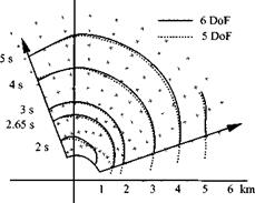
For a broader look a typical LAR-3 (see Fig. 11.6) envelope is displayed in Fig. 11.9. Throughout the envelope the flight times agree well, with the trend that the six DoF exhibits slightly longer times. This tendency is caused by the initial transients, which are more accurately duplicated by the six-DoF simulation. The 2.65-s contour is also included, marking the burn-out of the rocket motor.

Prototype missile

For our performance studies we use the air-to – air missile, introduced as SRAAM5 in Chapter 9 and SRAAM6 in Chapter 10. It is a 6-in. diam/116 in. long, high fineness ratio, body-tail configuration with a 6:1 ogive, blunted for an IR dome with 1.5-in. radius, and forward strakes (see Fig. 11.7). Its forebody includes an imaging IR seeker, electronics, an INS, a cooling bottle, an active optical target detector, and a 20-lb warhead with an electronic safe and arm system.

Подпись: Flight Seeker Control Armament Propulsion Control Diameter 6.0 in Overall length 116 in Tail span 16 in Launch weight 92 kg Burn-out weigth 56 kg Warhead weight 9 kg

The SRAAM is modeled in the CADAC environment. It consists of five – and six-DoF fly-out versions and can be obtained from the CADAC CD. The target is modeled as a point-mass vehicle with its attitude aligned in the load factor plane. The maneuvers are defined before missile launch.

Fig. 11.7 SRAAM.

SRAAM5 represents the so-called pseudo-five-DoF implementations as pre­sented in Sec. 9.3.2. Three translational DoF are modeled by nonlinear differential equations (Newton’s equations) employing tabulated trimmed aerodynamic data. The two attitude degrees of freedom are pitch and yaw (skid-to-turn). They are modeled by linearized differential equations that describe the attitude dynamics of the controlled airframe. In this case Euler’s equations are not modeled.

The SRAAM6 version is a full six-DoF simulation. It solves the three trans­lational DoF with Newton’s equations and the three attitude degrees of freedom with Euler’s equations. All systems of the missile are modeled in detail.

During the missile design phase, C ADAC is executed in the batch mode. Its many postprocessing tools support the performance evaluation of the missile concepts. The same missile simulation can be stripped of all unnecessary subroutines using the converter program CONVRT. EXE, which generates a self-contained subrou­tine suitable for real-time execution. Thus, the tractability of the missile simulation from batch processing to execution in the combat simulator is maintained.

The six-DoF architecture of the batch simulation is shown in Fig. 10.53. Each module represents a major subsystem with its closely controlled interfaces. The calling sequence is important and must be maintained for the simulation. For real­time applications the two modules G1 Target and S2 AI Radar are deleted and are replaced by inputs from the flight simulator.

The five-DoF simulation, presented in Fig. 9.54, was built from the six-DoF simulation by simplifying the aerodynamics and replacing Euler’s equations by the response of the attitude autopilots.

Air combat fundamentals

Air-to-air missile engagements are categorized by launch range. They are beyond visual range (BVR) and within visual range (WVR). Many variables influence the visual detection threshold, from atmospheric conditions to the choice of aircraft color schemes. It is possible for one combatant to be within visual range while his opponent is still hidden, causing BVR and WVR conditions to overlap. CIC encounters are a special subset of WVR engagements.

In CIC engagements the opponents are maneuvering at high load factors almost continuously. These maneuvers cause loss of speed and altitude. Both aircraft descend in spirals, which looks like two dogs chasing each other; therefore, the expression dogfight.

For over 40 years air combat doctrine has called for three types of weapons with overlapping, concentric coverage. Long or medium range air-to-air missiles (MRAAM) are tasked with all BVR engagements. Under BVR conditions the aircraft’s fire control radar detects the target, and the MRAAM guidance is matched by a compatible radar frequency seeker. Large warheads compensated for the inaccuracy of the radar seeker. Thus, MRAAMs tend to be heavy vehicles with sluggish flight characteristics.

Short-range air-to-air missiles (SRAAM) are preferred for the outer portion of the WVR engagements. The typical SRAAM uses an IR seeker, because acquisition ranges are consistent with visual detection. Lighter warheads and motors, made possible by smaller miss distances and fly-out ranges, make the SRAAMs lighter and more agile than MRAAMs.

Finally, the gun is dedicated to CIC conditions. Each fighter pilot tries to shoot at his adversary’s tail. Only recently, are the tactics of the World War II dogfight beginning to change.

With today’s advanced technologies an air-to-air missile can be designed with creditable performance even for CIC conditions. A single missile could be effective over the entire detectable target range, even replacing the gun. In the past, analyses of CIC conditions have generally concentrated on aircraft performance because of the importance of flight quality for effective aerial gunnery. The usual assumption was that the CIC problem had been solved if the shooter could point his aircraft at the target and hold that geometry long enough for his gunfire to take effect.

With the new generations of SRAAMs on the drawing boards, CIC tactics are updated to account for agility and off-axis capability. The missile’s high-g maneuvers require greater fidelity simulations in combat simulators. Because of this new challenge, I will concentrate on the close-in engagements and the issues of missile simulation fidelity.

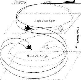
11.1.3.2 Circle fights. In CIC engagements the opponents are maneuvering at high load factors almost continuously. Historically, the most common form has been a hard lateral turn in a steeply banked attitude. Although this maneuver presumes a body-fixed, forward-firing gun, the same tactics has been used in analyses of short-range missile engagements. Viewed from above, the flight paths of the opposing aircraft resemble a series of circles, leading to the terminology of circle fight. Viewed from the side, each successive circle is lower than the previous one, owing to the tendency of aircraft to lose altitude when in a steep bank. Overall, the flight paths of all of the participants in a CIC engagement are descending spirals, as illustrated in Fig. 11.5.

Two stylized types, the single-circle and double-circle fights, are important in CIC analysis. In the single-circle model both opponents hold constant altitude during a circular flight path about a common center of rotation. They could be flying toward each other or chasing each other. In the U. S. the chase version of the single-circle fight is known as a Lufbery circle. The head-on, single-circle fight, however, is considered the more important baseline engagement. In the double­circle fight the opponents fly nonconcentric circular flight paths that are tangent at a single point. Both aircraft turn the same way, either clockwise or counterclockwise.

Before the introduction of air-to-air missiles, these circle fights could easily be assessed. The outcome depended on who could first point the nose of his aircraft at his opponent and keep it pointed there long enough to inflict significant damage with his gun. Aircraft performance and robustness were the deciding factor. These are conflicting design requirements, because an agile aircraft is light, lacking heavy armor and redundant controls. Finding the proper balance shaped the course of fighter development for decades.

Although circle fights were originally used to categorize close-in combat with guns, they have gained new prominence for engagement studies with the new breed

Air combat fundamentals

Fig. 11.5 CIC engagement as a sequence of circle fights.

of agile missiles. The format most often seen in the U. S. is the launch acceptable region (LAR) graphic. There are five distinct LAR graphics; those most relevant to circle fights are given the designations LAR-3, LAR-4, and LAR-5, representing the single, double, and Lufbery circles, respectively. The construction of a LAR graphic can best be described by an example.

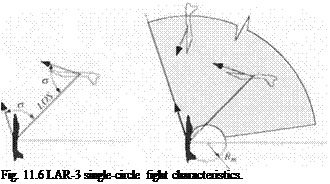
Figure 11.6 illustrates the LAR-3 scenario. The purpose is to simulate a head – on, single-circle fight, at coaltitude and equal speeds. Its prelude begins at great distance, with both aircraft racing straight for each other and trying to fire off their first shot. If both survive the encounter, they merge and begin turning with facing cockpits, setting up the head-on circle.

The geometry of a single-circle fight can be expressed as the relationship be­tween the velocity vectors of the shooter and the target, as shown in the left panel of Fig. 11.6. The slew angle a is the angular displacement of the LOS to the shooter velocity vector at launch. If the target velocity vector makes the same angle to the LOS, the result will describe a single-circle fight.

The LAR-3 envelope follows the format illustrated in the right panel of Fig. 11.6. The shooter aircraft is fixed at the center. The slew angle a is swept incrementally from zero to the largest off-boresight capability of the missile seeker. At each value of (7, the launch range to the target is varied incrementally to identify those initial range conditions that result in hits. The shaded area shown in Fig. 11.6 is the area of successful launch conditions relative to the shooter and is called the launch acceptable region.

Two features of the LAR-3 graphic are noteworthy. First, the full capability of the missile is not normally shown. Because the LAR-3 scenario depicts CIC per­formance, the envelope is truncated at approximately 6 km. The full performance envelope of a missile could extend to greater distances, but is of little interest.

Подпись: Fig. 11.6 LAR-3 single-circle fight characteristics.

A second feature of the LAR-3 graphic is the inner exclusion circle defined by the turning radius of the shooter. Launch ranges within that circle result in a crossover between the flight paths of the shooter and target, and both opponents must turn through at least 180 deg before a true single circle can be established. The situation is physically realistic, but does not fit the “circle choreography” selected for LAR-3.

We will use the LAR-3 engagement to study the fidelity issues associated with CIC. Although there are several other types of engagements—the twin circle fights and the British combat circle diagrams, the LAR-3 is representative of the stressing engagements of typical CIC encounters.

Missile Integration for Combat Simulators

As with all engineering endeavors, air combat simulators are benefiting greatly from increased computer prowess. With the latest Silicon Graphics processors, it has become possible to double the number of aircraft and missiles in simulated combat, while even improving the fidelity of their models.

Air combat simulators are piloted flight simulators that engage multiple air­craft and missiles simultaneously. They support all phases of aircraft and missile development. During the definition of requirements, they are used to establish air­craft maneuverability and missile fly-out performance. In the development phase competing designs are evaluated on simulators. Eventually, the airman is trained on them for combat.

Depending on the implementation, we distinguish between dome, workstation, and virtual helmet simulators. At the current state of the art the dome simulators provide the highest situational awareness, but may be replaced by virtual helmets in the future. A poor-man’s choice is the tabletop workstation.

The software that drives the air combat simulators has a long history of devel­opment. The equations of motion of the vehicles are well understood. However, the fidelity of the models is restricted by the limitations of the computer hardware. Although the aircraft are modeled in six degrees of freedom, the missiles in current simulators are simplified point-mass formulations in three degrees of freedom or pseudo-five degrees of freedom.

With the increased reliance of the developer on prototyping by computer, it has become necessary to improve the fidelity of the missile model. Particularly for close-in combat with its highly dynamic environment, the missile should be modeled with six-DoF fidelity, or at least any simplification should be validated against it. Fortunately, the continued increase in computing power will eventually allow full six-DoF representation of aircraft and missile models in air combat simulators.

To shorten the time of the design and evaluation cycles, the simulation models should be adaptable to both activities: execution in batch mode for design and real-time implementation in simulators. The batch simulation is built first, then converted into a real-time capable subroutine, which is embedded into the air combat simulator.

I will first describe standard air combat maneuvers as they affect modeling choices, discuss the effect of missile model fidelity, and describe a typical con­version process from batch simulation to real-time code. Your knowledge of five – and six-DoF simulations and particularly your familiarity with the SRAAM5 and SRAAM6 models will be an asset.

Motion system

Although, according to physiologists, 70% of flying is accomplished with the eye, the ear plays also a very important role. It relates wind and motor noises to airplane speed and status of the engine. But more important than the eardrum is the inner ear with its vestibular set of sensors.

The vestibular sensors consist of the inner ear canals, which measure angular acceleration, and the inner ear otoliths (little calcium stones), which sense linear acceleration. Isn’t it interesting that an INS senses the same parameters with its gyros and accelerometers? Our brain carries out the integration, although not as accurately as the INS computer. Close your eyes while in the passenger seat of a car. Although you can sense the accelerations, to deduct the velocity or even the traveling distance is a difficult task.

This feature of the human ear is stimulated by the motion platform, which supports the cockpit. It is impossible and unnecessary to duplicate the aircraft’s velocity and position, but the accelerations are important stimuli.

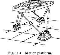
The motion platform is supported at three points by a pair of hydraulic cylinders each (see Fig. 11.4). Cylinders from opposing points are paired and attached on the floor. This arrangement gives the platform three translational and three attitude degrees of freedom, a true six-DoF dynamic structure. Although the platform is restrained, the onset of linear and angular accelerations can realistically be simulated. So-called washout filters quickly fade out the signals to restrict travel.

For midsize simulators the linear travel is typically 3 m and the rotational excur­sions about ±30 deg. Powerful hydraulic lifters support the platform. They deliver

Motion system

a motion bandwidth of 2 Hz, commensurate with the upper limit of typical rigid airframe dynamics.

The linear accelerations of civilian airplanes rarely exceed one g, i. e., one times the Earth’s gravity. However, fighter pilots, practicing dogfights, routinely ex­perience 3-5 g. They wear pressure suits to prevent blood from accumulating excessively in the lower part of the body, causing blackout. They certainly can attest to the seat-of-the-pants (somatosensory) feeling.

Because the motion system cannot simulate sustained g loads, the pressure suit can be enlisted to mimic g effects. Particularly in military simulators with the pilot willing to suit up, the somatosensory feedback is provided by a specially designed pressure suit. It cannot duplicate the spine-jamming agony, but still conveys the sense of sustained maneuvers.

Simulators penetrate ever-deeper flight training. They are cheaper than air time, allow practicing emergency procedures without endangering life, and are essential for single seat aircraft. The U. S. Air Force is so infatuated with simulators that it broke with tradition and bought only single-seat F-22 fighters. All flight training is done on the ground in two facilities.3 The Full Mission Trainer (FMT), set inside a geodesic dome with 360-deg view, is used for flight training and emergency egress procedures. The Weapon Tactics Trainer (WTT) is a workstation simulator with up to 21 stations, manned by blue and red pilots. Here the war fighters can hone their skills in acquiring, tracking, and attacking enemy aircraft. The F-22 pilot training lasts about 104 days, 10 days less than for the F-15, but covering a more complex aircraft. Wouldn’t you want to be part of the action? Well, you can. Go to your software store, buy an F-22 simulator, and then fly away on your home computer!

Cockpit Simulator

The cockpit simulator encompasses all of the elements displayed in Fig. 11.1. The fledgling pilot is subjected to a complete palette of the sensory feedback: visual, vestibular (balance of the inner ear), somatosensory (seat-of-the-pants), and aural (acoustic). If these features are well integrated, the simulator will pass FAA Level D certification, authorizing its use for all flight training without air time. The airlines train their pilots in cockpit simulators, and the military services make use of specialized trainers. For instance, the V-22 Osprey trainer satisfies very demanding requirements and complies with Level D certification.

11.1.2.1 Vision system. Our eyes are a marvelous creation. Collaborating with the brain, they are able to process information unequaled by any computer. Their specification or I should say their physiology reads as follows: field-of-view for stereoscopic vision, horizontal ±70 deg, vertical ±50 deg; eye movement, ± 10 deg at 500 deg/s; head movement, ±100 deg at 10 to 100 deg/s; and resolution in the central region of the retina, 1 arc min (0.3 mrad). These characteristics must be matched by the vision system. It should be stereoscopic, with large field-of-view, high resolution and fast response.

Cockpit Simulator

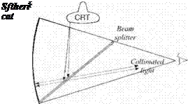
Not all of these requirements can be realized. Fortunately, stereoscopic pictures are not mandatory because the scenes are far removed. However, with close-up CRT screens, the impression of distant scenes must be created by collimating the light that enters the two eyes. Figure 11.2 shows the principle. The beam from the CRT is reflected off the beam splitter, to be returned by the parabolic mirror

Cockpit Simulator

Fig. 11.3 Generation of visual scene.

through the beam splitter into the eye as collimated beams. The eye perceives the scene to be at infinity. A typical value for the horizontal field-of-view is ±48 deg and vertically ±36 deg. The refresh rate should be at least 30 frames per second to be flicker-free.

The scenes themselves derive from video tape or digital imagery. Figure 11.3 depicts the process. The position and attitude of the aircraft and the perspective of the pilot’s eyes are correlated with the three-dimensional visual database. A geometry processor projects the selected portion onto the two-dimensional plane and sends the polygons to the video display.

Many of the scenes are computer generated. However, for best effects, photo­graphic pictures are used. You may even find photographic objects superimposed on a digital terrain database. Scene generation is the most computer-intensive part of a simulator. Its realism is a direct function of the invested computer power.

. Workstation Simulator

Workstation simulators are CRT screen-based, man-in-the-loop simulators with processors of high-end workstations. Several processors, linked by Ethernet pro­tocol, support distributed computing. The aircraft and missiles are executed si­multaneously with their display utilities. Typically, the pilot sits at a two-screen display with throttle, stick, pedals, and keyboard as input devices. The upper screen displays the background scene, superimposing the heads-up display. It also can contain the radar, tactical display, and an attitude indicator. The lower screen is re­served for the remaining aircraft instrumentation—the so-called lookdown display.

The number of piloted stations depends on the objective of the simulation. Flight training requires just one station, whereas air-to-air combat calls for multiple sta­tions, simulating blue and red aircraft. The maximum number is determined by the outlay of the processors. Workstation simulators make it possible to conduct studies with many piloted aircraft without large investments. Military tactics, like engagement maneuvers, choice of weapons, and egress maneuvers, can be devel­oped and practiced. However, their utility for flight training is restricted because of limited situational awareness: the pilot’s view is confined to the flat screen display, and no tactile feedback is provided. In workstation simulators you will find a mixture of models. Highly detailed aircraft dynamics with six-DoF aero­dynamics, multimode flight controls, high-bandwidth actuators, navigation aids, gears, and flaps. The missile trajectories are often modeled as simple three-DoF or pseudo-five-DoF simulations. Rarely will you encounter a full six-DoF missile representation. The reason is simple. The pilot’s attention is focused on the air­craft’s behavior as he delivers and evades missiles. Any obvious discrepancy with his flying experience will distract him from the simulation’s objective. The missile fly-out, on the other hand, is autonomous, and only the flight time and the effect on the target are of interest to the pilot. Therefore, simplified missile simulations are acceptable as long as they have been validated previously by full six-DoF models.

Most of the simulation code is programmed in FORTRAN. A long legacy exists of flight dynamics, autopilot and radar models, adapted to the characteristics of new
systems, as required. The graphics interface is highly dependent on the simulation hardware and has changed drastically over the past decade. Today, C++ is the preferred language to interface the hardware and the displays. Both FORTRAN and C++ interact harmoniously in workstation simulators, although the purists would like to deal only with a single language.

Let us observe the genesis of a project from planning to execution. Assume the objective is to study the effectiveness of a new air-to-air missile in an air combat environment. Well before the pilots arrive, in some instances 12 month in advance, a planning meeting is held with the customer, the aircraft and missile designers, and the simulator personnel. The objectives are defined, the aircraft and missiles identified, and the scenarios discussed. If new flight systems are introduced, the facility programmer is given their code, which he will integrate into the simulation environment. Here, the first problems can arise. The new missile or aircraft must run as subroutines callable from the main program, usually referred as the man – in-the-loop (MIL) frame. The input and output to the subroutines must be well defined, preferably formalized by an interface document.

You will encounter two approaches to the integration. The older technique, the distributed integration, breaks the flight system into its individual components and incorporates only the new subroutines like aerodynamics and flight controls into the MIL frame, while reusing such basic equations as translational and attitude motions. With today’s abundance of computer memory, the newer approach, the compact integration, inserts the complete missile or aircraft into the MIL frame. It has the advantage that the code, after having been thoroughly checked out in a batch environment, is executed in its entirety in the MIL frame, thus eliminating the time-consuming validation phase.

After the MIL frame programmer has updated his simulation environment, the engineering trials are conducted as final system check. An experienced pilot at this point would be helpful in uncovering any flight anomalies. Once checkout is complete and the air combat simulation has been validated, the test-planning meeting is convened, attended by the customer, the designers, the programmers, and the pilots. They establish the scenarios, concur on the parameter space of the design variables, and lay out a detailed run schedule.

Finally, the time has come to call the pilots for the combat trials. During the first week, they are briefed on the mission objectives and the scenarios and given an opportunity to develop their tactics. Sometimes they question the fidelity of the simulator and the “feel” of the aircraft response. If you are the facility programmer, you have the difficult task to convince the pilots of the adequacy of your simulation for the planned trials. Once they understand that the compromises you had to make do not adversely affect their combat skills, you have won them over, and you can start with the actual test.

The conduct of the trials closely follows the established plan. The engagements are flown, the missiles launched, and the intercepts recorded. Then the parameters are changed, and the cycle repeated. All data are recorded for analysis.

During the post-trial analysis, before the measures of effectiveness are evalu­ated some of the stressing engagements must be validated. The recorded data are replayed and scrutinized. Miss distance values, which depend on the fidelity of the missile fly-out simulation, must be verified. The analyst may even have to take recourse to the original six degrees of freedom. He or she drives it with the actual
target motions and duplicates the engagement based on the high-fidelity simula­tion. Eventually, the results will be expressed in blue and red fighter exchange rates and conclusions drawn as to the best aircraft and missile designs.

Workstation simulators are particularly effective training tools for managing the aircraft’s systems. Radio communication, flight planning, and troubleshooting faulty devices are some of the exercises that can be practiced. The U. S. Air Force uses them as weapon tactics trainers, giving the pilot hands-on experience with fire control radars and weapon release switchology without expending missiles. However, to submerge the trainee into the complete flight experience the more elaborate cockpit simulator is essential.