Category Noise Sources in Turbulent Shear Flows

General Solution

For the sake of generality, assume a prescribed source distribution S(y, t’) radiating in a volume of space V (t’) limited by possibly moving surfaces S(t’). The local normal on the surfaces n is pointing outwards the volume. The wave equation for the scalar field variable v to be solved is written as

Подпись: 1 d2v C0 dt'2S.

Подпись: 1 — c2 dt'2
Подпись: S(x - y) S(t - t'),

Is called a Green’s function for this equation and noted G any solution in the case of an impulse point source, according to

General Solution General Solution General Solution

where S is Dirac’s delta function. G depends on four variables and represents the field produced at point x and time t by an elementary source at point y and time t’. If the effect of initial conditions is ignored, which is justified for periodic or stationary random processes, the formal solution for the scalar field follows as (Goldstein (1976))

The Green’s function is not unique as long as no boundary condition is involved in its definition, but its expression must be known in order that explicit solutions are derived. The so-called tailored Green’s function would provide the field produced at point x and time t by an elementary source at point y and time t’ in the presence of the surfaces. If it can be known and introduced in the solution, then the surface integral vanishes. The corre­sponding explicit result generally leads to closed-form solutions. If another Green’s function is used, the result is implicit and the formal solution is an integral equation. The simplest statement is obtained with the free-space Green’s function Go for which the volume integral represents the direct field radiated by the source distribution and the surface integral represents all

Подпись: — TO General Solution Подпись: (7)

effects of reflection and diffraction by the surfaces. The surface integral of course vanishes for sources radiating in free space, since no boundaries are present. This is assumed in the next and leads to the simplest solving procedure. Within the scope of the acoustic analogy, this formal simplicity is a great advantage of Ffowcs Williams & Hawkings’ equation, obtained by considering the solid surfaces not as boundary conditions but rather as equivalent sources. The general free-field solution reads

and the free-space Green’s function has the fairly simple expression

Подпись: Go(x,t/y,t')S(t’ —1 + R/co)
4 n R

Подпись: F(x,t) Подпись: v(t’) Подпись: S(y,t + R/co) d 4 nR y General Solution Подпись: (8)

with R = |R| = |x — y|. Reduction of the time integral by the property of the delta-function leads to the formula of retarded potentials

The quantity te = t — R/c0 is the retarded time or the emission time of the source at point y, corresponding to a contribution at point x and time t. Conventionally, the evaluation of a quantity at the retarded time is denoted by squared brackets. The integral is to be performed over the actual, finite extent of the source distribution.

It is worth noting that for monochromatic fields of time dependence e—iut, the wave equation reduces to the Helmholtz equation, written below for the corresponding Green’s function as

{Д + k2} Gu = — S(x — y),

with k = ш/co. The solution reads

Подпись: Gu (x/y)R/co

4 n R

It is seen that Go et Gu eiut are conjugate quantities by Fourier transform.

Green’s Functions Technique – Moving Sources

The formal solution of the linear wave equation is provided by Green’s function technique, fully described in many handbooks of acoustics and more specifically by Goldstein (1976). This background is shortly reminded here for the sake of completeness. The wave equation describes all prob-

Green’s Functions Technique - Moving Sources

Figure 6. Academic exercise: scattering of a lateral

quadrupole by a cylinder. Instantaneous pressure maps up to a distance of 5 wavelengths from the cylinder axis.

lems in mathematical physics in which the effect of some scalar quantity propagates with a finite speed. Aeroacoustics is just a special case in which the sources are related to unsteady flow features. Therefore source motion
is first analyzed here from the more general standpoint of the wave equa­tion itself, and later specified to monopole, dipole and quadrupole acoustic sources. This will highlight the specific nature of acoustic sources.

Plurality of Interpretations

An acoustic analogy may be useless if no simplification is made. In contrast when simplifications are accepted to take advantage from the for­mal simplicity of linear acoustics, the analogy cannot be exact anymore and becomes an interpretation. In some circumstances the same configuration can be interpreted differently, resorting to either Lighthill’s formalism or Ffowcs Williams & Hawkings’.

As an example consider the sketch of Fig. 4-(a) dealing with an excres­cence attached to a plate of large dimensions, mimicking the side mirror of a car. Sound originates from the vicinity of the excrescence where intense vor­tex dynamics takes place. Lighthill’s interpretation formulates the problem with distributed quadrupoles Tj assumed to radiate in a medium limited by the surfaces of the plate and of the body. Boundary conditions need being specified all over the surfaces. The tensor Tj must be deduced from a simulation of the flow. Because the Mach number is small in the case of the side-mirror, the only affordable effort is often incompressible LES. This is not an issue when post-processing the flow field with Lighthill’s anal­ogy, of course as long as there is no acoustic back-reaction on the flow. In principle the same configuration can be formulated with Ffowcs Williams & Hawkings’ analogy. The surfaces are not considered as boundary conditions anymore but as distributed additional dipoles radiating as if the medium was unbounded. These sources are essentially wall-pressure fluctuations if the Reynolds number of the flow is high enough, ensuring that inertial effects in the vortical motion dominate and that viscous terms may be ne­glected. The exact analogy states that the pressure includes the so-called hydrodynamic pressure associated with vorticity and the acoustic pressure associated with compressibility. If an incompressible simulation is used to feed the equation of the analogy with aerodynamic input data, the genera­tion of sound by the surface is reproduced but the sound reflection by the surface is not. This is a significant source of error because the plate is larger than the acoustic wavelengths of interest. Furthermore sound radiates only in a half-space. In contrast, if accurate enough, a compressible simulation would account for the reflection.

Plurality of Interpretations

Figure 4. Excrescence on a flat wall. Real configuration (a) and best-suited image representation (b).

To cope with this issue, the problem can be stated by removing the plate and adding the symmetric images of both the flow and the excrescence (con­figuration (b)). The featured symmetric body is expectedly compact and now applying Ffowcs Williams & Hawkings’ analogy with an incompressible description of the flow as input data makes sense. In configuration (b) the dominant sources should be dipoles distributed over the surfaces because at low Mach number quadrupoles are much less efficient; this accepted prop­erty results from the higher cancellations between constitutive elements of a quadrupole. But precisely the symmetry of the equivalent flow induces par­tial cancellation of opposite wall-normal forces. This features quadrupoles which combine with Lighthill’s quadrupoles in the surrounding volume. In comparison the fluctuating forces parallel to the wall are doubled by the reflection. Again they are small at high Reynolds number, so that the quadrupole contribution can dominate, despite its intrinsic lower efficiency (Posson & Perrot (2006)). Introducing the image flow to account for the presence of a reflecting plane has been also discussed by Goldstein (1976) in connection with the noise generated by developed turbulent boundary layers over a flat plate. The net result is that, due to the cancellation of induced pressure forces, the sound remains fundamentally of quadrupole nature. Again the viscous forces parallel to the plate are generally ignored because they are negligible at high Reynolds number. A different situa­tion can be encountered if the viscous forces are made much larger by wall roughness.

Plurality of Interpretations

0

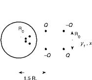
Figure 5. Academic exercise: scattering of a lateral

quadrupole by a cylinder. Two-dimensional equivalent source distribution.

The different ways of posing a problem of aeroacoustics are typically il­lustrated next on the example of the vortex-shedding sound from a circular cylinder in a flow (Fig.1-(a)). For simplicity, the mechanism is described in two dimensions and the incriminated vortex dynamics is reproduced by an equivalent lateral quadrupole close to the cylinder in the near wake, in accordance with Lighthill’s interpretation. The radiation process involves reflection or scattering of the quadrupole by the curved surface of the cylin­der. At subsonic Mach numbers and in view of the vortex-shedding fre­quency f0 ~ 0.2Uq/D where U0 is the flow speed and D is the diameter, the region embedding the cylinder section and the quadrupole is of small extent compared to the acoustic wavelength. The wave equation or the Helmholtz equation becomes locally equivalent to Laplace’s equation. This means that the local acoustic motion can be assimilated to an incompressible potential flow. The sound field of a source close to the circle is obtained by removing the circle and adding two identical image sources : one at the center of the circle and the other one at distance R2/a, where a is the true distance of the source and R0 the circle radius. The resulting configuration is shown in Fig. 5, where the image sources at the center are not shown because they exactly cancel each other. The natural field that would be radiated by the isolated quadrupole in absence of the circle is shown in Fig. 6-(a), where the four expected lobes are clearly identified. Were the quadrupole close to a reflecting plane tangent to the circle, the field would be that of subplot (b), even less efficient. But the true sound as produced by the direct and image sources is much stronger and exhibits the two lobes of an equivalent dipole with orientation normal to the incident flow (subplot (c)). This is explained by the antisymmetric structure of the von Karman vortex street, from which the assumption of a lateral quadrupole is justi­fied. Nearly the same sound field is obtained by just ignoring the direct sources (subplot (d)); the radiating efficiency is explained by the image sources only, in other words by the scattering. The dipole-like behavior is due to the different partial cancellations between the source pairs closest to and farthest from the center. The two-lobed pattern is what would be similarly predicted by the dominant, loading-noise term of Ffowcs Williams & Hawkings’ analogy. Indeed the dominant effect of vortex shedding is an oscillating induced lift on the cross-section of the rod, acting as a dipole. For this the equivalent source will be called a lift dipole. Both problem statements are found equivalent. Since the body is acoustically compact, the interpretation of Ffowcs Williams & Hawkings is better suited because it directly emphasizes the dipolar character of the sound field. Lighthill’s approach in this case shows that the quadrupole behavior of the source is dramatically modified by the reflection on the cylinder. This is because the circular section is a compact body and because the source is very close to it in terms of wavelengths. This fundamental change is more deeply dis­cussed by Howe (2003) using the formalism of compact Green’s functions, not detailed here. It is worth noting that the case of the free-cylinder vortex shedding is very different from the side-mirror image flow. Changing from a symmetric to an antisymmetric flow pattern results in the excitation of a very efficient lift dipole.

Finally all classical statements of the acoustic analogy lead to the defini­tion of equivalent moving sources in a linear wave equation. The sources can be monopoles, dipoles or quadrupoles. The formal solving of the wave equa­tion and the effect of source motion on the radiated field are fundamental aspects, addressed in the next sections.

Penetrable Surfaces and the Extended Analogy

In all applications where the quadrupole term in eq. (3) is significant and must be calculated, which preferentially occurs at high speeds, the computations can be made cumbersome because the sources are distributed within a volume the boundaries of which are not precisely defined. In con­trast, the surface source terms are much simpler to compute and clearly delimited. If CFD must be used in a limited domain surrounding the sur­faces, and if the computations are able to reproduce the acoustic field in the vicinity of its sources, a more convenient way of solving the acoustic problem can be proposed by taking the information not on the physical sur­faces but on a penetrable control surface that can be user-defined at some distance away. This generalized form of Ffowcs Williams & Hawkings’ anal­ogy is widely used in modern Computational Aero-Acoustics (CAA). The continuity and momentum equations are now written as

dt + dx-(pVi) = {po Vsn + p(Vn – Vsn)} r(f) >

д d

dt (pVi) + (pVi V – ) = &vi (Vn – Vsn) – "ij «Л s(f)>

where n = Vf stands for the normal to the control surface and where Vsn = Vs • Vf and Vn = V – Vf are normal velocities. The new expression of Ffowcs Williams & Hawkings’ equation reads

Подпись: 32p dt2 Подпись: (5)2 d2P 52 ( VV i 2 г

c°dX2 = зХ~Щ (p Vi V – aij – CoP^ d

{[pVi(Vn – Vsn) – aij Uj 5(f)}

d

+ ^ {[P0 Vsn + p(Vn – Vsn)] S(f)} and all notations refer to the control surface, again of equation f = 0. Lighthill’s tensor only needs being evaluated outside the surface. Therefore the latter can be chosen in such a way that the quadrupole contribution becomes negligible. In counterpart since the control surface is penetrable, the surface source terms are more complicated than in the standard form of Ffowcs Williams & Hawkings’ equation.

As an example of the methodology, the sound radiated by a rotor operat­ing in free field can be computed from a fixed control surface embedding the rotor, using eq. (5), which seems far simpler than the integration over the
moving blades. But the CFD code applied to get the complete field inside the control surface must reproduce accurately the sound waves generated by the blades or in the vicinity of the blades and their propagation up to the surface, in order to avoid numerical errors. This may be challenging. Finally, the benefit in the solving of the acoustic equation of the analogy is at the price of a bigger computational effort in the simulation of the flow inside the control surface. No way to escape the intrinsic difficulties.

An important corollary of Ffowcs Williams & Hawkings’ formulation with penetrable surfaces is that it can take the non linear processes into ac­count more easily. If sound is generated close to surfaces at a very high level, it propagates initially with significant non-linear aspects. Since the analogy written on the physical surfaces is exact when no approximation is made and since the wave equation is linear, the non-linear mechanisms must be all grouped in the equivalent quadrupole sources; if the latter are discarded from the analysis, the non linearity is ignored. In contrast, non-linear effects are treated implicitly by the CFD code used to solve the internal problem when resorting to a penetrable control surface.

Usual Approximations

Equation (3) is tractable in the usual way if the right-hand side is known independently of any acoustic consideration. The following approxi­mations are generally retained; they can be partially released if the needed information is provided by a CFD code, for instance.

First the Reynolds number of the flow is assumed high and the fluctuat­ing Mach number is assumed low. This leads to Lighthill’s approximation Tj ~ p0 UiUj in which po is the mean density and U stands for the aero­dynamic velocity, cleaned of the acoustic motion. The second source term represents all contact forces, say P, applied from the surfaces onto the fluid, and can be written V – P. It involves both aerodynamic forces and acoustic pressure forces which represent sound scattering effects: P = Paero + p n. In many applications of interest, typically dealing with rotating-blade noise technology, the diffraction effects are ignored. This is accepted for con­venience but only valid as long as the surfaces are acoustically compact. Any surface in a disturbed flow is both a source of sound and a scattering screen. Substantial errors can be generated if the surfaces are not compact anymore. The third term does not require any approximation, since it is

Lighthill’s tensor is now defined by the relative velocity V’ = V — V0, as well as the thickness-noise term involving the surface velocity vector Vs. Furthermore time derivatives are accounting for convection by the mean flow : D/Dt = d/dt + V0 – V.

Ffowcs Williams & Hawkings’ Formulation of the Acoustic Analogy

1.2 The Wave Equation

Lighthill’s equation and alternative forms such as Powell-Howe’s equa­tion are reformulations of general gas dynamics equations which do not address specifically the question of physical boundaries. Yet aerodynamic noise from wall-bounded flows can be predicted from this general back­ground by solving the wave equation together with relevant boundary con­ditions imposed on the wall surfaces. The needed material can be any code or software solving the wave equation, or the Helmholtz equation pro­vided that a Fourier transform is performed to investigate single frequencies. This makes the sources of sound interpreted as distributed quadrupoles in Lighthill’s analogy, and their radiation understood as just scattering by the surfaces. Such a view can be inconvenient if the character of the sources is fundamentally modified by the scattering. Furthermore the formal simplic­ity of the formalism, brought by the homogeneity of the propagation space, is partly lost because of the needed account of boundaries. Another inter­pretation is obtained when replacing the surfaces by additional equivalent sources supposed to radiate in free space, thus extending the original idea of the acoustic analogy. This is the essence of Ffowcs Williams & Hawkings’ formulation (1969) presented now (Curle’s analysis introduced in chapter 1 for a stationary surface can be considered included in this more general one).

The principle is as follows. The physical surfaces are removed and re­placed by mathematical surfaces (Fig. 2). The corresponding inner volume is assumed to contain the same fluid at rest as in the distant propagating medium, whereas the surrounding flow is kept as such. In order to main­tain the discontinuity between the inner volume and the real flow outside, additional sources of mass and momentum must be distributed on the sur­faces. This is achieved by writing the equations in the sense of generalized functions. The continuity equation becomes

chapter 1 and involving the stress tensor aj. Furthermore if the function f is properly scaled the normal unit vector on the surfaces is just Vf = n.

Equation (3) is exact, as a reformulation of the general equations of fluid dynamics. p and Tij are understood in the sense of generalized functions: they are zero inside the mathematical surfaces and equal, respectively, to the density fluctuations and Lighthill’s tensor of the flow outside. Accord­ing to the new statement of the analogy the density fluctuations in the real fluid, in the presence of flow and rigid bodies, are those which would exist in an equivalent acoustic medium perfectly at rest and forced by three source distributions. The first term is responsible for the noise produced by virtue of flow mixing and distortions around the solid bodies. It is just the contin­uation of the quadrupole sources recognized by Lighthill. The second term is a surface distribution of dipoles (divergence of a vector field); it generates what is referred to as loading noise by reference to the aerodynamic loading of a surface in a flow. The third source term involving the time derivative of a scalar quantity is a distribution of monopoles. The resulting acoustic field will be called thickness noise.

The practical use of the formal result is subjected to the same need for simplifications of the source terms as for Lighthill’s equation, if explicit solutions are expected from the general background of linear acoustics. The simplifications are summarized in next section.

Basic Mechanisms – External Flows

Major noise generating mechanisms from external wall-bounded flows are introduced and described shortly in this section. Phenomena associated with thermal conductivity are discarded so that the analysis is focused on mechanical aspects. Complementary developments should be considered for internal flows and/or combustion problems, as discussed in chapter 1. The different ways the mechanisms can be simulated or modeled for the sake of noise predictions in the far-field will be addressed in subsequent chapters.

The first fundamental principle to be retained from everyday life ex­perience is that vortex dynamics makes sound. This implies two major mechanisms. First, sound is generated as free vortices interact mutually: this occurs in any turbulent mixing region such as a free jet or a turbulent boundary layer over a smooth boundary. Secondly, sound is generated as vortices interact directly with a geometrical singularity of a solid surface, such as a sharp edge, a corner, an excrescence or any accident. The sec­ond mechanism is much more efficient, as easily understood for instance by putting a knife blade in the jet of a pressure-cooker valve and hearing the difference in radiated sound level.

Examples shown is the chapter are just specific declinations of the same process. They are mostly related to a broadband noise signature since a

Подпись: (c)

Basic Mechanisms - External Flows
Подпись: (a)

(d)

Figure 1. Generic turbulent flows responsible for broad­band noise generation, illustrated by instantaneous 3D pat­terns (a, c, d) and 2D vortical trace (b). (a): vortex-

shedding from a cylinder; (b): trailing-edge scattering of a turbulent boundary layer; (c): combined trailing-edge scat­tering and vortex shedding; (d): combined vortex-shedding and turbulence impingement on an airfoil. From Moon et al (2010) (a), Wang et al (2009) (b), Chang et al (2006) (c) and Jacob et al (2002).

turbulent flow is the origin of the sound generating process. Sound can also be radiated when a solid surface is moving through the air in an acceler­ated, periodic motion, as shown in section 5.4. This specific mechanism is typically involved in the tonal noise of rotating blades, not addressed in this book.

Typical unsteady vortical flows attached to solid surfaces and generating broadband or narrow-band noise at relatively moderate-to-large Reynolds numbers (in the sense that the flow regime is definitely turbulent) are illus­trated in Fig. 1-a-to-d from Moon et al (2010), Wang et al (2009), Chang et al (2006) and Jacob et al (2002). All pictures are deduced from validated Large-Eddy Simulations (LES), either compressible or incompressible. They only illustrate the vortex dynamics responsible for sound production, not
the sound itself. The vortex-shedding mechanism (Fig. 1-a) produces the Aeolian tones heard when the wind is blowing on mechanical structures. The noise produced by trailing-edge scattering (Fig. 1-b) is important for all rotating-blade technologies, especially for wind turbines. Both may be produced together in the case of blunted trailing-edges (Fig. 1-c). The two – body configuration of Fig. 1-d is a first step toward the investigation of more complicated ones, such as the high-lift devices of an aircraft wing. In this case, the impingement of the vortical patterns shed from the first body onto the second one is generally much noisier than the vortex shedding itself. The first three cases are mechanisms of what is called the self-noise of a solid surface in a flow. The fourth one illustrates the turbulence-impingement noise of an airfoil. Both that noise and trailing-edge noise will be addressed specifically in chapter 5.

Going into the details, the faster the inertia variation in a vortical flow is, the more efficient is the acoustic dissipation. This makes sound production much stronger in the vicinity of singular points on a solid surface, such as leading or trailing edges of blades, slots or bumps on surfaces, and so on. For vortex-shedding noise, the dominant unsteady vortical motion takes place downstream in the very near wake. The rapid inertia variation is precisely in the formation of the vortices. As a result the source domain is the immediate vicinity of the cylinder. Trailing-edge noise is due to the rapid re-arrangement of boundary-layer turbulence as it is convected past the edge; this is why the efficient source region is a limited area around the trailing edge. The same holds in configuration (c) for both incriminated mechanisms. In case (d) the dominant source region is the more or less extended vicinity of the airfoil leading edge.

Previous examples refer to bodies of limited extent with respect to the acoustic or aerodynamic length scales. But boundary-layer flows developing on the walls of elongated bodies also generate sound. It is well accepted that a developed turbulent boundary layer over an extended and smooth surface such as a rigid flat plate is not an efficient sound generator because of its dominant quadrupole nature, as pointed out by Goldstein (1976). In contrast the aerodynamic sound is much higher if the surface exhibits a geometrical singularity. Therefore cavities, slits, excrescences or steps appear as localized sources of noise. This will be discussed in section 2.5.

Pictures of Fig. 1 together with aforementioned arguments stress that the dominant sources are quite localized around the surface edges and that vortex dynamics farther away in the wake is a minor contribution. With respect to a distant observer the unsteady flows act as equivalent moving sources radiating in the surrounding medium. The prediction methodology subsequently developed is in two steps; one is the description of the equiva­lent sources, the other one is the description of the propagation itself. Both are detailed in next sections.

Aerodynamic Noise Generation – Reminder of Basic Principles

1.1 Introduction

Aerodynamic noise radiation from an unsteady flow is a dissipation mechanism by which a tiny part of the mechanical energy of the flow is con­verted into sound. The particularity of this acoustic dissipation in open-air aeroacoustic problems is that it propagates at large distances and contam­inates the environment. Moreover the acoustic dissipation rate of aerody­namic noise is a very rapidly increasing function of the characteristic Mach number. Yet it is at a much lower order of magnitude than other forms of

R. Camussi (Ed.), Noise Sources in Turbulent Shear Flows: Fundamentals and Applications, CISM International Centre for Mechanical Sciences, DOI 10.1007/978-3-7091-1458-2_2,

© CISM, Udine 2013

dissipation such as viscous losses. This makes the points of view of Fluid Dynamics and of Aeroacoustics differ. In absence of acoustic back-reaction, a flow can be most often described ignoring its acoustic dissipation, for what enters the scope of mechanical efficiency, losses, fuel consumption, and so on. In contrast describing the acoustic field requires a much higher level of accuracy. This remark holds for all unsteady flows encountered in aero­nautics, turbomachinery, heating and ventilating engineering and ground transportation. More precisely the scope of this book reduces to the basic sound generating mechanisms which develop around bodies in translating motion because of some unsteadiness in the flow, provided by turbulence or instabilities.

As mentioned in chapter 1, the pioneering work of Sir M. J. Lighthill in the fifties (1952) addressing the problem of turbulence noise is generally considered the starting point for the investigation of aerodynamic noise. This work was next extended by Ffowcs Williams & Hawkings (1969) to include the presence of moving bodies in a flow. The basic idea is to define an acoustic analogy, by which the real problem involving a highly disturbed flow and moving solid surfaces is restated as a problem of linear acoustics in an unbounded uniform medium with some equivalent acoustic sources. The difficulty of solving exact, non-linear equations is then apparently avoided and replaced by the question of defining the equivalent sources. A crucial point is that there are different ways of deriving a wave equation from the equations of gas dynamics, leading to various analogies. Any analogy is based, first on the choice of the field variable the wave equation will gov­ern, and secondly on the wave operator itself. Lighthill’s formulation and subsequent developments resort to the classical wave operator acting on the fluctuating density recognized as the relevant acoustic variable. Other choices can be proposed, each leading to a different definition of the equiv­alent source terms. Anyway, the difficulty inherent to the equations of gas dynamics cannot be escaped by just writing the equations in another way. The pseudo-wave equation of the acoustic analogy cannot be solved exactly because generally the equivalent source terms still include contributions of the field variable to be determined : the equation and the source terms are said implicit. Therefore the advantage of the formalism is enlightened only if simplifying assumptions are accepted, for instance making the source terms explicit by removing the acoustic field variable from them. This has the effect of discarding some part of the physics. The resulting approach is an interpretation. It is fruitful whenever the neglected phenomena are of secondary importance and the dominant mechanism is preserved in the process. Furthermore the degree of simplification of the source terms can also be a matter of available means of describing the flow. Finally different analogies are more suited in different practical problems, as already pointed in chapter 1. Because the interest of an acoustic analogy is to benefit from the formal simplicity of the standard Green’s function solving procedure, the classical wave equation was preferred historically. Ffowcs Williams & Hawkings’ formulation presented in this chapter and extensively applied in the aeroacoustic community obeys this strategy. But the idea of the analogy can be extended to more general propagation operators. Such extensions, more especially dealing with jet-noise applications, are described in subse­quent chapters.

It must be stated clearly that the aim of an analogy is not essentially to provide very accurate results, but rather to infer general laws from the standard procedures associated with the classical wave equation. This may be sufficient to achieve low-noise design in engineering applications. How­ever, a preliminary knowledge of the main flow features must be already available, either from experiments, Computational Fluid Dynamics (CFD) or theoretical considerations. What is the degree of required accuracy in the flow variables to get satisfactory acoustic results will be one of the key issues when applying the method. In other words tell me the flow I will tell you the sound.

Sound Radiation by Moving Surfaces and the Green’s Functions Technique

Michel Roger

Ecole Centrale de Lyon

Abstract

The present chapter is dealing with some fundamentals of sound radiation from rigid moving bodies or bodies in a flow. The theo­retical background of the analogy is reminded in a first part. Ac­cording to Ffowcs Williams & Hawkings’ formulation the problem of sound generation by unsteady flows in the presence of solid sur­faces is restated as a problem of linear acoustics with equivalent moving sources. Therefore the solving procedure is based on stan­dard Green’s function technique. This procedure is detailed in the second part as a necessary background and source motion is con­sidered a key feature of the radiation. Aspects inherent to the wave operator and specific aspects of acoustic sources on the one hand, and source physics and source motion on the other hand, are ad­dressed separately for the sake of physical understanding. In the third part formal developments and dimensional analysis of Ffowcs Williams & Hawkings’ equation are proposed, both to highlight the flow features involved in sound generation and to point out the ef­fects of motion. Some introductory topics have been presented in chapter 1 and are re-addressed for specific purposes.

The “Voice of the Dragon”

Corrugated pipes (Figure 23) are locally rigid and globally flexible. This makes them very useful for many applications ranging from vacuum cleaner tubes to risers for offshore natural gas production. A problem is, however, that flow through such pipe can cause severe whistling. Actually, a plastic

The “Voice of the Dragon”

Figure 23. Corrugated pipe used as musical toy.

corrugated pipe of a length of L = 80 cm and an inner diameter D = 3 cm is commonly used as a musical toy called: hummer [Silverman and Cush­man (1989)]. In musical applications this toy is called: the ”Voice of the Dragon” [Silverman and Cushman (1989)]. Holding one open end of the tube in the hand and swirling the tube above the head produces a melodic sound with increasing pitch as the angular rotation velocity Q increases. This tube is actually a centrifugal pump. Due to centrifugal acceleration Q2r there is a pressure gradient dp/dr = —p0Q2r along the tube, where r is the distance from the (non moving) open end. At the moving open end of the tube the outflow forms a free jet due to viscous flow separation. This free jet implies that the pressure at this open end is close to the atmospheric pressure po. Hence the pressure at the opposite (non moving) open end is p(0) = p0 — 1 p0Q2L2. In the inflow from the surrounding to the fixed inlet, we can apply the Bernoulli equation p(0) + 2p0U2 = p0 from which we con­clude that in first order approximation U = QL [Nakiboglu et al. (2012)].

The flow along the corrugations can be seen as a grazing flow along a shallow cavity. The cavity depth H is so small (order of a few millimetres) that we can in first approximation neglect the compressibility of the air in the cavity. The shear layer formed along the opening of the cavity is unsta­ble. The whistling is caused by coupling this instability to a longitudinal acoustic wave along the pipe. The acoustic modes of the pipe have frequen­cies predicted by fn = n(ceff /2L) (n = 1, 2, 3) where the effective speed of sound along the pipe is:

c‘"=с°Ш (196)

Were Vin = nD2L/4 is the inner volume excluding the cavities of the cor­rugations and Vtot is the total volume of the tube including the cavities.

The critical Strouhal number SrW = f (W + rup) for whistling based on the cavity width W plus the upstream edge radius of the cavities rup appears to be a function of W/D. As shown in figure 25 SrW varies from

The “Voice of the Dragon”

Figure 24. Sound power produced by a cavity in a corrugated tube as a function of the Strouhal number [Nakiboglu et al. (2011)].

0.8 to 0.3 as W/D varies from 1 to 0.05. In an attempt to explain this variation Nakiboglu et al. (2011) considered incompressible 2-D axial sym­metric flow simulations of a single cavity along a tube. These simulations have been carried out with a commercial code. In the model Nakiboglu et al. (2011) imposes, at a distance D/2 upstream of the cavity, a steady flow profile corresponding to the time average of the fully developed turbulent flow profile through a corrugated pipe. This can be calculated by using a steady RANS (Reynolds Average Navier Stokes) calculation or it can be measured. A harmonically oscillating uniform (over the cross section) veloc­ity representing the acoustic plane wave is superposed on this time average profile. The fluctuation in the difference in total enthalpy AB’ over the cavity is calculated. The difference of total enthalpy AB’ref calculated for the same boundary conditions across a reference straight tube segment is
subtracted AB’ — AB’ref. The acoustic power generated by the cavity is then calculated by using vortex sound theory:

< P >=< po(AB’ — AB’ref )u’ > . (197)

Figure 24 shows the results obtained for this acoustic power at fixed am-

plitude u’/U as a function of Srw = f (W + rup)/U. The maximum of the predicted power is assumed to correspond to the critical whistling Strouhal number (Figure 25). As explained by Nakiboglu et al. (2011) the decrease of SrW with increasing D/(W + rup) is acually due to the change in ratio of boundary layer thickness and cavity width. The same effect has been reported by Golliard (2002), Kooijman et al. (2008) and Ma Ruolong et al. (2009).

We observe an almost perfect agreement between theory and experi­ments (Figure 25). The prediction of the whistling amplitude using this model appears to be less successful [Nakiboglu et al. (2011)]. The model overestimates the source power by about a factor of two.

Another interesting fact is that a laminar model was used to predict the dynamic response of a turbulent flow to acoustic forcing. This approach has already been used in many papers such as the work of Michalke (1965) and Mery and Casalis (2008). However, we do provide at this point any explanations for the success of the quasi-laminar method. This calls for further research.

The “Voice of the Dragon”