Category Principles of Helicopter Aerodynamics Second Edition

Other High-Speed Concepts

Most of the major US helicopter manufacturers have undertaken studies of high­speed rotorcraft concepts. Similar studies have been conducted by some European manu­facturers. The general requirements call for a rotorcraft capable of efficient hover capability that can cruise at over 400 kts, which is about twice as fast as is attainable with a conventional helicopter. Most concepts would be classified as convertible aircraft or convertiplanes. The primary advantage of any convertiplane concept is the ability to balance efficient hovering flight capabilities with efficient cruise and good range but without incurring large weight and cost penalties. Despite much research, there is no other high-speed or convertible ro­torcraft concept currently flying other than tilt-rotors. Some of the high-speed rotorcraft designs considered have included the following:

1. The ABC concept: In the 1960s, Sikorsky Aircraft announced the XH-59A research aircraft using the Advancing Blade Concept (ABC). This was a compound con­cept with auxiliary propulsion and a rigid coaxial rotor system that was designed to alleviate the problem of retreating blade stall by allowing a more symmetric distribution of lateral airloads over the rotor disk. Chaney (1969) gives a good overview of the aerodynamic issues. During flight testing, the machine reached a maximum speed of 263 kts (487 kph). For the time, it was the only rotorcraft to have approached such speeds without lift compounding.

2. The X-wing concept: This design employs a unique rotor system that uses circula­tion control. The blades consist of thick elliptical airfoils, and air is blown at high velocity out of the leading or trailing edges to create lift by means of the Coanda effect – see Cheeseman (1968) and Williams (1976). A complicated pneumatic blowing system was required for cyclic blowing in forward flight. As airspeed built, the rotor system was designed to be slowed down and stopped, forming an X-wing configuration. The full-scale rotor was tested in a wind tunnel in the early 1980s, but it was never flown because of various technical issues and escalating costs.

3. The variable diameter rotor concept: This is another Sikorsky concept, which looks similar to a conventional helicopter but the blades telescope in length during flight to increase or decrease the disk area. The design is discussed by Fradenburgh et al. (1973) and Fradenburgh (1992). A system of clutches inside the rotor hub controls the extension and retraction process. This technique allows for low rotor disk loadings and maximum efficiency in hover, whereas the smaller diameter rotor allows for a higher cruise efficiency. A similar design has been considered for a tilt-rotor, where the rotor diameter is reduced for airplane mode – see Studebaker & Matuska (1993). The system has been successfully flown in the wind tunnel but not yet on a full-scale aircraft.

4. Rotor-wing concept: This is a high solidity stoppable rotor system with three blades. The rotor is slowed down and stopped in forward flight, with two blades pointing upstream forming forward swept wings, whereas the third blade points downstream and lies over the fuselage. The concept is similar to the ill-fated X – wing circulation-controlled rotor of the 1980s. See Rutherford et al. (1993) for a history of such stopped rotor designs.

5. Quad tilt-rotor: A quad tilt-rotor concept has been proposed in 1999 by Bell with a fuselage the approximate size of a large fixed-wing cargo airplane. Design features of the quad tilt-rotor include the use of two wings, one forward and one aft. Each wing has an engine and proprotor mounted at its tip. The civil version of the concept has been designed to carry up 100 passengers at 300 kts.

6. Folding, stowed, or trailed rotor systems: In this concept the rotor is stopped, the blades folded back into the fuselage, and the lift is transferred to fixed wings. Various aeroelastic effects are possible during the stopping and stowing process and these are difficult to contend with; see Celniker et al. (1965) and Deckert & McCloud (1968). The high capital and maintenance costs of the system, as well as the high weight of the folding and blade storage system, means that this type of machine is not a particularly attractive design option.

7. Shrouded rotor designs: The idea here is to use a relatively large ducted fan, in­tegral to a wing, to provide the vertical lift. As the aircraft gains speed, power is transferred from the fan to pure propulsion, shutters cover the fan, and the wing provides all the lift. The concept, however, is not new, having being used on the Ryan XV-5 in the 1960s. This aircraft demonstrated successful transi­tions from hover to forward flight and back, flying at speeds of up to 330 kts (577 kph).

8. Slowed rotor concepts: By reducing rotor rpm in flight, this alleviates compress­ibility effects on the advancing blade and allows higher flight speeds. However, all rotor systems experience a loss of flapping rigidity with reduction in rotor rpm, so only about a 20-30% reduction in rpm seems possible before aeroelastic issues become critical. Nevertheless, some aerodynamic benefits at very high advance ratios seem possible, including better rotor lift-to-drag ratios. See also Celniker etal. (1965).

9. Gyroplane concepts: The gyroplane concept takes advantage of the vertical takeoff capabilities of the helicopter but the higher speed of a compound but with the rotor operating in the autorotative state. The ideas were explored in the 1950s by McDonnell with the XV-1 and by Fairey with the Gyrodyne and Rotodyne (see page 715). One advantage of a gyroplane is reduced capital and operating costs compared to a conventional shaft driven helicopter. It would appear that renewed interest in this concept may lead to its further development in the twenty-first century.

10. Morphing concepts: There have been many convertiplane concepts proposed over the years. More recently, the Mono Tilt-Rotor (MTR) has been proposed as an innovative convertiplane concept. Its capabilities are predicated on the combina­tion of a single coaxial rotor system and sophisticated kinematics that morph the aircraft topology for efficient flight operations. As yet only developed in concep­tual form [see Preator et al. (2004)], the MTR design fully integrates an efficient coaxial rotor, a folding lifting wing system and a cargo handling system that is capable of rapidly and economically moving different types of mission tailored payloads.

Tilt-Rotors

Based on Bell’s experience with the XV-3 (see page 48), the Bell XV-15 tilt-rotor was designed and first flown in 1977. It has proven a reliable research aircraft, from which much knowledge has been gained about tilt-rotor technology. The much larger V-22 tilt – rotor (Fig. 1.40) flew in 1989 and in 2005, after a lengthy development phase, it was in low-rate production. The V-22 is designed to fullful many of the missions that are possible with a conventional helicopter, but with the added advantage of much higher flight speed capability. However, it must be borne in mind that the tilt-rotor design is a hybrid, and a performance compromise, between a helicopter and a conventional airplane. The Agusta – Bell Model 609 tilt-rotor was designed in the late 1990s for the civilian market.

The aerodynamic design of the tilt-rotor poses many additional challenges over that of the conventional helicopter. The smaller rotor diameter means that in hover the disk loadings of a tilt-rotor are much higher than those of a helicopter of the same gross weight. The efficiency of the rotor is also lowered because of the very high blade twist, a feature required to ensure good propulsive efficiency in airplane mode. In addition, when in hover the wings of the tilt-rotor operate in the downwash from the rotors, which produces a large download on the aircraft and decreases the payload it can carry. The fixed wings also influence rotor performance, and the combined effect degrades the hovering efficiency (figure of merit) compared to a helicopter of the same gross weight – see McVeigh et al.

(1991) . Various techniques are used to minimize these interactional aerodynamic effects, including 90-degree deflections of the wing flans — see Stepniewski & Keys (1984) and Wood & Peryea (1991). In fixed-wing mode, when the rotors act as propellers, they are rather less efficient because the disk loading is too low and profile losses are higher than would be achieved with a conventional propeller. Rosenstein (1986) and McVeigh et al.

(1997) give good overviews of the numerous aerodynamic design trade-offs for tilt-rotors.

The tilt-rotor has two sets of flight controls, one set for helicopter mode and another for fixed-wing mode. In helicopter mode, the rotors of a tilt-rotor are controlled with normal cyclic and collective pitch controls. Yaw is controlled by differential cyclic, just like a tandem rotor machine such as the CH-47. During transition from helicopter mode to fixed – wing mode, the aerodynamic environment encountered by the rotors becomes extremely complex and high airloads can be produced. The relationship between the airspeed and the rotor tilt angle must conform to a relatively narrow envelope for safe operation and this is controlled with the aid of the fight control system. In airplane mode the rotors act as conventional propellers, with all of the vertical lift forces being produced by the wing. In this mode, control is achieved with the use of conventional aerodynamic surfaces, namely the flaperons, elevator, and rudder. Despite the complexity and high costs of the tilt-rotor it has the potential to play a unique role in vertical flight aviation that a conventional helicopter cannot. It has not yet, however, advanced to the level of military or civil success enjoyed by the modern helicopter.

High-Speed Rotorcraft

Подпись:

High-Speed Rotorcraft

VprtiPiil lift aircraft tbot іюа г»лтплппЛ|п У vlUvui mi uiiviuu uiui uov wui^vuiiulii

are referred to as high-speed rotorcraft. Not only are these aircraft capable of vertical takeoff and landing, but they can attain much higher speeds than conventional helicopters. They are, however, not necessarily more efficient (say, in terms of effective lift-to-drag ratio) nor are they as economic because they generally always have a higher empty weight fraction (i. e., lower payload), as well as higher capital and operating costs.

1.10.1 Compound Helicopters

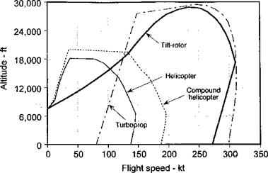
A compound helicopter involves a lifting wing in addition to the main rotor (lift compounding) or the addition of a separate source of thrust for propulsion (thrust com­pounding) – see the review of Lynn & Drees (1967). The idea is to enhance the basic performance metrics of the helicopter, such as lift-to-drag ratio, propulsive efficiency, and maneuverability. The general benefit can be an expansion of the flight envelope compared to a conventional helicopter (see Fig. 6.38). While there are no compound helicopter de­signs in current production (although many prototype designs have been built), except for some of the Russian designs that may have an element of lift compounding, most helicopter manufacturers at one time or another have investigated auxiliary propulsion or lifting wings to off-load the rotor and expand the flight envelope. However, there are major drawbacks in this compound design in terms of increase in empty weight and loss of payload capability, download penalties in hover, reduced vertical rate of climb and higher operating costs.

One of the first experimental compound helicopter designs was the McDonnell XV-1. This was a pressure jet driven rotor, with a wing and a pusher propeller. After a vertical takeoff, the power was shifted from the tip jets to the propeller and the rotor continued to turn in autorotation. In 1954 the aircraft was flown at speeds approaching 175 kts (201 mph,

High-Speed Rotorcraft

Figure 6.38 Representative speed-altitude flight envelopes of a conventional helicopter versus a compound design, a fixed-wing turboprop, and a tilt-rotor.

324 km/h). The Sikorsky NH-3A was based on the S-61 and used a wing mounted with two turbo-jets for auxiliary propulsion. It achieved speeds of up to 230 kts (265 mph, 388 km/h) – see Fradenburgh & Chuga (1968). The Bell UH-1 compound also had a wing and two turbojets and reached a speed of 275 kts in level flight. The Fairey company built a number of tip-jet driven compound machines, with the last and largest being the Rotodyne (see

пяор. 71 S’i This Ч’З ООП Ih ( S 000 ]co яіггтяЛ was пола/ргргі hv two tnrhnnrnns whirb яісп

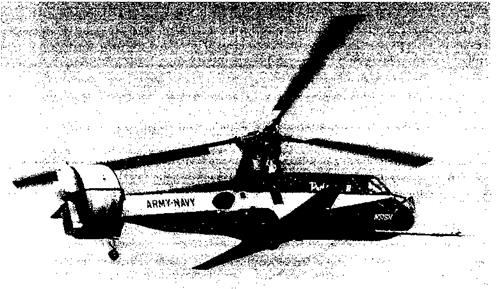
supplied compressed air for the tip jets. In 1959 the machine set a world speed record in its class of 167 kts (192 mph, 309 km/h). The Piasecki Pathfinder (Fig. 6.39) was a compound

High-Speed Rotorcraft

Figure 6.39 The Piasecki Pathfinder was a successful compound helicopter concept from the 1960s but it remained in the experimental phase.

that used a rotor off-loaded by a small, low-mounted fixed wing when the craft transitioned into forward flight. The ducted fan (“ring-tail”) at the tail, with vertical vanes in the duct, provided anti-torque and directional control. The 16H-1A Pathfinder II was a bigger and more powerful version, with a cabin large enough for eight seats. This machine reached level flight speeds of 195 kts (224 mph, 361 km/h). This US Navy and US Army evaluation program provided a wealth of valuable information on compound rotorcraft technology and operations, much of which was later used in the development of the Lockheed AH-56 Cheyenne (Fig. 1.39), which used a wing and a pusher propeller mounted to the tail. Today, the Piasecki Company continues to examine compound helicopter concepts. In the early 1970s, Boeing-Vertol flew the tandem Model 347 with relatively large wings, the technical motivation for which is discussed in detail by Stepniewski & Keys (1984).

The ideas of compounding have received renewed attention by some manufacturers, with some revived ideas being discussed by Humpherson (1998). Orchard & Newman (1999a, b; 2000) have considered some of the unique design issues associated with the optimization of a modern compound helicopter concept. It remains to be seen, however, if the compound helicopter design will reemerge as a viable rotating-wing design concept for the twenty-first century.

NOTAR Design

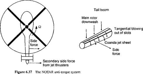
The use of jet thrust for anti-torque is not a new one, having been used on the Cierva-Weir W-9 in 1945 and also in other designs. However, the design required high power and directional sensitivity was poor. The idea was also used on prototype helicopters built by Hiller in the US and Nord in France. The NO TAil Rotor or NOTAR concept uses a similar yet different approach to anti-torque and yaw control. The design is discussed by Logan (1978) and Sampatacos et al. (1983), and is reviewed by Winn & Logan (1990). Here, anti-torque capability comes from a circulation control concept, which results in a distributed side-force along the entire tail boom assembly. As shown in Fig. 6.37, a high – velocity jet (or jets) of air from a pressurized tail boom is blown tangential to the surface out of narrow slots that run lengthwise on one side of the tail boom. In combination with the downwash velocity produced by the main rotor, these jets cause the flow to remain attached to the tail boom surface by means of the Coanda effect. Downstream of the slots, a powerful suction pressure is produced on one side of the tail boom and a side (anti-torque) force results. The magnitude of this side-force depends on the jet velocity out of the slot. This is controlled by adjusting the pressure inside the tail boom by means of a variable pitch fan and compressor. A small auxiliary nozzle at the end of the tail boom provides a pressurized jet to improve yaw control rates and overcome the inherent lag in the circulation control system. The nozzle in the jet thruster is rotated by the conventional action of the pilot’s foot pedals.

In forward flight, the circulation control becomes less effective as the main rotor down – wash moves further along the tail boom. Fixed aerodynamic stabilizers and the jet thruster
combine to produce the necessary anti-torque and yaw control. The NOTAR concept has proved attractive to operators because of its low noise, safety for ground personnel, and freedom from blade strikes when operating in confined locations. Also, for a military heli­copter this system is attractive because of the absence of a vulnerable tail rotor assembly, and it has a high level of redundancy in the event of any tail boom damage.

Other Anti-Torque Devices

Besides the conventional tail rotor, other types of anti-torque devices are used on modem helicopters. These are the fenestron (or fan-in-fin or fantail) and the NOTAR concepts. All have relative advantages and disadvantages compared to a conventional tail rotor.

6.10.1 Fan-in-Fin

Shrouded or ducted fan anti-torque designs, which are known as “fenestrons,” “fan- in-fin,” or “fantail” designs, have been frequently considered over conventional tail rotors, especially for smaller and lighter helicopters. A photograph and schematic of a fan-in-fin design is shown in Fig. 6.35. Details of the design of such anti-torque devices are given by Mouille (1970, 1979), Mouille & Dambra (1986), Vuilet & Morelli (1986), Vialle & Amaud (1993), and Abrego & Bulaga (2002). Fan-in-fin designs typically are found to have lower power requirements than an open tail rotor to produce the same amount of thrust. Alternatively, this means the fan-in-fin design can give the same anti-torque and yaw authority with a smaller and perhaps lighter design compared to a conventional tail rotor. See also Davidson et al. (1972) for the design trades.

Vertical fin

Other Anti-Torque Devices

Figure 6.35 The fan-in-fin or fenestron tail rotor, as used on the SA-365 Dauphin.

w = vJa,

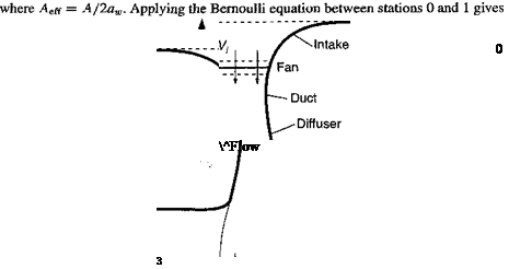
Подпись: WFigure 6.36 Flow model assumed for fan-in-fin analysis using momentum theory.

The theoretical analysis of the ducted rotor (propeller or fan) has been approached by Kruger (1949) and Kuchemann & Weber (1953), with experimental work by Mort (1965), and Mort & Gamse (1967). The momentum theory discussed in Chapter 2 can be extended to the analysis of a fan-in-fin design, with the flow model being shown in Fig. 6.36. Far upstream of the fan, the velocity can be assumed to be zero. At the plane of the fan, the induced velocity is u( . By the principle of conservation of mass, the mass flow rate, m, is constant through the system so that

m = pAvi = p(awA)w, (6.40)

where, by virtue of the duct design the area of the slipstream flow at the outlet is awA with the velocity at the duct outlet being w and with aw being a wake contraction parameter. This gives the relationship that w = Vi/aw. By means of conservation of momentum the thrust on the duct and fan is

Подпись:T = 7duct + 7fan = mw = (pAvj)w =————–

aw

or

Other Anti-Torque Devices

Other Anti-Torque Devices

(6.42)

Подпись:Po = Pi + – pvf,

and between stations 2 and 3 gives

Other Anti-Torque Devices(6.44)

Using Eqs. 6.43 and 6.44 gives for the thrust on the fan:

Other Anti-Torque Devices(6.45)

Using Eqs. 6.41 and 6.45 gives

Подпись: (6.46)Подпись: (6.47)Подпись:Tfan _ {pAw2 _ W _ 1

T pAviW 2 Vi 2 aw

Using Eqs. 6.42 and 6.46, we obtain the induced power consumed by the fan:

( T fcF Г3/2 (Pi) fan = TfnVi = — = —====

2awJV pA y/AawpA

(fi)fan

(Pi)rR

where (Рі)тя refers to a conventional (unducted) tail rotor. The latter equation gives an interesting result, in that it shows that if the shape of the duct is controlled so that the rotor wake does not contract as much as would occur naturally with a conventional tail rotor (for which in the ideal case, aw = 0.5, Aeff = A), less power will be required to produce a given total thrust. In the case where aw — 1 (the assumption of no wake contraction so that Aeff = A) a ducted fan of the same area will consume jpl of the power of a conventional tail rotor (i. e., 30% less power for the same net thrust). Alternatively, a ducted fan of half the disk area of a conventional tail rotor (i. e., a diameter reduced by a factor l//2) will produce the same thrust and consume the same power. Generally, however, because the length of the duct must be relatively short to minimize structural weight and drag penalties in forward flight, the potential gains in efficiency are not as large as suggested by the above analysis. Losses introduced by drive shafts also reduce any potential gains in efficiency. However,

4-It Л 1 ЛІ V!/>«• 1/ЧЛЛ л4¥/л<-л Л Л ПЛ/Ч1 (if r«4 TTHfL n 1 1Л Г 4/401 /VM /VII Г/4 n A1 »4І4 Q«" /-lll/tfl 1-4*4 ■■

ню luwti tip-uj&a diccta d^duudi&u vvitii a lau-iii-un givt; a iuivu^i ltuuuuuu ш induced power requirements. Overall, the fan-in-fin design offers some overall advantages compared to a conventional tail rotor for anti-torque and directional control.

The fan rotor design may also be approached from the principles of the blade element momentum theory (BEMT) discussed in Section 3.3. Equating the contributions to section thrust made from the momentum and blade element theories (using Eqs. 3.45 and 3.57), then we can write for the ducted fan that the incremental thrust is

2 1

dCj = —A2rdr = – crCir2dr, (6.49)

О-w 7

Other Anti-Torque Devices Other Anti-Torque Devices Подпись: (6.50)

where the mass flow through the duct and fan is controlled by the effective wake contraction ratio aw. This is a function of duct design as well as the gap between the fan blades and the duct. Stator vanes are usually used to straighten the outlet flow and recover swirl losses, which are higher because of the higher rotor rpm. With the assumption for a value for aw (a common assumption for a fan is to use aw=1.25), then the inflow X can be solved by finding a solution to a modified form of the inflow equation, namely

Clearly, the optimum blade twist for a fan is of the same hyperbolic form needed for an unducted rotor. In some cases fan rotor designs may have large blade twist angles compared to a conventional tail rotor, and it may be inadequate to assume small angle approximations to find X. In this case the inflow equation can be solved numerically. Starting from Eq. 6.49 then the inflow distribution over the disk can be found using

Подпись: (6.51)X(r) = – y/awo(Ci cos ф — Cd sin0)r/4.

Because Ci and Q are functions of the blade section angle of attack, 9 —ф, which is in turn a function of X at each section, then the foregoing equation must be solved iteratively. Con­vergence, however, is found to be rapid. Thereafter, the sectional airloads can be determined and net rotor thrust and power follows by radial integration along the blade.

In forward flight the fan-in-fin is shielded from the external flow and the main rotor wake and, consequently, its performance is usually more predictable. Although as shown by Basset & Brocard (2004), even here empirical corrections to the momentum theory approach must be used because of the streamline inlet distortion produced by the duct. The vertical fin surrounding the fan is designed to provide a side force in forward flight and so most of the anti-torque. The aerodynamics of “sense of rotation” and the interference effects of the fin assembly, which are important for conventional tail rotors, are less important for the fan-in-fin design. However, the possibility of flow separation at the inlet lip of the shroud must be kept in mind, and usually the lip is carefully contoured to avoid such effects. Flow separation at the inlet to a ducted fan-in-fin can lead to a loss of thrust and/or thrust fluctuations that is consistent with some loss of effectiveness as a directional control producing device (instantaneous thrust) although not necessarily as an anti-torque device (average thrust).

From a safety perspective, the shrouded nature of the fan-in-fin reduces the possibilities of blade strikes during low-altitude flight operations and also the risk of injury to personnel on the ground. The larger number of blades on a fan-in-fin design increases the frequency of the rotor noise and this can appear in the helicopter noise spectrum over a range of frequencies to which the human ear is more sensitive. However, at greater distances these higher frequency sounds are more readily absorbed in the atmosphere. Efforts to reduce the noise of fan-in-fin designs through phase modulation using unequal blade spacing have made the fan-m-fin sound subjectively less noisy — see Vialle & Arnaud (1993).

Representative Tail Rotor Designs

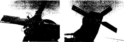
Examples of modem tail rotor assemblies are shown in Fig. 6.34. Some tail rotors may be very simple two-bladed teetering assemblies (e. g., Fig. 4.20), whereas others may be relatively sophisticated bearingless or hingeless designs. Common amongst all tail rotors is the lack of any cyclic pitch; only collective pitch is used because control of the tail rotor disk orientation is not required. Nevertheless, the tail rotor must be provided with flapping so that the blades may be allowed to respond to the changing aerodynamic environment. Lead-lag hinges are not used to save weight and reduce mechanical complexity. Instead, a large amount of <S3 or pitch-flap coupling is built into the tail rotor design. This provides a means of allowing the blades to pitch cyclically in such a way as to minimize blade flapping produced by the changing aerodynamic loads (see Section 4.12). In addition, a set of preponderance weights may be attached to the tail rotor pitch horns. These are a set of weights that lie out of the plane of rotation and rely on centrifugal forces to help keep the

(a) Four bladed tractor (UH-60) (b) Four bladed pusher (AH-64)

Representative Tail Rotor Designs

Figure 6.34 Representative tail rotor assemblies (a) UH-60 bearingless tail rotor, (b) AH-64 twin teetering tail rotor

control forces to within manageable limits. Preponderance weights are usually only found on tail rotors that use highly cambered airfoil sections so as to help minimize moments transferred to the pitch control system.

Design Requirements

As for the main rotor, the power required to drive the tail rotor depends on the disk loading. Whereas a larger diameter may be preferable for low induced power requirements,

this is outweighed by several factors. First, a larger diameter usually means a heavier design and this is undesirable, mainly because of adverse effects on the helicopter’s center of gravity location. Second, to meet certification requirements it is usually desirable that the tail rotor disk loading and induced velocities be high enough so that sideward flight of at least 35 kts is possible without the tail rotor entering into the vortex ring state. Both of these constraints dictate the use of a relatively small tail rotor with a high disk loading.

Tail rotors typically have two or four blades, and it has been shown in Section 6.4.4 that for a rotor there is no particular aerodynamic advantage of one number over the other. Only collective pitch is required because there is no need to control the orientation of the tail

rr»trr HioV r1 onp ТГспІ rrvtrxr hlarl^o rr»o; слтр Hnilt-in tx/ict to Vw^ln minimi7P inHnrv*H

1 VtVl UIOIV • JL U1J. A WV/l U1UUVO XlAUjr UUT V JU1HV KS till V JLIA VTf MM, vv iiwijy liiiiiiiiMtJV

power requirements. However, the amount of blade twist is usually very small compared to the main rotor to avoid losses in efficiency and the possibilities of stall when the tail rotor is operating in an effective descent, such as when hovering in crosswinds or in sideward flight. Although some blade designs may use cambered airfoil sections, the tail rotor blades found on many helicopters use symmetric airfoils because of their reasonable overall performance and low pitching moments. While the higher maximum lift obtained with cambered airfoils can help reduce rotor solidity and thereby minimize tail rotor size and weight, this can be outweighed by their larger pitching moments (which lead to higher control forces) and poorer performance when operating at negative angles of attack. Generally, tail rotors are designed to operate at tip speeds that are comparable to those of the main rotor. Lower tip speeds are desirable to minimize noise. However, for a given thrust, tail rotors operating at lower tip speeds require higher solidity to prevent blade stall. A lower tip speed also increases the torque requirement. Both of these factors will increase the weight of the drive system. A secondary effect of the anti-torque side-force is the tendency for the helicopter to drift

сіНршяус Thic ic pnrrppfpH fnr Кr thp mcnn rntnr x/birb ie tiltpH cliahtlv tn thrf* fhv

UIUVTTUJJ. A. AAAU XL» V’VSAIW’WIWV* 1VA VI1V AAAU1U XWVX*, M ^*^4* и**&*Д^^ W

means of cyclic pitch inputs) so that a component of the main rotor thrust produces an equal and opposite side-force. This is the reason why it will be noticed that a helicopter will tend to hover with one wheel (or skid) lower than the other. On larger helicopters, the main rotor shaft is physically tilted slightly (as part of the design, thereby introducing a pretilt) so that the pilot does not require as much cyclic pitch input to counter the tail rotor side-force. The tail rotor thrust and the component of the main rotor side-force act together, producing a couple, and thereby, a rolling moment about the center of gravity (c. g.). To reduce this moment, the tail rotor is located vertically up on the tail structure at a location so that the line of action of its thrust vector is close to the c. g. of the helicopter.

"Pushers" versus “Tractors”

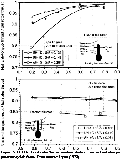
Tail rotors may be either of the pusher or tractor variety and can be located either on the left – or right-hand side of a vertical fin. All designs suffer from interference effects between the rotor and the fin, these effects being a function of the tail rotor size or disk area, A, fin area, S, and spacing of the rotor plane from the fin. The effects are summarized by Lynn (1970), and representative measurements are reproduced in Fig. 6.33 in terms of net anti-torque producing side-force versus fin/rotor separation distance. The results are shown for various ratios of fin area to tail rotor disk area, S/A. In the pusher style the wake of the tail rotor is convected away from the vertical tail. This means that the vertical fin only

Fin separation distance / rotor radius

Подпись: Figure 6.33 Effects of rotor/fin separation distance on net anti-torque producing side force. Data source: Lynn (1970).

distorts the inflow into the tail rotor, the consequences of which are a nonuniform inflow and higher induced power requirement. It can also be a source of 2/rev (2Nb) vibratory airloads. In contrast, the tractor design has the vertical fin located inside the high-energy region from the tail rotor wake. While this “blockage” effect tends to increase the tail rotor thrust, there is also a significant force applied to the vertical tail that is in the opposite direction to the anti-torque thrust requirement. It is found, however, that the net effect is a decrease in thrust compared to what would be obtained if the rotor was operating in isolation. In both cases, the interference effects become greater with larger fins and/or smaller rotors. A majority of modem helicopters use a pusher tail rotor design because this configuration tends to have a higher overall anti-torque producing efficiency.

. Precessional Stall Issues

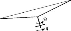
A problem that has occurred on tail rotors that can limit its thrust is a phenomenon known as precessional stall – see Lynn (1970). The tail rotor has no cyclic pitch and so it is free to flap in response to the changing aerodynamic forces. The tail rotor is subjected to higher effective angular rates than the main rotor as a result of yawing maneuvers, these rates being relatively large during turns about a point in hovering flight (so-called “spot – turns”). As described in Chapter 4, the rotor basically acts like a gyroscope so that when its shaft axis is suddenly tilted as the helicopter yaws the tail rotor initially maintains its orientation in inertial space – see Fig. 6.31. However, the tilting of the rotor shaft produces a change in blade pitch with respect to the original orientation of the tip-path-plane (TPP) and so a cyclic variation in blade lift is produced. This lift acts to create blade flapping and so begin to precess the rotor. The rotor plane, therefore, will align itself so that it once again becomes perpendicular to the rotor shaft. This realignment occurs rather quickly, certainly within one rotor revolution.

If the tail rotor shaft undergoes continuous angular displacements such as would be produced by the helicopter undergoing a yawing motion, the rotor disk will continuously try to realign itself. Because the realignment does not happen immediately, eventually the time rate of change of shaft displacement can become sufficiently high that the rotor TPP lags behind the shaft plane by a finite angle – see Fig. 6.32. The additional flapping moment on the blades resulting from gyroscopic effects on a rotor with pitch rate q and roll rate p is

. Precessional Stall Issues . Precessional Stall Issues

Mg = —2Ib&q sin ф — 2h^p cos ф, (6.38)

(a) Where TPP actually is (b) Where TPP should be

Figure 6.32 A lag in tilt of the TPP is produced when the shaft is tilted at a finite rate.

which is derived in Gessow & Crim (1955) and Brown & Schmidt (1963). Solving the equation of motion for a flapping blade (Eq. 4.5) with these additional terms gives the flapping response of the rotor. For a combination of pitch rate q and roll rate p about the rotor у (lateral) and x (longitudinal) axes respectively, the lag in the blade flapping displacements (relative to where the TPP would be under steady conditions) are

which is for a rotor with no hinge offset, where у is the Lock number (see page 179) and д is the advance ratio of the rotor. It can be assumed for the tail rotor that a yaw rate Ф == q. This means that for a nose right yaw rate the tail rotor experiences an effective nose up pitch rate, causing a longitudinal lag in the blade flapping response combined with some smaller lateral flapping response.

The upshot is that when the angular rates (the yaw rate in this case) become sufficiently large, the blades will experience substantial changes in angles of attack that would be necessary to produce the aerodynamic forces to precess the tail rotor. For high enough rates, therefore, the flapping tail rotor blades will operate at such large angles of attack that they will approach stalled conditions. Because stall occurs as the tail rotor attempts to create aerodynamic forces to cause blade flapping and precess the orientation of the rotor plane, this phenomenon is called precessional stall. Precessional stall, therefore, can limit the anti-torque and directional (yaw) control of the tail rotor, and so can set a limit to overall helicopter performance. Lynn (1970) describe how this phenomenon may reduce attainable yaw rates. The situation is, of course, exacerbated when the helicopter is operating at high weights and/or high density altitudes whenever the tail rotor is operating under demanding thrust requirements and the blades are generating high lift coefficients.

In forward flight the tail rotor blades are already undergoing some flapping motion as a result of the dissymmetry in lift between the advancing and retreating sides of the disk. Therefore, by means of Eq. 6.39, it is apparent that relatively smaller angular yaw rates could produce precessional stall onset. Tail rotors typically have lower Lock numbers than the main rotor and, according to Eq. 6.39, the precessional effects will be relatively stronger, all other factors being equal. The onset of precessional stall can be reduced by using blades with increased Lock number (a byproduct of increased blade weight and flapping inertia) or by using rotor airfoils with larger C)max capability. Extra blade weight, however, is certainly not desirable and higher C/max is difficult to obtain without increasing torsional blade moments and control forces (see Section 7.7).

Thrust Requirements

The primary purpose of the tail rotor is to provide a sideward force on the airframe in a direction and of sufficient magnitude to counter the main rotor torque reaction. The tail rotor also provides the pilot with directional (yaw) control. Roughly, the tail rotor consumes up to about 10% of the total power for the helicopter, although allowances of up to 20% may

Подпись:Подпись:Подпись:

Thrust Requirements

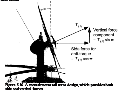
be made for design purposes to ensure sufficient maneuvering and transient capabilities. This is power that is completely lost, because unless the tail rotor is canted, as on the UH-60 Blackhawk (Fig. 6.30), it provides no useful lifting force. The purpose of the canted tail design is to widen the allowable center of gravity of the helicopter. This design, however, introdi

a flight control system.

The direction of the anti-torque force depends on the direction of rotation of the main rotor. For a rotor turning in the conventional direction (counterclockwise direction when viewed from above), the tail rotor thrust is to the right (starboard). The magnitude of this thrust, as well as its power consumption, depends on the reaction torque from the main rotor, Qmr, and the location of the tail rotor from the center of gravity (i. e., the moment arm Imr)- In addition, there are inertial effects that the tail rotor must overcome during yawing maneuvers. In this case, the tail rotor thrust can be found from

Qmr + hz^ — TtrItr (6.37)

where Ф is the yaw acceleration and Izz is the mass moment of inertia of the helicopter about the yaw axis.

The tail rotor thrust is controlled by the pilot’s feet by pushing on a set of floor mounted pedals. For example, for a rotor turning in the conventional direction pushing on the left pedal increases tail rotor thrust (positive to starboard) and the helicopter will yaw nose left about its center of gravity. The tail rotor must also provide the specified yaw acceleration in the maximum specified crosswind conditions, taking into consideration possible losses in efficiency because of aerodynamic interference effects between the tail rotor and the vertical fin – see Section 6.9. Furthermore, when the main rotor thrust or power is increased, for example, to climb, the reaction torque, Qmr, on the fuselage is increased. This means that the tail rotor thrust must also increase to balance this torque reaction. Therefore, when the pilot increases the collective pitch to climb, foot pressure must be applied to the appropriate pedal to keep the nose pointed straight in the desired direction of flight.