Category Principles of Helicopter Aerodynamics Second Edition

Aerodynamic Design of Helicopters

We built the first helicopter by what we hoped was intelligent guess. It was time of crystal ball.

Igor Alexis Sikorsky (1957)

6.1 Introduction

There are many fundamental issues, some of them conflicting, in the aerodynamic design of the modern helicopter. Helicopter designers are concerned with overall aircraft performance, rotor and airframe loads, vibration levels, external and internal noise, sta­bility and control characteristics, and aircraft handling qualities. Specific emphasis in this chapter is placed on the general elements and features contributing to the aerodynamic design of helicopter main rotors and related components. However, many of the issues and arguments are applicable to other types of rotorcraft as well. The first part of this chapter outlines the basic sizing and overall optimization methodology of helicopter main rotors. This ultimately leads to the further consideration of rotor airfoil sections and the need for good airfoil designs, the trade-offs in blade planform design, and the role of tip shape in the efficient design of the modem rotor. While helicopter design is often synonymous with rotor aerodynamics, the aerodynamics of the fuselage has received considerable attention in recent years and now constitutes an important part in the overall design process of the modem helicopter. The general issues associated with the selection of anti-torque produc­ing devices such as conventional tail rotors and other concepts are also discussed. Finally, some significant aerodynamic design issues associated with human powered helicopters and micro air vehicles are outlined.

Chapter Review

This chapter has addressed some elementary analyses and predicted results that define the overall performance characteristics of the helicopter in hover, climb, forward flight, and during certain types of maneuvers. It has been shown that these performance characteristics can be derived, in part, by using relatively parsimonious mathematical models for the rotor aerodynamics that have their origin in the momentum and blade element theories given in previous chapters. Good estimates of rotor profile power can be made on the basis of blade element theory, perhaps allowing for radial, yawed, and reversed flow effects and also for compressibility losses at high speeds. Airframe drag has been discussed, and the modeling of these effects has been introduced through the ideas of an equivalent wetted or flat-plate parasitic area. Airframe drag increases rapidly on a helicopter in higher – speed forward flight, eventually becoming one limiting factor in defining its maximum speed capability. The resulting models give good approximations to the rotor power required and performance of the helicopter over the substantial part of the operational flight envelope. The results can be used to estimate performance as functions of helicopter weight and operational factors such as its density altitude. Performance issues such as the speed to fly for maximum range or endurance have been discussed, and it has been shown how these results follow directly from a knowledge of the power required curves.

However, the performance of modem helicopters is mostly limited by other aerodynamic factors, such as blade stall and compressibility effects on the rotor. While compressibility effects show up as progressive increases in power required in high-speed forward flight, the onset of blade stall is more critical because it is a source of high unsteady blade loads and increases in vibration. Both compressibility and stall effects are difficult to model without resorting to more thorough types of analyses that model the aerodynamics at a more fundamental level, such as using the blade element approach. These phenomena and methods for their approximation will be considered in the following chapters.

Helicopter performance when operating near the ground or in a wind tunnel has also been discussed. The complexity of the recirculating flow near the ground is such that this particular aerodynamic problem is not amenable to easy solution and the problem must be modeled semi-empirically. An introduction to the maneuvering flight capability of helicopters has been given based on simple kinematics for steady maneuvers and using an energy approach for the transient case. It is apparent that much can be demanded from the modem military helicopter, which must be able to maneuver effectively. Clearly the most important aspect of maneuverability is the ability of the helicopter to produce extra rotor thrust over and above that required for flight at the original equilibrium flight condition. The extra rotor thrust, however, may be limited because of installed power limitations, transmission torque limits, blade stall, rotor rpm limits, or structural loading limits. Finally, potential performance degradation effects from the effects of airframe and rotor icing has been reviewed.

Factors Influencing Performance Degradation

The performance of a helicopter can be degraded under different circumstances. The accumulation of dirt and dead insects on the leading edges of the blades can degrade both main and tail rotor performance, although these effects are relatively mild. Estimates of such effects on rotor performance can be obtained by increasing the value of in
accordance with measured effects of roughness on 2-D airfoil sections (see Section 7.9.1). The operation of the helicopter in dusty or desert environments can lead to blade erosion, and this can have much more deleterious effects on rotor performance. А С^0 allowance of up to 50% can be used to represent such effects in rotor performance estimation. Aerody­namic degradation of the rotor performance from battle damage can be an issue for military helicopters, but such effects are much more difficult to predict (see Section 7.14). Never­theless, an assessment of degraded effects on rotor performance is essential for assessing operational risks to military helicopters in a combat environment.

Icing is a particularly significant factor that can degrade rotor performance. For good utility, helicopters must be designed to operate in an all-weather environment, of which flight in extremely cold conditions are not uncommon. However, icing can occur under other atmospheric conditions, and there is a risk whenever visible moisture is present in the air. Under certain conditions, ice accumulation on the rotor and airframe may occur. Icing characteristics of helicopters are similar in some respects to airplanes, and ice may accumulate on windshields, engine inlets, the leading edges of the empennage, antennas, Pitot probes, and so on. Icing can result in a serious performance degradation and may also affect flight control capability. The field as applied to helicopters is comprehensively reviewed by Flemming (2002).

Ice accumulation may increase the parasitic drag of the airframe. Engine inlet icing may reduce engine power and in extreme cases can cause engine surge-stall. However, airframe, engine inlet, and windshield icing can be dealt with effectively by electrical deicing. Em­pennage icing and the associated aerodynamic degradation is usually less important for helicopters than for airplanes because icing may only affect trim, and on most helicopters the rotor itself has ample flight control capability to compensate for this. Icing on the rotor, however, can have serious consequences, with a significant degradation in aerodynamic capability – see Flemming et al. (1987). Because the type and accumulation of ice normally varies in a 3-D manner along the blade span, and may be different from blade to blade, icing can be accompanied by significant rotor vibrations. Modem helicopters may be ca­pable of flight into icing conditions with suitable deicing protection, but most helicopters are not certified for flight onto known icing conditions because of the amount of flight certification tests and high costs incurred by the manufacturer. Icing protection on the rotor is provided by electrically heated deicing mats that are molded into the composite blades during manufacture [see Rauch & Quillien (2003)], but Coffman (1987) discusses other concepts.

Steady 2-D airfoil testing in special icing wind tunnels has allowed measurements of ice accumulation at the leading edge of rotor airfoils, which have shown substantial degradation on aerodynamic performance – see Flemming & Lednicer (1985). Unsteady tests on airfoils, which are designed to more accurately simulate the time-varying flow environment at the rotor, have suggested different ice shapes may accumulate, with smoother profiles because of the continuously varying AoA. Tests with subscale rotors in special icing tunnels has been conducted to more accurately assess the susceptibility of helicopters and their rotor systems to icing – see Korkan et al. (1984) and Flemming & Saccullo (1991). These icing shapes can be used to cast molds to modify the blades of other model rotors, which are then tested in dry-air tunnels in an attempt to measure the effects on rotor performance. Scaling issues (such as Reynolds number effects and heat transfer) that are associated with ice accumulation on model rotors are, however, not well understood. Therefore, confidence levels in extrapolating wind tunnel results to estimate the impact of icing on the full-size rotors is not yet acceptable. Various mathematical models have also been developed to assess the effects of icing on rotor performance both empirically [see Korkan et al. (1984)] and by using modem CFD approaches [see Narramore et al. (2002)]. However, validation is lacking because of the limited amount of existing flight test data, and so predictive confidence levels with CFD alone remain lower than required to satisfy the certification authorities. Actual in-flight icing tests are often augmented by artificial tests to cover the full flight envelope of the helicopter – see Ramage (2004). Computational methods continue to be developed, however, to enable better predictions of the aerodynamic characteristics with ice accreted on the entire rotorcraft with the ultimate goal of reducing significantly the amount of required certification flight testing [see Narramore et al. (2003)].

Transient Maneuvers

The analysis of the transient (nonsteady) maneuver of a helicopter can be ap­proached using energy methods – see Schillings et al. (1990), Lappos (1984), and Ebert & Lappos (1985). The instantaneous energy state of the helicopter, E, can be written as a sum of its potential energy, translational kinetic energy and the rotational kinetic energy stored in the rotor, that is,

1/W і 1 9

E = wh + – l-jvl + – IRn (5.109)

Transient Maneuvers

Подпись: dE dh (W — =W— + — dt dt  g Transient Maneuvers Подпись: (5.110)

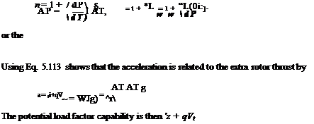
where W is the weight of the aircraft, h is its altitude relative to a datum (normally the ground), Vqo is true airspeed, IR is the rotor inertia, and Q is the rotational speed of the ro­tor. The time rate of transfer of energy between these three different energy states of the helicopter is equivalent to the power required to change the energy level. This transfer of excess power provides a measure of maneuver capability and the rate of transfer of power is a measure of its potential agility (i. e., the quickness of the maneuver). By differentiating Eq. 5.109 with respect to time this gives

The net excess power available can be written as a contribution from the engine(s) and from the rate of change of energy level associated with changes in the flight condition, that is, the net excess power available is

AP — APengine + A Penergy level) (5.111)

where A P can be viewed as the net excess power available over and above that required for equilibrium flight at any one flight condition (i. e., at any given altitude, airspeed, rotor rpm and maneuver state). For example, any excess power available can be used to increase potential energy (gain more altitude), to increase kinetic energy (gain more airspeed), to increase the rotor energy (increase rotor rpm) or otherwise change the flight condition. The signs and magnitude of the various energy rates define the nature of the changes that are possible to the flight condition of the helicopter. For most normal flight conditions the rotor rpm is automatically governed to allow only small variations, but an overspeed (but not much of an underspeed) of the rotor can be allowed under some conditions.

The energy to produce extra rotor thrust to perform an accelerated maneuver comes from either excess shaft power available or from the conversion of one energy state to another. Rotor overspeeds can also be used for this purpose (T cx f22), but rarely is this done in practice because of the risk of overstressing the rotor. Rotor overspeeds, however, are often used during the final transient stages of an emergency autorotative maneuver, where the pilot will flare the helicopter to a steep nose-high attitude to gain excess rotor rpm to aid in a safe touchdown – see page 248.

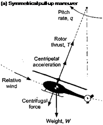
For a conventional helicopter the rotor thrust T can be estimated from the product of the gross weight of the aircraft W and the rotor load factor n. Consider a helicopter undergoing a simple pull-up maneuver, as shown in Fig. 5.40(a). The normal acceleration, a, is

a = (n – l)g =z + qVOQ. (5.112)

The potential load factor also depends partly on the ability to produce a normal (vertical) acceleration z through the application of blade pitch. The helicopter must have, therefore, an excess power available at the rotor shaft over and above that required for level, unaccelerated flight at the same conditions (i. e., at the same airspeed, weight, and density altitude). Notice that the potential load factor also depends on the energy level through the flight velocity and the ability to actually produce a pitch rate q through the application of flight control inputs.

The excess power available A P over and above that power required P at a given airspeed Too is available to produce extra rotor thrust AT and, therefore, to produce an acceleration. In horizontal flight (or conditions that may be nearly so) the equation of motion is

The load factor on the helicopter is then

(5.114)

The ability to produce this load factor depends on the stall margin of the rotor, which in this case can be defined in terms of the value of Cj I о that will produce stall relative to the lg level flight value, that is,

Подпись: CT (5.115)

IfATsm > 1 then the rotor stall boundary will be exceeded before the power limit is reached. Therefore, an excess power available is no guarantee of maneuver capability, and both power and rotor stall margins must be addressed.

The load factors possible with a conventional helicopter are shown in Fig. 5.41, where a helicopter was flown in various transient maneuvers such as decelerating pull-ups and turns at different airspeeds in an attempt to define its transient maneuver envelope – see Lappos & Padfield (1994). The demonstrated (flight-tested) load factors are limited at low airspeeds by the low translational kinetic energy and by the relatively low excess power margin of the conventional helicopter. This type of comparison can, for now, be considered only qualitative in nature but it serves to illustrate how the shape of the measured maneuver envelope at low flight speeds mimics the excess engine power available (power margin) curve – see discussion in Section 5.5.4. It is reasonable to assume that this behavior is typical of any conventional helicopter (i. e., one without benefits of lift or thrust compounding).
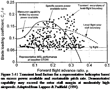
Подпись: Figure 5.41 Transient load factors for a representative helicopter based on excess power available and sustainable pitch rate. Demonstrated capability may exceed the rotor stall margin at moderately high airspeeds. Adapted from Lappos & Padfield (1994).

At intermediate forward flight speeds the transient maneuver capability is less dependent on the excess engine power available because the power margin is greater as rotor induced losses are lower, and also because the higher translational kinetic energy of the helicopter

Transient Maneuvers

allows for a transfer of energy (see Eq. 5.110). Flight test results indicate that in some cases these transient load factors may be of the order of 3g and are likely to well-exceed the normal static stall boundary of the rotor and approach its structural limits. Some part of these overshoots in the static stall envelope can be attributed to the delay in the onset of stall that is associated with the favorable effects of pitch rate on stall – a phenomenon recognized by Brown & Schmidt (1963) and discussed in detail in Chapter 9. There are also gyroscopic effects on the rotor during maneuvers, which affects the blade flapping response (see Section 6.9.3). The corresponding changes in blade section AoA can add or subtract from the stall margins depending on the nature of the maneuver (rolls to the left or right,

The potential maneuver capability from the excess engine power available can be es­timated with reference to the engine power required versus power available curves. The excess rotor power available Д Peng can be related to the potential of increasing rotor thrust, AT. In low-speed flight (i. e., near to hovering flight), it is sufficient to assume the hover result relating rotor power required to rotor thrust using the momentum theory, that is,

/ 1 7*3/2

P =———- —=, (5.116)

FM) V2^A ’

where A is the rotor disk area, FM is the rotor figure of merit, and p is the air density at the actual operational flight conditions. Differentiating the power equation with respect to thrust gives

Подпись: dP dT (5.117)

Transient Maneuvers Transient Maneuvers

Linearizing the problem by assuming the excess thrust and engine power are a fraction of those required at the level, unaccelerated flight condition means the excess power can be written as

Using the result from Eq. 5.117, and assuming that the increase in thrust is relatively small compared to the thrust required for level, unaccelerated flight at that gross weight and

density altitude gives the potential load factor as

Подпись: nTransient Maneuvers(5.122)

where it is assumed that all of the excess engine power available can, in fact, be used to generate an extra rotor thrust (i. e., the rotor is not stall limited before being power limited). Therefore, Eq. 5.122 confirms the hypothesis made earlier that the ability to produce a maneuver load factor on the aircraft depends on the specific excess power available. This particular result is valid at low airspeeds where the translational kinetic energy is low and where the shape of the excess power available curve closely mimics the actual maneuver capability of the helicopter.

This problem can also be examined by assuming that the power required by the rotor is approximated by the forward flight result

p = T^7T + po + Pp^ (5-123)

IpAVoo

Подпись: P Transient Maneuvers Подпись: (5.124)

where P0 is the profile power required and Pp is the parasitic power. The first term in Eq. 5.124 is the induced power required as given by Glauert’s approximation (Eq. 2.114). The profile and parasitic terms are primarily a function of flight speed V^. The profile term is nominally constant in low-speed flight, and the parasitic term increases only slowly when in low-speed forward speed. Therefore

By differentiation of Eq. 5.124, the approximate change in power required with respect to a change in rotor thrust can be written as

Подпись: (5.125)dP _ kT dT pAVoo

Подпись: n Transient Maneuvers Подпись: (5.126)
Transient Maneuvers

As before, linearizing the problem by assuming the excess power (and thrust) is a fraction of the power available means the excess power can be written in terms of the excess thrust. Using the result in Eq. 5.125 by assuming that the change in rotor thrust is a fraction of the thrust required at that aircraft weight, gives the potential load factor as

These results help quantify the effects of excess engine power available on the potential maneuver capability of the helicopter, which approximately mimics the curve of excess power available relative to level flight. However, it is clear that the maneuver capability depends on many interrelated parameters, including the translational kinetic energy of the helicopter, the kinematics of its flight trajectory, and the stall margins of the rotor.

Steady Maneuvers

Подпись: T = Подпись: (5.104)
Steady Maneuvers Steady Maneuvers

For steady (nontransient) maneuvers, the forces acting on the helicopter can be assumed to act in equilibrium. A classic problem is a level banked turn, which is considered by Saunders (1975) and Prouty (1986). By assuming the helicopter to act as a point mass, the centripetal acceleration required to perform a turn with a flight path of radius Rtum will be V^//?tum, where Too is the true airspeed. With reference to Fig. 5.40(a), the rotor thrust required must overcome both weight W and centrifugal force Fqf giving

Steady Maneuvers Подпись: 1 + Подпись: V2 2 r OO I gRtum ) Подпись: (5.105)

This result, of course, assumes that the tail rotor makes a negligible contribution to the problem. The load factor on the rotor is, therefore,

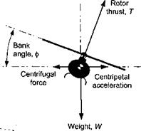
where n is the rotor load factor (n = 1 in level, unaccelerated flight) and g is acceleration under gravity. The bank angle required [refer to Fig. 5.40(b)] will be

ф = cos-1 (1/n) (5.106)

and so for equilibrium the rotor thrust, T, is

T = W/cos(p. (5.107)

These equations allow the rotor thrust to be determined, albeit approximately, for any bank angle and, therefore, for any turning radius of the flight path. Notice that the bank angle required to perform a given radius of turn will also be a function of the speed of the helicopter along its flight path, which is a key factor in determining the load factor for a given radius of turn.

Подпись: (a) Symmetrical pull-up maneuver
Steady Maneuvers

(b) Steady turn

Figure 5.40 Forces acting on a helicopter in (a) a symmetrical pull-up maneuver and, (b) a coordinated tum.

к(Ст/cos ф)2 aC,

2^X2 + /X2- 8

Подпись: r„ = Подпись: П Steady Maneuvers

The power required in turning flight with bank angle ф can be determined using the performance model based on momentum theory, as described in Section 5.4. In coefficient form, the total power can now be written as

where CpTR is the contribution from the tail rotor.[21] Notice that it is only the induced part of the power (the thrust dependent term) that is affected by the bank angle, ф, assuming that the tum is coordinated and there is no slip (yaw) angle. For modest bank angles, say up to ф = 30°, there are only mild effects on power requirements. However, for steep bank angles the power required may exceed that available and the maneuver capability could be power limited. This is particularly apparent at high density altitudes, where maneuver performance will almost certainly be limited because of either reduced excess power available or by reaching rotor stall limits. Roll rate (or pitch rate for that matter) has only a secondary and transient effect on rotor power required because rate affects primarily the distribution of thrust over the rotor disk and not its magnitude.

Performance in Maneuvering Flight

Maneuver requirements will set the ultimate flight capability for a helicopter. Therefore, the prediction of the rotor airloads under maneuvering conditions forms an essential part of the overall design process. Yet this is a difficult task made even more com­plicated by the generally nonlinear aerodynamics of the rotor, and the complex kinematics of the rotor and the helicopter under most types of maneuvering flight conditions – see Padfield (1996) for an overview of the issues. Limiting aerodynamic factors in maneuvers may include stall and the effects of the wake, which can induce vibratory airloads from blade vortex interactions. The proper prediction of helicopter maneuvering performance is an illusive goal that will challenge helicopter analysts for years to come.

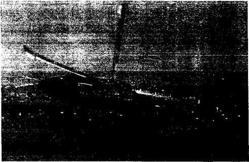
Maneuver issues are of particular importance for military helicopters – see Lappos (1984). A modem military helicopter may be required to perform maneuvers consisting of high load factor turns and pull-ups, steep turns and rollovers (see Fig. 5.39), arrested high rates of descent in combat landing zones, and quick pop-up-pop-down maneuvers for battlefield observation – see Thomson & Bradley (1990). Rotor stall issues are often a key consideration under these conditions because of the extra thrust demanded from the rotor, and sufficient stall margins must be incorporated into the rotor design. Both military and civil requirements will dictate the rotor capabilities that must be demonstrated without the rotor stalling. Maneuvers cause the rotor flapping response to lag with respect to the maneuver rates of the helicopter, which can also affect blade angles of attack and stall margins – see discussion in Section 6.9.3. Consideration of rotor noise levels and retention of good helicopter handling qualities have also become important factors in the design of helicopters with good maneuver capabilities.

The ability of a helicopter to maneuver (such as a pull-up or sustained horizontal turn) depends, in part, on the excess thrust possible from the rotor and the excess power available

Performance in Maneuvering Flight

Figure 5.39 A Lynx helicopter executing a steep banked turn maneuver. (Photo courtesy of Agusta-Westland via F. John Perry.)

over and above that required for level, unaecelerated flight. The load factor on the rotor, n, can be defined as the net thrust of the rotor divided by the gross weight of the helicopter, that is, n = T/W. The ability to produce a given load factor on the rotor depends on: 1. The ability of the helicopter to actually sequence a maneuver with the use of normal flight controls; 2. The effective management of potential, translational kinetic, and rotor rotational kinetic energy by the pilot through the use of flight controls; 3. The excess energy or power available at that airspeed (i. e., having excess translational kinetic energy or an engine with sufficient power margin); 4. The ability of the rotor to actually use that excess power and produce a load factor without stalling (i. e., the rotor must be designed to have sufficient stall margin); and 5. The structural strength and aeroeiastic margins of the rotor at the higher accelerations and load factors associated with maneuvering flight. Therefore, the ability of the rotor to produce and sustain a load factor can be viewed as one measure of the ability of the helicopter to maneuver. The problem of defining a load factor, however, can be a relatively complicated one for a helicopter when all the kinematic relationships of AoA, sideslip and bank angle are taken into account; the load factor measured by an accelerometer on the aircraft is not necessarily the same as the load factor being produced by the rotor – see Chen & Jeske (1981).

Forward Flight Near the Ground

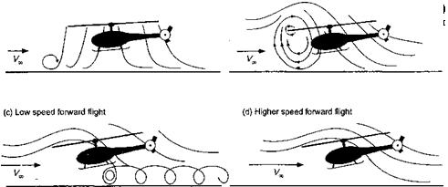
The effects of the ground on rotor performance in forward flight are also significant, but here the flow state near the rotor tends to be even more complicated. The typical behavior is shown in Fig. 5.37, which is adapted from the work of Curtiss et al. (1984, 1987). At low forward speeds, a region of flow recirculation is formed upstream of the rotor near the ground. This phenomena has negligible effects on performance but may throw loose surface material up into the air that may be reingested by the rotor. As forward speed increases, this recirculation develops into a small vortical flow region between the
ground and around the leading edge of the rotor. This vortex has been documented both in wind-tunnel experiments and helicopter operations in the field. For helicopters operating in a dusty or snowy environment the flow recirculation upstream of the rotor becomes particularly evident. This recirculation increases the inflow through the forward part of the rotor disk, and, as a consequence, the induced power requirements will increase above that

Подпись: плхі;аг со'

Подпись: 11ПІ Uiiuc. uui

Forward Flight Near the Ground

required for hover IGE. The pilot, therefore, experiences a form of “p collective pitch is increased to maintain altitude as the aircraft transitions into forward flight. Above a critical advance ratio, which depends on aircraft weight (rotor thrust) and proximity to the ground, a well-defined horseshoe vortex (ground vortex) is formed under the leading edge of the rotor near the ground. With further increases in airspeed, this phenomenon disappears as the rotor wake is skewed back by the oncoming flow. Ground effect is usually considered negligible for Vqo > 2Vh or for advance ratios greater than about 0.10. See also Section 14.10.6 for a further discussion of ground effect on rotor aerodynamics.

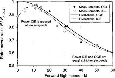
A representative set of results of rotor power in forward flight for operations in both IGE and OGE is shown in Fig. 5.38, which is reproduced from the wind-tunnel measurements of Sheridan & Weisner (1977). The advantages of ground effect are apparent for hover and very low airspeeds, where the effects indicate considerable power reductions compared to flight OGE. Note that for operation IGE the power increases rapidly as the helicopter transitions from the hover state. This is because of the formation and influence of flow recirculation at the leading edge of the rotor disk, as previously alluded to, which causes the rotor to experience a higher induced inflow than for hovering flight IGE. This increases slightly the power requirements, as previously mentioned. Similar types of results showing the same effects have been obtained by Cheeseman & Bennett (1955) on the basis of flight tests.

Similar rotor-ground plane interference effects are noted in wind tunnel tests on rotors, where the effects of the tunnel floor (as well as the ceiling and side walls, if present) can alter the induced flow through the rotor. Ganzer & Rae (1960) and Lehman & Besold (1971) have studied the effects experimentally. If the objective is to simulate free-air conditions with the rotor, then the presence of the walls on rotor performance cannot be easily discounted,

Forward Flight Near the Ground

Figure 5.38 Measurements and predictions of rotor power versus forward speed when operating near the ground. Data source: Sheridan & Weisner (1977).

especially at low airspeeds. For tunnel dimensions that are at least twice the diameter of the rotor, the effects of the wind tunnel walls are small for advance ratios greater than 0.1. Generally, it must always be assumed that the effects of the tunnel walls will lead to some flow recirculation at lower advance ratios (say, д < 0.1) making reliable free-air measurements of rotor performance difficult or impossible, even if suitable corrections could be derived – see also Philippe (1990). Measurement of the wall pressure signatures allows the investigator to monitor interference effects and help define the lowest allowable wind speed for a given rotor thrust and/or advance ratio that can be tested without the results being contaminated by wall interference effects. Deviations of the wall pressures from their static values will be a sensitive indicator of such interference effects, although correcting the rotor measurements is a more difficult problem. It would seem that minimizing the interference effects in the first place is the best strategy for testing helicopter rotors, which suggests the use of large wind tunnels or wind tunnels with open working sections.

Other studies of the flows associated with rotors operating IGE have used both vortex methods and grid-based computational fluid dynamic (CFD) methods. A free-vortex wake model is described by Du Walt (1966) who assumed an axisy mmetric, periodic wake. Ground effect was simulated by modeling the problem as a mirror image wake below the ground plane, and studies were conducted for varying rotor heights and advance ratios. Similar types of models have been developed by Saberi & Maisel (1987), Quackenbush & Wachspress (1989), Graber et al. (1990), Itoga et al. (1999), and Griffiths & Leishman (2002). While predictions of wake behavior in hover and in forward flight has been demonstrated, relatively limited success has been achieved in correctly predicting rotor performance IGE when compared to experimental results. This reflects the inherent complexity and strongly viscous nature of the rotor IGE flow problem. The use of most forms of CFD methods do not yet have seen to have reached the maturity for predicting rotor performance IGE, but approaches such as that discussed by Moulton et al. (2004) at least seem promising for predicting the effects of the rotor downwash at regions below the rotor, which is important for several operational reasons. The best current quantitative levels of predictive success for ground effect problems using CFD have been achieved using vorticity transport models – see Section 14.3.

Ground Effect

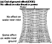
Helicopter performance is affected by the presence of the ground or any other boundary that may alter or constrain the flow into the rotor or constrain the development of the rotor wake. The effect has long been recognized, but the aerodynamics of the rotor under these conditions are still not fully understood. “Ground effect” is of concern both in actual flight operations as well as in the wind tunnel or hover tower testing of rotors.

(b) In ground effect (IGE)

Подпись:Подпись: Figure 5.35 The behavior of the wake from a hovering rotor: (a) Out of ground effect (OGE). (b) In ground effect (IGE). (Flow visualization photos courtesy of Sikorsky Aircraft.)
Large effect on rotor thrust and/or power

Rotor height n

off the ground

Ground Effect

5.8.1 Hovering Flight Near the Ground

Consider a rotor hovering in close proximity to the ground, as shown in Fig. 5.35. Because the ground must be a streamline to the flow, the rotor slipstream tends to rapidly expand as it approaches the surface. This alters the slipstream velocity, the induced velocity in the plane of the rotor, and, therefore, the rotor thrust and power. Similar effects are obtained both in hover and forward flight, but the effects are strongest in the hovering state. Other visualization of the flow of hovering rotors operating in ground effect are shown by Taylor (1950) and Light & Norman (1989). Systematic studies of rotors operating in ground effect were first conducted by Knight & Hefner (1941).

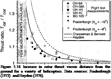
When the hovering rotor is operating in ground effect, the rotor thrust is found to be increased for a given power. A representative plot of the thrust ratio in hover versus height from the ground is shown in Fig. 5.36. This plot has been derived from several experiments with rotors operating at different blade loadings, as discussed by Zbrozek (1947) and others, including Betz (1937), Knight & Hefner (1941), Cheeseman & Bennett (1955), Fradenburgh (1960,1972), Stepniewski & Keys (1984), and Prouty (1985). Hayden (1976) gives a com­prehensive summary of flight test measurements of ground effect using the standardized technique of Lewis (1972). The results suggest significant effects on hovering performance for heights less than one rotor diameter. The results are also dependent somewhat on blade loading (or mean lift coefficient), blade aspect ratio, and blade twist. Yet, within the bounds dictated by most helicopters a universal behavior seems a good approximation for engi­neering estimates of the phenomenon. Besides the effects on actual helicopter performance, these results provide useful guidelines for laboratory testing of rotors in hovering flight,

Подпись: 1.4

0.5 1 1.5 2 2.5 3

Подпись: Figure 5.36 Increase in rotor thrust versus distance from the ground for a variety of <a href=helicopters. Data sources: Fradenburgh (1972) and Hayden (1976). ” width=”362″ height=”258″/>

Height above ground, z / R

where a minimum distance of at least 2R from the ground is required to ensure performance measurements that are free of interference effects.

The problem of ground effect can also be viewed as a reduction in power for a given thrust. Most of the power reduction is induced in nature, but there is also some small re­duction in profile power because the blade angles are operating at a somewhat lower AoA to produce the same thrust. Because of ground effect there is an important operational advantage to be gained, namely that the lower power required will allow the helicopter to hover in ground effect (IGE) at a higher gross weight or density altitude than would be possible out of ground effect (OGE). The extra thrust or reduction in power require­ments that is felt near the ground will also “cushion” the descent of the helicopter when landing.

Ground Effect Подпись: (5.96)

Ground effect in hovering flight has been examined analytically, albeit approximately, by means of the method of images. Cheeseman & Bennett (1955) replaced the rotor by a simple source with an image source to simulate ground effect and obtained some analytic relationships for the effects of the ground. Knight & Hefner (1941) and Rossow (1985) have used a vortex cylinder model. Based on Cheeseman & Bennett’s analysis, ground effect on the rotor thrust can be expressed by the equation

where z is the height off the ground and X,- is the induced velocity at the rotor. This equation has a validity of z/R > 0.5. Incorporating the effect of blade loading they obtained

Подпись: 4 Cr 1 + 0хЛі)2 (5.97)

although Ст /о – has a secondary effect. For hovering flight and neglecting any blade-loading effects this latter result simply becomes

=——— l—— -. (5.98)

[°ojp=const 1 — (Я/4 z)

Figure 5.36 shows that this equation gives good agreement with the experimental mea­surements. Because ground effect can be expressed in terms of the increase in thrust at a constant power, then Хюе Ctige — Xoge Ctoge or

Подпись: Ґ5X/ge _ Tqge

xOGE TlGE

Подпись: P OGE J T=COnSt Подпись: (5.100)
Подпись: Cr

Alternatively, the influence of ground effect in hover can be viewed as a reduction in the rotor induced velocity (at a constant thrust and height above the ground) by a factor kc such that

" Power required IGE "

Г Pige

Power required OGE

T =const

L POGE.

P IGE

This means that up to a 25% reduction in the induced velocity and the induced power is possible with the Cheeseman & Bennett model.

Подпись: PIGE PoGE. Ground Effect

Using a relatively simple model, Betz (1937) has suggested the effect on the rotor power at a constant thrust to be modeled by the equation

Hayden (1976) has used flight test measurements to find the influence of the ground in hover. The profile part of the total power was assumed to be isolated from the induced effect such that only the induced effect is influenced by the ground, that is,

Подпись:P = Pq + кс{Рі)юЕ,

Подпись: kG Подпись: 1 A + B(2R/z)2 Подпись: (5.103)

where kc is derived from a curve fit to the experimental data using

with A — 0.9926 and В = 0.0379. As shown by Fig. 5.36, when viewed in terms of an increase in thrust for a given power, Hayden’s result is found to slightly overpredict the rotor thrust. In all cases it is apparent that the effects of the ground on the rotor performance become negligible for rotors hovering greater than three rotor radii above the ground.

Implications of VRS on Flight Boundary

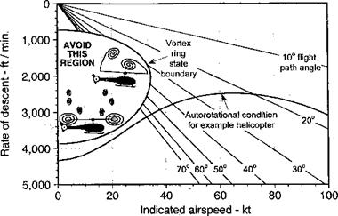
The adverse conditions associated with VRS mostly occur within a boundary confined to a part of the flight envelope at low forward airspeeds and at steep angles of descent or high rates of descent – see Fig. 5.33. Such results, however, are not general and the VRS boundary is known to be helicopter specific. In all cases, however, the unsteady flow conditions obtained during flight in or near VRS may result in highly unsteady blade airloads, significant rotor vibrations and unpredictable, aperiodic blade flapping. The blade flapping can lead to substantial loss of control effectiveness and high piloting workload. The rotor thrust fluctuations (see Fig. 5.31) usually lead to low-frequency vertical vibrations and an unpleasant bouncing of the helicopter. While operation in the VRS is obviously undesirable, it can be entered inadvertently through poor piloting technique. Recovery is usually attained quickly, however, by the application of cyclic control inputs to cause some increase in forward or sideward airspeed to sweep the recirculating wake away from the rotor disk.

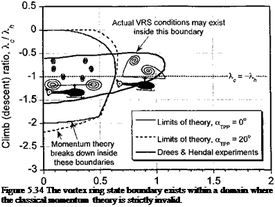
Instrumented flight tests documenting the VRS behavior of helicopters are sparse, mainly because it is a difficult flight condition to sustain any form of equilibrium flight. The flight tests of Brotherhood (1949), Stewart (1951), and Scheiman (1964) have documented the highly unsteady blade loads and high rotor power requirements found during flight in the VRS. Several researchers have conducted laboratory tests with rotors operating in the VRS, although few detailed flow field measurements have actually been obtained. This has been paralleled by some limited modeling efforts to predict the flight boundaries for the onset of VRS, mostly using forms of the classical momentum theory – see Wolkovitch (1972), Heyson (1975), Peters & Chen (1982), Newman et al. (2001), and Prasad et al. (2004). While momentum theory seems to predict a reasonable lower bound of the time-averaged induced velocity at the rotor disk and also the average induced power requirements, but it is not a rigorous approach to the problem. Momentum theory based models are deficient in predicting the conditions leading to VRS because of the ambiguity in defining a single flow direction and a well-defined slipstream boundary over which to apply the governing

Forward speed ratio, i / X

Подпись: Figure 5.34 The vortex ring state boundary exists within a domain where the classical momentum theory is strictly invalid.

equations, this issue already having been discussed in Chapter 2. This problem is illustrated in Fig. 5.34 in terms of the combination of normalized rates of descent and forward flight velocity over which momentum based theories become strictly invalid, along with the VRS boundary estimated from the classic experiments of Drees & Hendal (1951).

Another limitation with the momentum theory is that it does not provide any indication as to the effects of rotor geometric parameters (e. g., number of blades, rotor solidity, blade planform, or twist) or rotor configuration (e. g., conventional, side-by-side, tandem over­lapping etc.) on the VRS problem. This is a significant deficiency that must be treated by alternative mathematical models of VRS, such as based on vortex theory – see, for example, Leishman et al. (2002). It would seem that because VRS is a nonlinear function of rotor disk loading, amongst a host of other operational and geometric parameters, it would seem unwise to generalize results obtained from tests on one rotor or any given helicopter in an attempt to predict the behavior of another helicopter. The inherent flow complexity of the VRS would seem to pose a good practical problem for advanced computational fluid dynamics methods, although the challenge has not yet been taken up except using vortic – ity transport methods (see Sections 14.3 and 14.10.7). One difficulty is in preserving the fidelity of the wake to older wake ages, the wake dynamics being inherent to the problem of VRS. Further discussion of the VRS problem using free-vortex methods is made in Section 10.10.

Quantification of VRS Effects

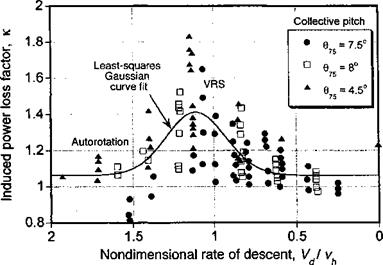
Washizu et al. (1966) have quantified the increased induced power measured during equilibrium descent through the VRS in terms of a power loss factor, к, where

Подпись: (5.95)Pi _ CPi T Vi СтХ,-

where Pi is the induced part of the rotor power and u, refers to the average induced velocity through the rotor as given by the simple momentum theory (see Chapter 2). The induced velocity can be determined from an estimate of the induced power, which is obtained from the measurements of total shaft power by assuming that the profile power, Po, is a function of the rotor thrust alone and does not depend on Vc, that is, in an approach similar to that given in Section 2.13.3 to define the induced power curve in the region where momentum theory is invalid. However, this approach is only approximate and stall effects (which may be produced as a result of the high angles of attack inboard on the blades at high rates of descent) may need to be accounted for. The induced power can then be calculated by subtracting the profile power and loss of potential energy per unit time from the total measured power using C/> = Cp — Cp0 — XcCt, from which the average induced velocity ratio can be obtained from A., = CpJCj – The induced power loss factor then follows from Eq. 5.95 and is essentially a measure of the extra induced power required by the rotor as compared to the momentum theory solution to produce thrust as it descends into its own vortical wake.

The measured values in Fig. 5.30 show the variation of к as a function of descent velocity, where it is noted that a maximum induced loss occurs for this helicopter rotor configuration around a nondimensional descent rate of Vd/vh ^ 1.2 (Vc/vh ^ —1.2). This is consistent with flow visualization and other experimental evidence shown in Section 2.13.6, which suggests that this condition is deeply into the VRS. It is clear also that in autorotation, which is where Vd/vh ^ 1.9, the rotor returns to having a fairly low induced power factor.

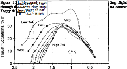
The VRS is accompanied by an extremely unsteady (aperiodic) flow field surrounding the rotor. This behavior is illustrated by the experimental results of Yaggy & Mort (1963), as shown in Fig. 5.31, where the measured rotor thrust fluctuations for a rotor in vertical descent are plotted as a percentage of its mean thrust. At low rates of descent notice that the data essentially collapse to a single curve for all values of disk loading. Because rotor thrust fluctuations in VRS are produced by interactions with its own wake as it comes close to the rotor, then the amplitude of the fluctuations should be related to the mean thrust.

Quantification of VRS Effects

Figure 5.30 Measured induced power factor in vertical descending flight through the vortex ring state. Data source: Washizu et al. (1966).

Quantification of VRS Effects

Nondimensional rate of descent, VJ v.

a h

Therefore, a correlation with disk loading at low rates of descent is to be expected. Notice that the thrust fluctuations build up rapidly as the vertical rate of descent increases, reaching a maximum at Vj/vh ~ 1.2. Thereafter, the fluctuations decrease rapidly as the rotor enters into the turbulent brake state (TWS) and then the windmill brake state (WBS), where the wake is now expanding above the rotor (see also Fig. 14.18).

The experimental results in Fig. 5.31 show a marked dependence on disk loading near VRS, a point discussed by Brown et al. (2002). Disk loading and blade loading (the latter which is related to mean lift coefficients and so to stall proximity) are proportional for a given rotor, and so the observed change in rotor loads with disk loading suggests that the measured data probably contains some evidence of blade stall. This effect is much less clear from the results of Washizu et al. (1966) or Betzina (2001) because there are insufficient data to allow for an interpolation of points to constant values of disk loading. Nearly all of the VRS data in the literature have been obtained from subscale model rotor tests at fixed collective pitch. This makes it difficult to isolate the effects of blade loading on the rotor aerodynamics in the VRS, so to predict how VRS may differ for different rotor configurations (i. e., rotors with different geometric characteristics). However, in nearly all cases the peak amplitude of the unsteady thrust fluctuations lies close to the conditions where the rate of descent is equal to the induced velocity through the rotor.

Yaggy & Mort (1963) also show that a rotor with larger blade twist exhibits larger thrust fluctuations in the VRS. Blade twist affects the distribution of induced velocity over the disk, the position of the tip vortices in the wake and, therefore, the points over the disk that first approach VRS conditions. Leishman et al. (2002) also made this point based on theoretical arguments of wake stability and the onset of wake breakdown in descending
flight. Therefore, it would seem that attempts to generalize the behavior of a rotor as it approaches VRS without reference to the interdependent effects of disk loading or geometric parameters (such as blade planform and blade twist) would be inappropriate.

As previously mentioned, the conditions leading to the onset of the VRS may be obtained under a number of different flight conditions, including situations in forward flight where the rate of descent is low but the disk AoA is high. For example, this situation could be obtained operationally during certain types of maneuvers, such as descending pull – ups at moderate to high airspeeds. Unfortunately, there are fewer experimental results for these conditions: Yet, both the flow visualization of Drees & Hendal (1951) and the thrust nuciuauons measurements оі raggy вс ivion anu oetzina suggest tnat trie

strongest unsteady VRS conditions can be obtained at high rates of descent but with some small forward speed (i. e., a small edgewise component of flow velocity parallel to the disk). The problem, however, is the accurate determination of the induced velocity through the rotor under these conditions.

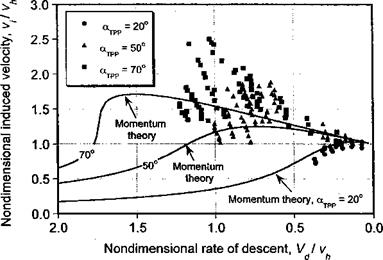
For an inclined descent when the AoA of the disk is otypp, the velocity components normal and parallel to the rotor disk are — VcSinotTpp and Vc cos ajpp, respectively. The results for the induced velocity through the rotor are shown in Fig. 5.32 for a range of AoA. It is interesting that the measurements follow the same trend as given by the momentum theory (Section 2.14.4), although this should not be construed as an endorsement of its applicability in this regime. Momentum theory does, however, underpredict the value of the induced velocity and clearly does not predict the inherent unsteady fluctuations, which is of course a fundamental characteristics of the rotor flow state when in the VRS. Notice that the fluctuations drop off quickly as the disk AoA decreases below 50° and is consistent with piloting experience on helicopters, which shows that a forward speed component causes the rotor to quickly exit the VRS. The results in both Figs. 5.30 and 5.32 are useful in that they provide the analyst with at least some quantifiable basis for estimating the rotor power requirements in steeply descending flight and possibly determining the flight conditions that may result in the phenomenon of “power settling” for a specific type of helicopter.

Quantification of VRS Effects

Figure 5.32 Estimated induced velocity in inclined descending flight. Data source: Washizu et al. (1966).

Quantification of VRS Effects

Figure 5.33 The boundary where vortex ring state is encountered is limited to low air­speeds and high rates of descent. Notional data only – does not represent any particular helicopter.