Category The Aerodynamic Design of Aircraft

Overall thrust forces

3.5 The general principles of the production of a propulsive force in aeronautical engineering are easily understood and can be described almost in a nutshell. Imagine a man in a vehicle which he wishes to propel forward. Without using reaction forces obtained by direct contact with the ground, he can either throw backward masses which are stored in his vehi­cle or seize masses from his surroundings (such as water, by means of oars) and set them in motion backwards. In either case, he will utilise as his pro­pulsive force the force of reaction associated with the change of momentum of the masses. The first method is the basis of rocket propulsion, which we shall not discuss here; the second method is the basis of airbreathing propulsion: an aircraft draws air from the relative wind, supplies it with energy, and then discharges it backwards with increased velocity in a jet.

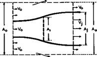
To determine the thrust force of an isolated engine, i. e. the force component on it in the direction of motion, we can apply the momentum theorem to the force and momentum components in that direction. In principle, (3.2) applies. To see the essentials of the flow clearly, we can think of the engine as being a disc of area, situated at the origin*’, at which the energy of the air that flows through it is changed. We want to consider only the changes in the x-direction, and the velocity components other than those in the direction of the mainstream are ignored. We assume that no mass is added during the change of energy. The type of flow to be considered is sketched in Fig. 3.13 (as it is drawn, the thrust would be negative!). The velocity of the air which pas­ses through the engine is Vq far ahead and V – far behind in the Trefftz plane at x = “. Mass flow PqVqAq per unit time enters the control surface through the upstream face with the velocity Vq and entering momentum PqVqAqVq.

^In this coordinate system fixed in the disc, the thrust Th does not perform any work. This is permissible, however, since, when the need arises, we know that, in a coordinate system fixed in space, the propulsive work per unit time is Th x Vq.

The leaving momentum of the mass pjV•A. in the jet is p-V-AjVj and that of the air which leaves the control surface through the area JAq-A- in the Trefftz plane is Po^o^O “ Aj)Vq • This assumes that the energy addition

Overall thrust forces

Fig. 3.13 Flow and control surface around a disc where energy is changed

leaves no permanent changes in the outer stream (such as shockwaves), which is not always true, as we shall see later. There is a further contribution to the momentum changes from the air which is pushed out of the sidepanels due to the expanding flow within the cylinder (in a case like that drawn in Fig.3.13). By continuity, the mass flow per unit time, which leaves in this way, must be (p0V0 – pjVj)Aj. We may assume the diameter of the cylinder to be so large that the axial component of the fluid velocity at its surface is Vq; then the third term corresponding to the momentum leaving the cylinder is (p 0V0 – PjVj> xAjVq. Thus the whole rate of change of momentum and hence the thrust force is

Th = PjVjA^Vj – VQ) , (3.50)

observing that pjVjAj = P]V]A]_. (3.50) states that a positive thrust is pro­

duced when a true jet with V – > Vg is formed. The result can be put simply: the thrust is equal to the increase of momentum of the air which passes through the engine per unit time. It also means that, in whatever form energy is sup­plied, it must in the end be transformed into mechanical work.

A true jet can occur only if the kinetic energy of the jet is higher than that of the air outside it. To achieve this, energy must be supplied to the jet­stream from the surroundings and work must be done on it. Therefore, we must look into the question of how this can be done in flouring media. Energy is usually supplied in the form of heat, and the production of meohanioal work out of a supply of heat is the main purpose of a propulsion device. There are two possible ways in which work can be done continuously by changing the state of the medium: (1) The same medium is made to undergo the same changes of state periodically; the medium goes through a olosed oyole and always returns to the initial state. (2) Successive quantities of the medium are made to un­dergo the same changes one after another, as in steady flow processes; this may be called an open flow oyole or flow process. The latter case is our main concern here (the treatment presented here follows closely that by D KUchemann & J Weber (1953) and (1966); further details can be found there; for a funda­mental treatment of technical thermodynamics and its applications see e. g. E Schmidt et al. (1975)).

3.4 Lifting bodies with shockwaves

For lifting bodies flying at supersonic speeds, several additional drag terms are associated with the generation of lift and with the fact that the body will have a non-zero volume. Some gene­ral relations can be obtained again without specifying how the lift and drag forces are actually produced, following lines of argument similar to those outlined above for the vortex drag. The general relation (3.2) still applies at supersonic speeds and also the expressions (3.7) and (3.8) for the lift and drag forces. But shockwaves and other disturbances now reach the sidepanels III of the control surface of integration in Fig. 3.1, and account must be taken of the fact that the disturbances are generally such that the entropy of the air is increased when it passes through them. Again, many assumptions and concepts must be introduced before relations can be derived which can be used in practice. We shall list only the main assumptions here and give the final results which will be needed below. Details may be found in H Lomax (1955) ,

W R Sears (1955), К Oswatitsch (1956). In particular, we want to establish some relations for the drag terms which can be used as convenient standard units (see e. g. D KUchemann (1962)).

Although we are mainly interested in flows about bodies which cause strong shockwaves, some useful information may be obtained by making the assumption that the body causes only small perturbations in the air and that these are propagated along Maeh lines without any dissipation up to infinite distances from the body. Mach lines are inclined to the mainstream direction at an angle u such that

sin u = 1/Mq or cot у = (MQ2 – 1)^ = 8 • (3.43)

Any entropy increases are assumed to be so small that they can be ignored. We must expect that such drastic simplifications will not be adequate in many practical cases; nevertheless, the functional relationships for the pressure drag obtained in this way may still give a useful guide to what actually hap­pens. Since the perturbations may be regarded as wave motions, the correspond­ing drag forces are called wavedvags.

For Mq > 1, there is a wavedrag associated with the volume Vol of the body, which can be written in the form

– _ 128 Vol2 „ _ ^28 2 (3.44)

CDW it gJ4 О ТГ £4 0 ‘

This indicates that the square of the volume and the inverse of the fourth power of the overall length are dominant; and that volume is at a premium at supersonic speeds and that it should be distributed over as great a length as possible. It is often convenient to use the non-dimensional volume parameter t = Vol/S3/2. K0 is a wavedrag factor which will be discussed further below.

Подпись: CDLW Подпись: _L R252V_ 2TT %2 3 СЛ Подпись: (3.45)

Another wavedrag is associated with the lift of the body. This can be written in the form

which indicates that the inverse of the square of the lifting length of the body is a dominant parameter, together with the square of the lift coefficient, as in the relation for the vortex drag. Whereas the Mach number does not affect the wavedrag due to volume, in this approximation, it appears in the relation for the wavedrag due to lift in the factor g, so that this drag term increases with the Mach number, being zero at Mq = 1.

The constant factors in (3.44) and (3.45) have been chosen in such a way that the values of both Kq and are unity for certain volume and lift distri­

butions which give minimum wavedrag according to linearised theory under cer­tain conditions. In those cases, a reversibility theorem applies, which indi­cates that the lengthwise distributions of volume and lift should show the same aspect for two opposite directions of flight. This means that they have fore-and-aft symmetry, in contrast to the case of minimum vortex drag where the spanwise lift distribution should have lateral symmetry. Thus Kq = 1 is obtained for the Sears-Haack body of revolution, derived by W Haack (1941) and W R Sears (1947); and Ку = 1 is obtained when the load is distributed ellip­tically along the length, corresponding to the lower bound for the wavedrag, derived by R T Jones (1951) and (1952). As in the case of the vortex drag fac­tor Kv, these values of unity are not true minima and values greater or smal­ler than unity may hold in actual cases. Further, the drag factors need not be constants; for example, Kq may vary with the Mach number, after all, and Ky may vary with C^. As long as this is recognised and borne in mind, these drag relations may be used as convenient guides.

Подпись: DF Подпись: _L ?2K + і2» SI A +11 B2C2K. irA IT „4 K0 2ir „2 3 VW Подпись: (3.46)

Finally, we make the assumption that the four drag terms from (3.42), (3.44), and (3.45) are mutually independent and additive so that we can write for the overall drag

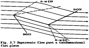
Подпись: Fig. 3.7 Supersonic flow past a twodimensional flat plate

This relation allows us to make estimates of the aerodynamic efficiency L/D, which appears in the general performance analysis discussed in Section 1.2. It will be used again later as a basis for the performance analysis of various types of aircraft.

Подпись: C P Подпись: ± 2 3.4 Lifting bodies with shockwaves Подпись: (3.47)

We can now look at some flow patterns which are typical for supersonic Mach numbers, again with a view to finding some that are suitable for engineering applications. An instructive example is a twodimensional flat plate which is placed at a small angle of incidence a to an inviscid supersonic stream. Although we shall find later that we cannot see any worthwhile aircraft appli­cations for this type of flow, it can help to explain some properties of supersonic flows, as a counterpart to the corresponding incompressible flow in Fig. 3.3. The supersonic flow is shown in Fig. 3.7. Since the leading edge cannot have an upstream influence, the attachment line lies along the edge, so that there is no flow around the leading edge and no need to round it off, as in subsonic flow. But, as a consequence, a suction force at the leading edge, as given by (3.30), does not occur, and this is the origin of the wave – drag due to lift. There is an oblique shockwave on the lower surface and a Prandtl-Meyer expansion fan on the upper surface, both of such strengths that the flow is deflected through the angle a. Downstream of the leading edge, flow direction and pressure remain constant until the trailing edge is reached. There, the pressure is equalised by means of a shockwave on the upper surface and a Prandtl-Meyer expansion on the lower surface, turning the flow back into the initial direction. We note that the Kutta condition of smooth outflow is not fulfilled. But there is no need for this since a viscous flow could, in principle, negotiate the flow deflection. Clearly, the pressure is higher than the ambient pressure along the lower surface and lower along the upper surface. Conceptually, this is a very obvious way of generating a lift force. The equivalent of the lift is found in the downward momentum of the air which has been subjected to the waves. In a linearised treatment, first carried out by J Ackeret (1925), the pressure coefficient is given by

Подпись: 4 sin a A77 3.4 Lifting bodies with shockwaves Подпись: (3.48)

and hence the lift and drag coefficients by

so that the lift-to-drag ratio is

L/D = cot a. (3.49)

This drag is all wavedrag due to lift, as defined above (but note that this twodimensional flow leads to a value of Ky which is not constant (= J тг/В) ). In the absence of a suction force at the leading edge, the resultant force is normal to the plate and not normal to the flow direction, as in the corres

It is clear, even from these specific results, that the supersonic flow past an unswept wing differs fundamentally from the classical subsonic aerofoil flow, so that an aircraft designed on these two different principles to fly at both subsonic and supersonic speeds would experience radical changes in its characteristics during flight. Although such aircraft have been built, they do not conform to our general design principles and we search, therefore, for another type of flow which suits our purpose better.

We shall see later in Chapter 8 that typical aircraft to fly at supersonic and hypersonic speeds should be threedimensional lifting bodies and essentially different in shape from classical aircraft with wings of considerable lateral
extent. A simple method for constructing such lifting bodies has been sugges­ted by T R Nonweiler (1963). Parts of known flowfields are used, and we con­sider next an example which will lead to the third basic type of flow to be used in aircraft design (for a general survey of these matters, see e. g.

D KUchemann (1965)).

We begin with the supersonic inviscid flow past a twodimensional wedge, the top of which is parallel to the mainstream, as indicated in Fig. 3.8. This body causes only one disturbance, a plane shockwave which is attached to the

3.4 Lifting bodies with shockwaves

Fig. 3.8 Supersonic flow past a twodimensional wedge

leading edge. The flow is like that over the front part of the lower surface of the flat plate in Fig. 3.7. The pressure behind the shockwave is constant and exact values are known, depending on the deflection angle and the Mach num­ber. The design principle is now to form solid surfaces from the streamlines of the flow. If such surfaces extend up to the shockwave, the overall flow is not changed. We then have a threedimensional lifting body with an open base, which has the undisturbed pressure over its top surface and a uniform pressure over its lower compression surface, which is higher than the ambient pressure.

A piece of the initial plane shockwave is contained between the leading edges. This feature imposes the condition that the leading edges are aerodynamically supersonic, that is, the velocity component normal to the leading edge must be greater than the velocity of sound.

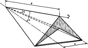
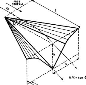
Aerodynamically, the simplest of these bodies is one where the compression sur­face is formed by two plane surfaces intersecting at a ridge line which lies in the lower surface of the initial twodimensional wedge. With the upper ridge line lying in the mainstream direction, this body has a cross-section like an inverted V, as indicated in Fig. 3.9. These wings are sometimes called

3.4 Lifting bodies with shockwaves

Fig. 3.9 Caret wing supporting and containing a plane shockwave. After Nonweiler (1963)

accpet wings. They have a delta planform.

Nonweiler’s concept of starting with a known shock shape and determining a threedimensional body which supports and contains it between its leading edges is not restricted to this simple kind of conical body with flat surfaces and a single plane shock. For instance, L H Townend (1963) has suggested starting

3.4 Lifting bodies with shockwaves

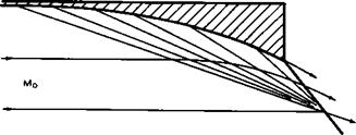
Fig. 3.10 Curved wedge surface with centred compression

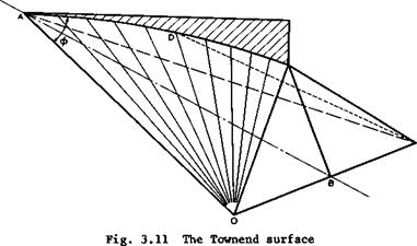
from a basic flow which incorporates an isentropia compression through an in­finite number of infinitely weak shockwaves coming from a twodimensional cur­ved wall. A simple flow of this kind is obtained by reversing the Prandtl – Meyer expansion flow. The resulting flow past such a curved wedge is sketched in Fig. 3.10. From this, a compression surface with straight leading edges

3.4 Lifting bodies with shockwaves

can be constructed, taking the curved shape of the initial wedge as the lower ridge line. As shown in Fig. 3.11, the two halves are ruled surfaces, genera­ted by straight lines radiating from the wing tips. A range of designs is possible between the isentropic and the single-shock compressions. An exten­sion to more general curved surface shapes has been made by J G Jones et at.

(1966) , who start with the flowfield of a right circular cone at zero angle of incidence and use part of the initial conical shockwave. The simplest shape of this kind is the half-cone underneath a thin flat delta wing, with the coni­cal shockwave attached to the leading edges, as proposed by A J Eggers (I960)). There is thus a great variety of shapes that can be designed to generate lift by means of shockwaves. In every case, the inviscid flow is known exactly.

For obvious reasons, a descriptive generic term for lifting bodies of this

kind is waverider. They exhibit the third basic type of flow for generating lift forces. These matters will be discussed in more detail in Section 8.2.

A further generalisation can be made by designing the top surface of such lift­ing bodies in a similar way from known expanding flowfields. J W Flower (1963) has constructed a simple shape from the twodimensional Prandtl-Meyer expansion where the flow is deflected through an angle 6. Sections of this flow may be put together as indicated in Fig. 3.12 such that the leading edges of the three­dimensional expansion surface lie along the first characteristic surface and issue from a chosen apex. The surface downstream of the leading edges is

3.4 Lifting bodies with shockwaves

PLANE CONTAINING TRAILING EDGE

Fig. 3.12 Flower’s expansion surface

formed by the streamlines of the twodimensional flow which pass through the leading edges; hence the surface is curved first and then plane. The keel of the surface is straight and inclined downward from the mainstream direction.

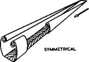
Lastly, non-lifting volume-producing bodies can also be designed according to these principles. This has been suggested by G I Maikapar (1959) who obtained symmetrical bodies with star-shaped cross-sections and plane shockwaves con­tained between the edges and joining the tips of the stars.

Although the effects of viscosity pose many problems in the design of wave – rider aircraft, there is, in general, no particular difficulty in fitting a viscous layer into the inviscid design flows without upsetting their essential features. There are displacement effects, especially near the leading edges, but these need not change the general flow pattern. Exceptions to this are compression surfaces where the pressure is not uniform, as in the flow past a Townend surface. There, the boundary layer develops spanwise crossflow velo­cities even though the external streamlines are straight in planview.

Design problems arise mainly in fitting compression and expansion surfaces to­gether and also in the shaping of the backend. These problems are closely re­lated to detailed aircraft requirements and also to the way in which propul­sive forces are incorporated into the design. These matters will be discussed later in their proper contexts in Chapter 8. The same applies to the whole complex of problems arising in off-design conditions, which are of consider­able practical importance.

In general terms, waveriders are a type of aircraft where the means for pro­viding volume3 lift, and propulsion are so closely integrated that their effects cannot readily be separated from one another. For example, it is impos­sible to say whether the wavedrag of a caret wing is caused by its volume or by its lift. For the same reason, an "aerofoil theory" like that for the clas­sical aircraft described in Section 3.2 cannot readily be derived. In prin­ciple, (3.7) and (3.8) for the lift and drag forces still hold, but it is no longer possible to simplify them on the assumption that the perturbations are small. Also, the farfield of the lifting body of finite span and length would have to be determined, including all the essential non-linear effects. This has not yet been done; it is probably a more difficult undertaking than the direct determination of the nearfield. Thus it would appear that the farfield approach is not attractive in this case, and that the forces and moments act­ing on such a body can be obtained more conveniently from the pressures over the body surface. The discussion of these matters in Chapter 8 will follow these lines.

Slender wings with non-planar vortex wakes

3.3 With regard to the question of how lift forces can actually be generated, we have so far identified only one basic type of flow, the classical streamline flow past aerofoils. On a threedimensional wing, this is associated with separation from the trailing edge only and the formation of a trailing vortex sheet which is nearly plane, at least initially. There are, however, other useful flows and an alternative type of flow is one where separation from side edges is an essential feature and where the trailing vortex sheet is essentially non-planar. One such flow has been shown in Fig. 2.16 where the vertical extent of the trailing vortex sheet is very pronounced because the side edges are much longer than the trail­ing edge on this rectangular wing of very small aspect ratio. Intuitively, one would expect that the extended non-planar vortex sheets should accelerate a greater mass of air downward and hence produce more lift than the plane vor­tex sheet from the trailing edge only, for the same span and angle of inci­dence. As we shall discuss in more detail in Section 4.6 and in Chapter 6, this turns out to be true. The lift is then a non-linear function of the angle of incidence, and (3.28) no longer applies. Also, the vortex drag for a given span and overall lift may be smaller, that is, the value of Ky can be smal­ler than unity in this case. In principle, then, this is another basic type of flow suitable for generating lift forces.

In practice, the particular flow shown in Fig. 2.16 does not fulfil all the requirements which would make it suitable for engineering applications. We have already seen that it responds readily to disturbances and might become asymmetrical. Therefore, we are looking for flows which produce acceptable and stable arrangements of non-planar vortex sheets. There are many of this type, all associated with so-called slender wings whose semispans s are sig­nificantly smaller than their overall lengths t. s/l = 1/4 is a typical

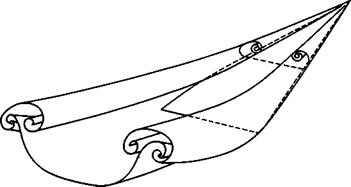
value. Fig.3.5(a) shows an example where separation occurs along the side and trailing edges of a tapered wing but where the flow remains attached over the leading edges. Since we have already seen in connection with Fig. 2.5 that such an attached flow is difficult to achieve when the angle of sweep of the leading edge is high, we may design for a separated flow instead by making the leading edges aerodynamically sharp. The resulting flow is then typically like that sketched in Fig.3.5(b). Carrying the abstraction one step further, we arrive at a conical flow with two large rolled-up vortex cores growing above the wing. On a complete wing, as shown in Fig. 3.6, the flow may be essentially conical over the front part. This flow fulfils the engineering requirements we have; it may be regarded as the archetype of the second basic type of flow. The corresponding types of aircraft will be discussed in Chapters 6 and 7.

This type of flow with coiled leading-edge vortex sheets over slender wings can exist at subsonic as well as supersonic flight speeds, and so a slender aircraft can be designed to have the same type of flow throughout its flight range. At supersonic speeds, the leading-edge vortex sheets may be relatively weak, and a slender wing may be so designed that the sheets vanish at the cruise condition and the attachment line lies along the leading edge. One

Slender wings with non-planar vortex wakes

a TAPERED WING WITH TIP VORTEX SHEETS

Slender wings with non-planar vortex wakes

b SLENDER DELTA WING WITH SPIRAL LEADING-EDGE VORTEX SHEETS

Fig. 3.5 Wings with flow separation from side edges

Slender wings with non-planar vortex wakes

Fig. 3.6 Model of the flow past a lifting slender wing. After R L Maltby

condition for this type of flow to exist at supersonic speeds is that the leading edges should lie well within the Mach cone from the apex, that is, the leading edges should be nominally subsonic in that the component Mach number normal to the leading edge remains subsonic. If the leading edges were to approach the Mach cone, the flow would change from the design type sketched in Fig. 2.8(c) to that sketched in Fig. 2.13 (albeit with sharp leading edges).

In principle, the lift and drag forces acting on these slender wings can be determined from the general relations (3.7) and (3.8). We may also assume that the perturbations caused by the wing are small. A theory based on this assumption will be described in Section 4.9 and Chapter 6 and used to show that these wings also operate best at supersonic speeds if their leading edges

lie well within the Mach cone from the apex so that the practical design con­ditions are indeed consistent with the type of flow that has been assumed.

Aircraft may be designed to have either of the two basic types of flow we have identified so far for flight at subsonic speeds and also at supersonic speeds. But it will become increasingly difficult to keep the perturbations small, as is required in these flows, as the Mach number of flight is increased. There­fore, we must look for yet another type of flow which incorporates shockwaves and expansions.

Wings with near-planar vortex wakes

3.2 . To begin with, we assume that the trailing vortex sheet, including its rolled-up edges, has ceased to grow in space or in time when it reaches the Trefftz plane. Otherwise, the general relation (3.2) would have to include the appropriate time-dependent terms.

This assumption can never be strictly true in an inviscid flow, but we may be content with the assurance that any growth is so slow that it can be neg­lected. In any case, viscous effects may have modified the structure of the vortex sheet and its flowfield, and we are prepared to ignore these, too. We may then assume that the vorticity vector in the sheet lies along the direction of the mainstream. The sheet takes no forces and hence intersects the Trefftz plane at right angles. It follows that the sheet induces only lateral velo­city components, a sidewash Vyxr and a downwash vz^r, and that vx ■ 0 in the Trefftz plane. This leads to important simplifications if we also make use of the fact that some of the integrals over the sidepanels in (3.7) and

(3.8)

Wings with near-planar vortex wakes

can be made to vanish if we make the further assumption that the velo­city perturbations are smalt. The sidepanels may then be moved out far enough for square terms in the perturbation velocities to be so small as to make no contribution. Thus the integrals involving vz^ and vzv in the second term of (3.7) vanish; similarly, the whole of the second term in (3.8) vani­shes. The expressions for the lift and drag forces from (3.7) and (3.8) now take the form

We note that the lift force is associated with the downwash in the Trefftz plane and with pressure differences over the horizontal sidepanels, whereas the drag force is manifested as a pressure integral over the Trefftz plane.

Подпись: P - Pc Wings with near-planar vortex wakes Подпись: (3.11)

Next, we use the gasdynamic equations for the relation between pressures and velocities, in particular, Bernoulli’s equation (2.12) for perfect gases. For small perturbations, the leading terms in a power series of these perturba­tions are

p/p0 = 1 – Mq2 vx/Vq. (3.12)

For the flow considered, p = pq in the Trefftz plane, according to (3.12), since vx = 0. Thus the Mach number does not appear explicitly in the rela­tions for lift and drag, even though the flow is assumed to be compressible. (3.11) and (3.12) can be inserted in the first term of (3.9). In the second term of (3.9),

P " Po “ – Pqvovx at z = ±A,

Подпись: L Wings with near-planar vortex wakes Wings with near-planar vortex wakes Подпись: dy Подпись: (3.13)

according to (3.11), to a first order. The relation for the lift then becomes

This can be further simplified if we introduce the perturbation velocity potential ф(х, у,г), analogous to (2.1). (3.13) can then be written as

+B

L = PqVq I" Аф (y)dy, (ЗЛ4)

where Дф * фц – фд is the difference between the potential functions on the two sides of the trace of the trailing vortex sheet in the Trefftz plane. Thus the load over the body is related directly to the potential difference across the vortex sheet which the body leaves behind.

The pressure difference p – pQ in the Trefftz plane, which appears in (3.10) for the drag, can be approximated by

P – P0 “ – *Po(vy2 + vz2> >

according to (3.11). The relation for the drag then becomes

+A +B

D * ip0 I I [vy + vz] dydz ’ (3.15)

-A -B x““

which can be rewritten as

5 ‘ h°l І [(^) *(&)] ^ • <3-’6>

where the velocity potential is introduced again. Next, we assume that 3vx/3x is also zero in the Trefftz plane, in addition to vx _ 0, so that ф obeys the potential equation also for a hypothetical twodimensional flow in the Trefftz plane:

3jt+ „ о, (3.17)

2.2

3y 3z

which is a special form of (2.28). Further, we apply Green’s theorem to re­place the double integral in (3.16) by a contour integral over the outer
surface of the trace in the Trefftz plane. We then have

Wings with near-planar vortex wakes(3.18)

where n is normal to the trace and о is along it.

With (3.14) and (3.18), we have expressed both the lift force and the drag force in terms of the values of the velocity potential at the trace of the trailing vortex sheet in the Trefftz plane. If we know the shape of the trace, we can determine the potential function along it and then derive a direct re­lation between lift and drag on the body. The actual calculations are still rather complicated (see e. g. A Robinson & J A Laurmann (1956)); an instruc­tive case has been treated by J H В Smith (1960). Further subtleties arise from the fact that the drag is a second-order quantity. W R Sears (1974) has pointed out that, strictly, it is necessary to account for the first-order downward deflection of the vortex wake but that, when this is done, the clas­sical results derived here remain true, as it happens. Sears’s short paper should be studied carefully to understand fully the implications of the Trefftz-plane concept.

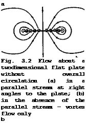
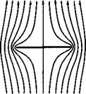
Подпись: a Fig. 3.2 Flow about a twodimensional flat plate without overall circulation (a) in a parallel stream at right angles to the plate; (b) in the absence of the parallel stream - vortex flow only b
Wings with near-planar vortex wakes

This lift-dependent vortex drag has a minimum value for a wing of given over­all lift and span when the downwash vzTr “ – v in the Trefftz plane is constant along the trace of the trailing vortex sheet, as was shown by MM Munk (1919). For that case, the potential function ф(у, г) in the Trefftz plane can be determined by considering the trace as a solid body put into a twodimensional parallel flow with the velocity vz^r far below it. A simple and important particular solution is obtained when the trace is assumed to be a straight line at z = 0, extending from у = – s to у = +s. The flow

is then like that sketched on the lefthand side of Fig. 2.14(b) and is shown

(3.19)

Подпись:(3.20)

where the plan form area S and the aspect ratio A = 4s /S of the wing have been introduced. Similarly, the drag on the body can be worked out from (3.18), which gives

r8 v fS

5 – ір0 f A<f,(y)vzTrdy = ipovo“^ j Лф<іу

Подпись:5 = і l

2 V.

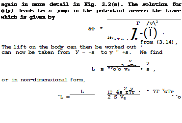
Подпись: by (3.14).Combining (3.20)and (3.21), we have in non-dimensional form

Подпись: (3.22)s ■

Thus the vortex drag increases with the square of the lift and falls inverse­ly with the aspect ratio. This is an important relation in wing design, and we shall come back to it many times.

Consider now specifically wings of high aspect ratio at subsonic speeds. Hav­ing obtained a solution for the flow in the Trefftz plane behind a wing with a trailing vortex sheet, we can take a next step and determine some properties of the wing itself, especially the flowfield near the wing, which are consis­tent with the results obtained so far. For this purpose, we consider the special case of a flat wing put at an angle of incidence a to the mainstream direction. Moreover, we assume that the chordwise extent, c, is small compared with its span, 2s, i. e. the aspect ratio of the wing is high:

A » 1. This case may be unnecessarily restrictive with regard to some of the properties we shall derive, but it has the advantage of showing the main concepts and features very clearly.

Подпись: ITA CL Подпись: (3.23)
Wings with near-planar vortex wakes

In this case, the downwash is constant over the trace in the Trefftz plane, and the flow in the Trefftz plane is as shown in Fig. 3.2(a). In the absence of the parallel flow, the streamlines of the flow induced by the vorticity distribution along the trace only are shown in Fig. 3.2(b). The downwash vzTr can be related to the overall lift force by (3.20):

In the Trefftz plane, the elemental vortex lines can be regarded as of infi~ nite length fore and aft. On the wing, on the other hand, the spanwise distri­bution of trailing vorticity is the same as in the Trefftz plane but the ele­mental vortex lines are of semi-infinite length. Therefore, the induced down – wash is only half that in the Trefftz plane:

Подпись:vzW VzTr, J_ о

“i = VQ “ 2 V0 vA L •

Thus the geometric boundary condition on the wing surface is

1 г

«е “ <* " ai “ a – xA L *

where the effective angle of incidence a has been introduced. This is one form of the classical aerofoil equation’, it will be discussed further in Section 4.3.

Подпись: Mx) Подпись: Др Vo Подпись: (3.26)
Wings with near-planar vortex wakes

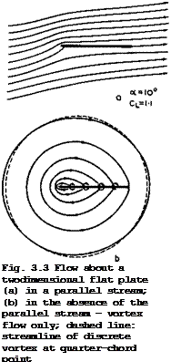
If the aspect ratio is high, the flow in any plane у = constant may be re­garded as twodimensional, as though the wing extended laterally to infinity on either side. This is at best a plausible assumption at this stage, and we shall give a more rigorous derivation in Section 4.3. Here, we may use the solution for the ahordwise distribution of bound vorticity over a twodimen­sional flat plate at an angle of incidence, which is based on the Kutta – Joukowski theorem (2.46). The chordwise loading is then

Подпись: Fig. 3.3 Flow about a twodimensional flat plate (a) in a parallel stream; (b) in the absence of the parallel stream - vortex flow only; dashed line: streamline of discrete vortex at quarter-chord point

where xL and xT are the values at the leading and trailing edges respec­tively. The corresponding flow has been discussed in connection with Fig. 2.14(a) and is shown in more detail in Fig. 3.3(a). If the parallel stream

is subtracted, the streamlines induced by the bound vorticity alone are as shown in Fig. 3.3(b). Note that the farfield approaches that of an isolated vortex line located at the quarter-chord point of the plate.

We can derive from (3.26) a relation for the sectional, or local, lift coefficient:

Подпись: L— ■ if *< ЛГс c J rT

Подпись: *povoc* 1.(x)dx = 2тга = C, . (3.27)

Подпись:Thus the sectional lift elope CL/ ae “ 2ir. As indicated, may be regarded as constant along the span when A » 1, and thus equal to the overall lift coefficient CT

(3.28)

which is a very simple relation for the overall lift elope of the wing. This approaches the sectional value from (3.27) as A tends to infinity.

It is consistent with this model of the flow that the resultant air force is normal to the effective flow direction but not to the actual geometric flow direction. Hence the existence of a drag component in the direction of the mainstream. It is instructive to resolve the resultant air force into the components Cjj and Gj normal and tangential to the chordline of the wing according to

Подпись: (3.29)CT “ “ = – uCL + Cp

Подпись:

Wings with near-planar vortex wakes

Cjj = CL + aCD

which is even simpler than the drag relation (3.22) in that the aspect ratio does not appear (see D Klichemann (1940)). The minus sign is to indicate that the tangential force is directed forward. The question then arises of how such a euotion force can be realised in a practical flow.

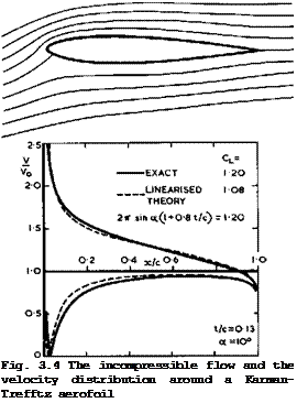
In deriving the solution for the chordwise bound vorticity distribution, we have already seen to it that the Kutta condition of smooth outflow from the trailing edge is fulfilled. Now we have to consider what to do with the flow near the leading edge where the load and the velocity are infinite: an infi­nite pressure over an infinitely small area produces a finite suction force, given by (3.30). Such a corner with a turning of the flow through 180° cannot be negotiated without separation by a viscous incompressible flow, and we have to think of how to modify the shape of the wing in such a way that a viscous flow will remain attached and that the suction force is realised at the same time. This can be achieved by rounding-off the noee of the aerofoil so that a finite suction force acts on a finite forward-facing area. In this way, we arrive at the characteristic shape of the alaeeical aerofoil eection. A typi­cal shape of this kind, together with the velocity distribution along the

LIVE GRAPH

Click here to view


The Aerodynamic Design of Aircraft

Подпись: Fig. 3.4 The incompressible flow and the velocity distribution around a Karman-Trefftz aerofoil

surface is shown in Fig.3.4*). Clearly, to negotiate the high turning angle and the subsequent steep adverse pressure gradient is a precarious undertaking for

the air. We also note that, on this particular symmetrical aerofoil, the load is still similar to that over a flat plate: it is far from uniform along the chord and the rear end does not carry much. One would obviously like to de­sign aerofoils which are more heavily and more evenly loaded. We can under­stand now why the design of suitable aerofoil sections is one of the main pro­blems in the aerodynamic design of this classical type of aircraft. This then is the first major* type of flow we have found, which is suitable for genera­ting lift forces.

Подпись: Yt(y) Подпись: ЭДф Эу Wings with near-planar vortex wakes Подпись: (3.31)

Having determined the main characteristic features of the chordwise profile shape, we consider next the question of what the ptanform shape should be, i. e. the spanwise distribution c(y) of the wing chord, which is consistent with the general flow model. We can use the fact here that we already have a solution for the potential difference Дф(у) in the Trefftz plane in (3.19). We now recall that, at the sheet, the tangential velocity component Vy(y) is equal to ±Yt »if Yt is the strength of the vorticity distribution. ^Hence,

*) . . … . This figure shows not only the exact solution for this particular aerofoil

but also an approximate solution according to linearised theory, as discussed

in Section 2.2.

by (3.19). This allows us to link up the vortex distribution in the Trefftz plane with the spanwise load distribution L(y) along the actual wing if we assume that the trailing vortex sheet does not change its shape between the trailing edge of the wing and the Trefftz plane, which is, in any case, im­plied in the preceding analysis. On the other hand, the shedding of trailing vorticity is related to the change of circulation along the span:

Yt(y) = ^5^- . (3.32)

where

PqVqT = L(y) , (3.33)

which follows from the Kutta-Joukowski theorem (2.46). We can now combine the last three equations and obtain for the spanwise load distribution by integra­tion____

CL(y)c(y) = CL/l – (У/s)2 , (3.34)

that is, the spanwise loading is elliptic, falling to zero at the wing tips like a square root of the distance from the tips. For the flat wing con­sider here,.and if we want to be equal to the overall value C^, we must

have

c(y) = ff/l – (y/s)2 . (3.35)

This means that the planform is also elliptic.

We now have a consistent flow model, which has given us relations between the overall lift and drag forces and the angle of incidence as well as relations for the chordwise and spanwise load distributions. We also have some guide­lines for the shapes of the chordwise aerofoil sections and of the wing plan – form. All these apply to a special case but we shall see later, in Section

4.3, that the departures from this special case are not all that large in practice and that the results derived here give some useful clues to the characteristics of classical unswept wings. The results are the essence of the classical aerofoil theory of F W Lanchester (1915) and L Prandtl (1918).

We digress here to consider briefly a physical interpretation of the drag re­lation (3.22), which may help us in thinking about these matters. We intro­duce a fictitious mass flow of air, PqVqS’ , whose rate of change of down­ward momentum far behind the wing is equal to the lift force on the wing:

L = PoV0S’vzTr. (3.36)

The rate at which kinetic energy is given to such air equals the rate at which work is done in overcoming the vortex drag. Thus

DV0 = iP0V0S’vzTr2 * (3*37)

Pohlhausen has shown that S’ in these equations is the same quantity and that it has the value irs^ for the case that the trailing vortex sheet is plane.

In other words, the mass of air that is accelerated downward to produce the lift is equal to the fictitious mass which flows through a circle round the span of the wing with the mainstream velocity Vq. Elimination of S’ from

(3.36) and (3.37) gives (3.21) and elimination of vzjr gives (3.22). On the other hand, we can draw the important conclusion from (3.36) and (3.37)

that a given value of the actual lift L is generated most efficiently (i. e. with the least drag) if the largest possible mass of air is captured (i. e. if the span is as large as possible) and then subjected to the smallest downward acceleration (i. e. that vzjr is as small as possible). This defines one of the basic problems in aircraft design.

Obviously, there are other, non-aerodynamic, reasons why the span cannot be made arbitrarily large, such as the weight of the structure that would be needed. Thus, as will be discussed in more detail in Section 4.1, aircraft design must strike a balance between all the aspects involved. On the other hand, it will not even be necessary to strive always for the best and for per­fection in some or every respect. For example, if a given flight range is to be achieved according to (1.7), and if achievable technological values of the other garameters Hnp and Wp/W are also given, then the aerodynamic para­meter L/D (or L/D) needs to reach only a certain value and not the highest possible. Thus the essence of aircraft design is to reach the required values in an economical way without any unnecessary losses.

Returning now to the relations between lift and drag forces, we note that, although we have applied the arguments to special cases, the derivation of the drag equation (3.22) is not so restricted. It holds for wings of any aspect ratio. Further, the relation can be generalised. If we remove first the restriction to straight traces in the Trefftz plane, we can think of other shapes of the trailing vortex sheet which can still produce a constant down- wash in the Trefftz plane. The drag value can then be smaller or greater than that given by (3^22) but we can expect that the functional relationship bet­ween Cl and Cjj may still be retained. Thus we can write formally for the vortex drag

s – ivJ * <3-38>

where Kv is a vortex-drag factor which can be greater or smaller than unity. Kv = 1 is then only a convenient standard unit to measure the vortex drag.

We note that only specially designed wings will produce trailing vortex sheets which will move downwardat a constant speed under their own influence. If wings produce vortex sheets with rolled-up cores along the side edges, then these cores themselves cannot have a constant downwash all along the sheet. The vortex drag must then be higher than the corresponding minimum value, i. e.

Kv > 1. Since such rolling-up will happen in all practical cases, it is a

matter of some surprise that there are many cases where the actual drag values lie close to the calculated minimum value. The explanation for this may be that the rolling-up process can be rather slow and without appreciable further energy losses, so-that the flowfield near the wing is still dominated by trail­ing vortices which are not yet rolled-up to a significant extent. In other words, the Trefftz plane is then effectively closer to the wing rather than at infinity downstream.

Some specific configurations can be treated analytically in a relatively sim­ple manner. These must be shaped in such a way that the trace of the trailing vortex sheet in the Trefftz plane is the same as the shape of the lifting system in a vertical plane through its trailing edge, i. e. the vortex system must produce a constant downwash along the span of the wing and of the trace in the Trefftz plane. All these configurations then have the smallest vortex drag for a given span and overall lift. The problem is every time to find a

Wings with near-planar vortex wakes

solution for a twodimensional potential flow in the Trefftz plane, where the trace of the trailing vortex sheet is regarded as a solid body in a parallel stream at right angles to it. The method of conformal transformations is usually applied.

Подпись: *V " 1 + h/s so that the lift-dependent drag is Подпись: for h < s Подпись: (3.39)

The cases which have been treated include biplanes, wings with endplates, with fuselages, with several nacelles, and intersecting wings. A summary of results, together with references to the original work may be found in Sections X.14 and XII.11 of В Thwaites (1960). In many cases, the lift-dependent drag factor of non-planar lifting systems turns out to be smaller than unity, but this does not necessarily mean that such a particular lifting system has a better per­formance in practice than, say, a simple monoplane wing that produces the same lift. Consider, for example, a wing with endplates of a height h at the wing tips. According to J Weber (1954), the drag factor can be approxi­mated by

Подпись: 11

DL ТГ 1 + h/s 2s/c L.

Подпись: DL Wings with near-planar vortex wakes Подпись: (3.40)

by (3.38), where c is the mean chord of the wing. This can be rewritten as

which is the same as that of a plane wing of aspect ratio A = 2(s + h)/c.

This means that the vortex drag is about the same whether the span is extend­ed by h on either side or whether endplates of height h are fitted at either wing tip. Thus vertical endplates really pay off aerodynamically in wing design only if they can fulfil another function at the same time, such as serving as fins on a tailplane.

We should also be aware of the fact that any of these lifting surfaces with constant downwash along the span do not give the smallest drag in an absolute sense. For example, if the condition of given span is replaced by another related to achieving the smallest structure weight of the wing, still for a given overall lift, then L Prandtl (1933) has shown that the smallest vortex drag is obtained with a wing planform which is more highly tapered than the ellipse, where the downwash is not constant along the span and the spanwise loading no longer elliptic but falls off more steeply towards the tips. This work has been extended by A Klein & S P Viswanathan (1975) who used more re­fined assumptions about the structure weight.

All these considerations apply to inviscid flow. Viscous regions can readily be fitted into them on wings with attached flow and near-planar vortex wakes. We can expect that, as a first approximation, a viscous skin-friction drag will manifest itself as a momentum deficit in the Trefftz plane. In the simplest case, we may assume that this will result in a drag term

which is independent of the lift force and additive to the vortex drag from (3.38), so that the overall drag is

Подпись: (3.42)S = ^DF + ttA Vl

Alternatively, the value of Сцр can be determined directly by integrating the skin-friction forces over the surface of the body. But this cannot be all the drag due to viscous effects. The displacement effect of the boundary layer, discussed in Section 2.4, also leads to a drag force. This may be called a viscous pressure drag. Since the leading term in this effect may be interpreted as an effective reduction Act of the angle of incidence, the associated drag force can be approximated by AaC^ which, in turn is nearly proportional to and could be hidden in the value of Ky in (3.42), al­

though it has nothing to do with the vortex drag. It is especially difficult to tell the different drag terms apart in an analysis of experimental results.

(3.42) is widely used as a convenient rough measure of the overall drag of aircraft at subsonic speeds. We recall that the Mach number dropped out in the derivation of the original relation (3.22), although lift and drag by themselves must be expected to be functions of the Mach number. Therefore, the relation for the vortex drag is formally applied throughout the whole Mach-number range, including supersonic speeds.

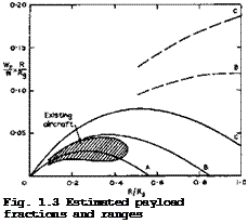
In practice, it is very important to determine the drag forces accurately so as to be able to make reliable predictions of an aircraft’s performance, not only under cruise conditions but also at low speeds. Here, we must still rely on experiments and, since these are generally done on scaled-down models, the fundamental problem of extrapolating windtunnel results to full scale arises.

To solve this, a practicable technique for measuring and analysing drag is needed. Such a technique can be based on (3.42) if the assumption is accep­ted that of the two essentially different components – the profile drag Cdf of (3.41) and the vortex drag Cdv of (3.38) – only the first is expected

to exhibit a marked dependence on the Reynolds number and hence a scale effect. This assumption is consistent with the basic flow model we have in mind; it derives from the manner in which we think the presence of the drag force becomes apparent in the surrounding fluid, where two quite different processes are involved: one related directly to energy losses in the fluid entrained into

the boundary layers and wake of the lifting system; the other to the energy required to maintain the large-scale and predominantly inviscid flow genera­ted by the trailing vorticity. It is really only through their connection with these two processes that the drag components can be said to have been defined. This then leads to the question of how each of the two components can be determined separately, preferably by experiment.

It has justifiably been argued by E C Maskell (1972) that the common practice of measuring only the overall drag and then taking the vortex drag to be pre­dictable by the methods of linearised theory cannot be regarded as a serious attempt at an accurate drag analysis; it is especially suspect in high-lift conditions. An approach to be preferred is that of A Betz (1925) who devel­oped a method for the direct determination of the profile drag from measure­ments in a transverse section of the wake downstream of a lifting wing. The momentum theorem is applied to a control surface bounded upstream and down­stream of the wing by transverse planes and, if the flow is assumed to be steady, incompressible, and irrotational, except within the boundary layer and wake of the wing, then the profile drag integrals involve only velocity
components and total heads and have to be evaluated only over the wake. This has recently been refined by E C Maskell (1972) and extended to admit the de­rivation of a comparable expression for the total drag and its two components. Account is taken also of the constraints imposed on the flow by the presence of the windtunnel walls. This work is still continuing, and further exten­sions to include compressibility, shockwaves, and time-dependent effects are needed before we have a complete method of drag analysis based on wake measurements.

MEANS FOR GENERATING LIFT AND. PROPULSIVE FORCES

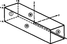
3.1 Overall lift and associated drag forces. Consider now more specific­ally how lift forces can be generated and what this costs in terms of energy to be expended. To begin with, the overall flow characteristics which we can already identified allow us to derive some important general relations and guidelines by the application of the momentum theorem, even without defining in detail how the lift is generated (see e. g. Th von Karman & J Burgers (1935), W R Sears (1955), В Thwaites (I960)). Consider a general lifting body of span 2s, length l, and thickness t (or volume Vol) in a uniform stream of velocity Vo. In a rectangular coordinate system fixed in the body, with x along the mainstream direction, у sideways, and z vertical, we put a large cylindrical control surface S around the body which itself is situated at the origin, as indicated in Fig. 3.1. The upstream face I lies at x = -» and the downstream face II, the so-called Trefftz plane, at x = +» (after E Trefftz (1921)). The plane sidepanels III are situated at

i

z=±A ; – B<y<+B

(3.1)

у = ± В * – A<z<+A.

We have seen that the flow past a lifting body always leads to the formation

MEANS FOR GENERATING LIFT AND. PROPULSIVE FORCES

Fig. 3.1 Surface of integration around a lifting body at the origin

of at least one surface of discontinuity, a vortex sheet which originates at the separation line where the flows over the upper and lower surface meet again. This trailing vortex sheet extends downstream and intersects the Trefftz plane. The shape of the trace in the Trefftz plane depends on the shape of the lifting body. Further, the body leaves a viscous wake of reduced momentum behind. In the flow past bodies with separation from sharp edges, the wake is combined with the trailing vortex sheet and thus also leaves the control sur­face through the Trefftz plane. If lift is generated on the body through com­pressions by shockwaves, the resulting entropy increase will again be felt in the Trefftz plane. This may be the whole effect if the shockwaves extend only a finite distance into the stream, as in some mixed flows at transonic speeds. At supersonic speeds, shockwaves and other disturbances will, in general, reach the sidepanels of the control surface. Thus, in principle, the flow conditions at the control surface can be determined and from these the forces acting on the body enclosed by it. These are pressure forces obtained by integrating the pressure over the surface of the body.

If the body is in steady flight and symmetrical with regard to the x, z – plane, then there is only a lift force L in the z-direction and a drag force 5 in the x-direction. According to the momentum theorem and the conserva­tion of mass, the overall force vector is

– “ " // (P “ P0)d – ~ [/ P-K^0 + – ‘ d-^ ‘ (3.2)

S ‘s

This states that the flow of momentum through a fixed surface bounding a de­finite volume of fluid, together with the resultant of the pressure integral over the surface, is equal to the force exerted by the fluid on the body in it. The perturbation velocity vector ■

X – vxi + vyi + vzk (3.3)

has been introduced, with і, j, к the unit vectors along the three axes. dS is in the direction of the outward normal to the control surface. The up­stream face I does not contribute to the integrals since, in the undisturbed stream, p = Pq and у = 0. On the downstream face II, dS = idydx, so that

(y0 + v)dS = (V0 + vx)dydz. (3.4)

On the horizontal parts of the sidepanels III, dS = ikdxdy, so that

(Vq + v)dS = ±vzdxdy. (3.5)

On the vertical parts of the sidepanels III, dS = ±jdxdz, so that

(V0 + v)dS = ±v dxdz. (3.6)

Inserting these relations into (3.2) and assembling the vertical and horizon­tal force components, we find for the lift and drag forces

+A +B

1 – – I j cpvz(vo+ vx>:udydz +

-A – B

+00

J*

+B

0

/’

—00

[(р – р0) +

pv 1 dy + fpv v 1 dz ZJZ-+A J L z yJym±B

.

dx ;

(3.7)

+A

і

/J

[р ~ роЗх=»

+ K^O + ухЯх— | dydz +

+00

+A

*

/

—00

1

[pVxVz3z=±A

dy + [pv v ] dz J L x yJy«±B

-A

’ dx.

(3.8)

These relations can be evaluated further only if the flowfield of the lifting body is specified in more detail. Here, we want to use them to demonstrate in a special case how the lift on a threedimensional body is accompanied by a drag force, even in inviscid flow. We take the case where only a vortex sheet is left behind. This means that we do not consider viscous wakes or shock­waves and that we assume isentropic flow. At the same time, we want to demonstrate how many further assumptions and concepts must be introduced before relations can be obtained which are useful in practice.

THE TREATMENT OF AIRFLOWS

He have already mentioned equations o£ motion which govern the flight of an aircraft and we have seen how much they must be simplified before we can deal with them and derive useful answers. We now want to look at airflows and con­sider models to describe the air (not "the air" itself) and solutions of the equations of motion for gases. Again, the most drastic simplifying assumptions must be made before we can even think about the flow of gases and arrive at equations which are amenable to treatment. Our whole science lives on highly – idealised concepts and ingenious abstractions and approximations. We should remember this in all modesty at all times, especially when sombody claims to have obtained "the right answer" or "the exact solution". At the same time, we must acknowledge and admire the intuitive art of those scientists to whom we owe the many useful concepts and approximations with which we work.

Our aim is to concern ourselves with airflows which have been found useful in engineering applications to aircraft which fly through the earth’s atmosphere at not too high an altitude and not too high a speed. In general, we shall not derive any of the equations nor their solutions. These matters may be found in textbooks, such as those by E Becker (1965), W J Duncan, A S Thom &

A D Young (1970), H Lamb (1932), H W Liepmann & A Roshko (1957), R E Meyer

(1971) , L Prandtl, К Oswatitsch & К Wieghardt (1965), К Oswatitsch (1956),

L Rosenhead (1963), H Schlichting (1960), W R Sears (1955), В Thwaites (1960), A Walz (1969), and К Wieghardt (1965).

2.1 Models to describe the air and some of its properties. We are concerned with air and hence, strictly, with the motion of air molecules. Thus we should start with the kinetic theory of gases, as developed by Boltzmann and Maxwell, which itself already represents a highly-ingenious model of whatever may happen in reality (for some accounts of this theory, which suit our purpose, see e. g. H Grad (1958) and J J Smolderen (1965)). Right from the beginning, we make a severe restriction: the main forms of energy considered are the kinetic energy of molecular translation and the potential energy of molecular inter­action. Next, we assume that the motion of an individual molecule can be re­presented as the combination of a bulk, or macroscopic, component and a random component. Then the kinetic energy is split into two independent terms: the bulk, or gasdynamic, kinetic energy; and the kinetic energy of random motion, i. e. the heat energy. Further, it is assumed that the average distance bet­ween neighbouring particles is always much greater than the molecular radius of interaction, which implies that a gas molecule is subject to interaction forces for only a small part of the time and that there are few collisions between particles. This leads to considerable simplifications in the equations of motion. On the other hand, we assume that there are always enough colli­sions for the gas to remain in a state of equilibrium, on a macroscopic scale, if it is subjected to external disturbances. In other words, the effect of the collisions is simply to redistribute the random energy in such a way that the nature of the molecular interactions cannot be discerned. Without know­ing what happens in between, we can then relate the initial and the final con­ditions of the gas, both being equilibrium conditions.

This behaviour corresponds to the definition of a perfect gas, and the bulk properties of the gas are then described by the Euler equations. In many cases, the transport processes of momentum and heat are of primary interest but, again, the actual molecular interactions which are associated with these processes are not considered in detail but appear only through a set of coefficients for the bulk properties, such as viscosity or thermal conduction. These are characteristically dependent on the temperature of the gas and their values are usually determined by experiments rather than by less reliable computations. The gasdynamic equations then reduce to the Navier – Stokes equations.

It is possible to derive first Boltzmann’s equation, which describes the gas in terms of the motion of its constituent particles, and then from this to derive the Navier-Stokes equations for a fluid. The particle description makes use of a distribution function which defines the velocity and position of a particle at any given time and specifies the number of particles in a given volume. For the concept of a distribution function to be of value, there should be a large number of particles in any volume of physical interest and in any velocity range of physical interest. However, this is already an over-simplification because, in order to describe the motion of a typical molecule completely, we should also specify its angular velocity and, if more precision is required, its vibrational and electronic states as well. Only the simple form leads to Boltzmann’s equation. From it a set of equations of fluid mechanics may be derived. To do this, we make use of the fact that certain properties, such as mass, are conserved in particle collisions. Thus we obtain the equation of continuity in fluid mechanics. In a similar way, we can derive the three components of the momentum equation, since momentum is also conserved in collisions. Finally, we can derive the energy equation, assuming perfectly elastic collisions. In this procedure, various integrals can be identified with various well-known physical properties of the gas, such as the temperature, pressure, heat flux etc.

In deriving the Navier-Stokes equations in this way, a number of additional assumptions are implied: the gas must not be too dense but, on the other hand, there must be a sufficient number of collisions to preserve macroscopic equilibrium. We are, however, fortunate in that these assumptions need not worry us too much because the Navier-Stokes equations, as it happens, give an extremely close approximation to the behaviour of a gas over a much wider range of conditions than are to be expected from the analytical derivation.

One might even say that they are based on experimental observations. They are satisfied by most common liquids, for example, and also by gases with rotational inertia if a suitable choice is made for the ratio of specific heats. Indeed, they have been manipulated almost ad nauseam to take account of vibrational energies, dissociation, ionisation, and electromagnetic effects, although care has to be taken in some of the definitions, particu­larly when departures from equilibrium have to be taken into account. How­ever, for the flight of aircraft to be discussed here, the need for consider­ing these effects will hardly arise.

It should be noted that the set of equations is not closed, in that there are more unknowns than there are equations. The unknown properties are density, pressure, temperature, and the three components of velocity. These must sat­isfy conservation laws of mass, energy, and three components of momentum.

In practice, we fall back on an equation of state, which may also be deduced from kinetic theory, using suitable assumptions, to complete the set. Various attempts to improve on the Navier-Stokes equations have been made, but these have met with only limited success.

We have now arrived at the concept of continuum flows. These may be regarded as a limit in which the number of molecules in a "unit volume" tends to infi­nity and where the typical time and distance between successive collisions for any individual molecule tend to zero by comparison with the "unit time" and "unit length" relevant to the flow problem considered. In continuum flows, the molecular structure of the gas is well hidden.

Having accepted the concept of regarding air to be a continuum, we start to think again in terms of a different kind of air particle, without defining very precisely what we mean by that. We may think of a particle as represen­ting a certain "body of fluid" or a "fluid element". Bulk properties are ac­tually thought of as interactions between such particles, and this is possi­bly the reason why fluid mechanics, and hence aerodynamics, is less an exact and mathematical science than some other disciplines in physics. But that is also the attraction and fascination of fluid mechanics: so many plain and ho­mely problems still wait for a proper solution!

The concept of fluid particles is useful in that it allows us to distinguish the physics of fluid flows from that of solid bodies and of plasticity: fluid particles can easily be moved relative to one another; there is no special initial arrangement of the fluid particles; and small forces are sufficient, and little work needs to be done, to bring about a different arrangement of the particles and to let them flow, if the changes are slow enough. But this is also the reason why it is so difficult to describe and to understand fluid motions.

With this intuitive idea of particles in mind, we can use the concept of den­sity, i. e. the mass per unit volume, to describe how densely packed they are. In gases like air, relatively small forces can change the density and so we consider them to be compressible. If we want to describe the forces and motions within the gas in more detail, we must at least assume that the par­ticles are small enough that any changes of forces and velocities within them can be ignored. Such a particle then experiences only volume forces (like gravity) and forces normal and tangential to its surface. Having simplified matters that far, we are off and away and can begin to write down equations which might give us some useful solutions.

There are several ways in which equations of motion can be written down. One description of the motion which suggests itself is to consider the motion of the fluid particles themselves and to associate it with a geometric trans­formation represented by a function x = x(a, t), giving the position vectors x at various times t of the fluid particle identified by the label a.

This is the Lagrangian description. As it turns out, an explicit considera­tion of the function x(£,t) is rather inconvenient in practice, and there is usually no need for it. For virtually all practical purposes, a description by means of the velocity field, V, considered as a function of x and t is sufficient. This is the Eulerum description, and it is nearly always used.

We may illustrate the Eulerian description by considering the simple idealised case of the flow of an incompressible gas. To think of a gas as being incom­pressible is in itself a bold assumption, but it is often justified in prac­tice. In that case, the function V(x, t) is all we want to know to describe the flow. The equations which govern it can be expected to contain terms which describe the internal forces between the elements within the gas as well as external forces such as field forces and forces exerted by solid boundaries There are pressure forces which act normal to the surface of a fluid particle and also normal to a solid surface. There are also friction forces which act tangential to the surface of a fluid particle and also tangential to a solid surface. These latter forces are supposed to take account of the fact that the medium is viscous. We usually think that internal friction is the greater the greater the relative velocity between fluid particles. The introduction of this concept of friction is based on observations, and we treat like fric­tion forces also those time-average values of exchanges of momentum, that are described as "Reynolds stresses", and which occur when the internal motion of the fluid particles appears to be highly irregular to us in a way which we cannot yet comprehend, and which in our ignorance we cover up with the word turbulent, meaning tumultuous, disorderly, unruly (see e. g. P Bradshaw (1971))

We must also find a consistent postulate for what happens at the interface between a gas and a solid. There, we must go back to the kinetic theory of gases and think in terms of possible reflection processes of the air molecules Real reflection is considered to be a mixture of at least two extreme pro­cesses: specular reflection where the molecules leaving the surface have the same mean tangential velocity as the incident molecules; and diffuse reflec­tion where the molecules leaving the surface have zero mean tangential velo­city. It can then be shown that we must adopt the postulate that the boundary condition at a solid surface is zero relative fluid velocity (see e. g.

R E Meyer (1971) page 83). It may seem peculiar that this boundary condition holds with respect to both the tangential and the normal velocity components. This cannot always be fulfilled in approximate theories, when we do the next steps in introducing simplifying concepts.

One drastic but nevertheless often useful simplification is to ignore the viscosity of the air altogether and, moreover, to assume the flow to be irrotational. In these potential flows, only the condition of zero normal velocity can be fulfilled and tangential slip must be allowed to occur along a solid wall. A more useful simplification which can carry us much further is to assume that all the viscous effects that matter are confined to a thin layer along the surface of the body: Prandtl’s boundary layer. Outside the boundary layer, the flow is taken to be inviscid and irrotational, and the pressure is assumed to be the same throughout the layer as that at a point on the surface underneath. In that flow model, the condition of zero tangential velocity can be fulfilled and account must be taken of the fact that the slowed-down flow near the surface takes up more room and displaces the stream­lines in the external flow outwards, compared with where they would have been had there been no boundary layer. The existence of such a displacement thick­ness means that the flow outside the boundary layer – and hence the pressure along the surface of a given body – is the same as the irrotational flow about a hypothetical body with zero normal velocity, which lies wholly outside the given body (see e. g. M J Lighthill (1958) and К Gersten (1974)). Thus even the boundary conditions to be applied depend on the simplified model of the flow we choose to adopt. In this flow model of Prandtl, work must be done by the body on the boundary layer, as it moves through the air, and momentum is exchanged. Also, the boundary layer air is left behind the body in the form of a wake, and the reduced momentum in the wake corresponds to a drag force on the body.

2.2 Some methods to describe inviscid flows. In many common flow models used in aircraft design, the assumptions are made that the flow is inviscid and that the vorticity is zero everywhere outside the body and its boundary layer and wake. In such flows, the velocity vector V is the gradient of a scalar

function ф, the velocity potential, so that

Vx = Эф/Эх, Vy = Эф/Эу, Vz = Эф/Эг, (2.1)

if we use a rectangular system of coordinates (x, y,z) , where the x-axis is suitably fixed in the body and inclined at an angle a to the direction of the mainstreams which has the velocity Vq. The equation of motion in the Eulerian description then takes the form

THE TREATMENT OF AIRFLOWS

where a is the velocity of sound given by

a2 = aQ2 – i(Y – D(VX2 + Vy2 + Vz2 – VQ2) . (2.3)

ag is the velocity of sound in the undisturbed mainstream and thus a constant у is the adiabatic index. Mg = Vg/ag is the Mach number of the mainstream. This description of inviscid continuum flows also implies that energy and entropy are conserved, i. e, the flows are homenergic and ieentropia. Thus the existence of shockwaves in the flowfield is excluded, among other things.

These equations are the basis of many of the design methods we shall discuss. However, we should be clear from the outset that, together with the boundary conditions described above, they are so highly nonlinear that we have not yet succeeded in obtaining solutions for the threedimensional flows we are really interested in. Therefore, we are forced to make further simplifying assump­tions and approximations, on top of all those we have already accepted.

In our attempts to find solutions, we may distinguish between three different approaches:

1 Obtaining accurate numerical solutions of the complete equations.

2 Simplification of the equations.

3 Linearisation of the equations for small perturbations.

Attempts of the first kind have been successful so far only for twodimension­al aerofoils; these will be discussed below in Section 4.3. Some approximate methods for threedimensional wings, to be discussed in Sections 4.3 and 4.5, may give answers of good accuracy, but only for incompressible flows. A method of the second kind, to deal with the effects of compressibility, will be des­cribed in the next Section below. Here, we want to explain procedures of the third kind, which convert the nonlinear equations of motion into linear equa­tions. We illustrate this linearised theory and the many assumptions that it implies by the example of the inviscid flow past a twodimensional aerofoil; its application to threedimensional wings will be taken up in detail in Chap­ters 4, 5, and 6. It may help the understanding to write down the main rela­tions in terms of the velocity components themselves.

Rectangular coordinates (x, z) are fixed in the aerofoil, with x = 0 at the leading edge and x – 1 at the trailing edge. The total velocity V has the components

and

Vz = Vz0 + vz " V0 sin « + vz ’ (2*5>

THE TREATMENT OF AIRFLOWS Подпись: 0 Подпись: (2.6)
THE TREATMENT OF AIRFLOWS THE TREATMENT OF AIRFLOWS

where Vxq and Vzq are the components of the mainstream and hence constants. The potential equation (2.2) can then be written as a relation for the pertur­bation velocities and takes the form

Подпись: dz w dx Подпись: V n + v (x,z ) zO z * w V „ + v (x,z ) xO x ’ w Подпись: (2.7)

The boundary conditions are that the velocity tends to that of the mainstream at large distances from the aerofoil and that the velocity component normal to the surface of the aerofoil is zero, which gives a relation between the slope of the aerofoil surface and the velocity components

These equations are still highly nonlinear and we cannot readily solve them analytically, in spite of all the simplifications we have already made, and so there is an incentive to introduce further approximations. These are all based on the assumptions that the perturbations of the mainstream, caused by the aerofoil, are small; that the aerofoil is thin and only slightly cambered, so that the slope of its surface is small; and that the angles of incidence is small. We shall now list, but not defend, the main approximations which are commonly made to arrive at what is called linearised theory. In doing so, we note that the various assumptions are not always consistent; that, in some cases, several assumptions are lumped together;that most of them are accepted only on their plausibility and that no rigorous estimate of the errors intro­duced by them is given. In fact, it has been difficult to write down satis­factorily what the complete sets of first-order and of second-order terms are, and there are cases where a third-order term may matter just as much as the corresponding lower-order terms. For the twodimensional aerofoils considered here, we refer to the work of M J Lighthill (1951), M van Dyke (1955) and

(1964) , and W Gretler (1965). For threedimensional wings, a consistent and practical second-order theory has been provided only recently by J Weber (1972) .

In linearised theory, the main assumptions are as follows:

(0

the

term

(Vx/a)2

in

2

equation (2.6) is replaced by MQ ;

3v V

. . 3v

(2)

the

term

2 —- — 3z a

Mo

is ignored when compared with —£■

0 z

(3)

the

term

<Va)2

is

ignored when compared with unity.

THE TREATMENT OF AIRFLOWS

With these three assumptions, (2.6) simplifies to

With regard to the boundary condition (2.7), the following assumptions are made:

(4) the term vx is ignored when compared with cos a ;

(5) the velocity component vz(x, zw) on the surface is replaced by the value vz(x,0) on the chordline 2 – 0 ;

(6) the total velocity V(x, zw) on the surface is replaced by the value

V. cos a + v (x,0) on the chordline.

0 x

Подпись: dz w dx Подпись: vz(x,0) sin о + —^ 0 Подпись: (2.9)
THE TREATMENT OF AIRFLOWS

The boundary condition then reads:

In principle, (2.8) can be solved and the velocity components obtained, with the boundary condition (2.9). Potential theory can be used and a perturbation potential ф introduced, with vx ж Эф/Эх and vz = Эф/Эг, as a convenient way of obtaining actual solutions. The equation to be solved is a form of Laplace’s equation:

Подпись: Э2ф = 3z2Подпись:+

Эх2

where 8 = (1 – MqM is a constant.

THE TREATMENT OF AIRFLOWS THE TREATMENT OF AIRFLOWS Подпись: 1 , (2.11)
THE TREATMENT OF AIRFLOWS THE TREATMENT OF AIRFLOWS

From the velocities we want to derive the pressures acting on the surface. The general relation between the pressures and the velocities in isentropic flow is obtained from Bernoulli’s equation:

Подпись: (2.12)
THE TREATMENT OF AIRFLOWS THE TREATMENT OF AIRFLOWS

where

Подпись: C P THE TREATMENT OF AIRFLOWS Подпись: V 2 sin a — 0 Подпись: (2.13)
THE TREATMENT OF AIRFLOWS THE TREATMENT OF AIRFLOWS

If the angle of incidence о and the perturbation velocities vx and vz are small, the total velocity can be expanded into a series and the pressure co­efficient can be written as

In fully-linearised theory, we have

For inviscid incompressible flows, the most efficient method of obtaining actual solutions is that of representing the flow by a distribution of singu­larities – sources, doublets, or vortices. This method has been explained in a classical paper by A Betz (1932), and it will be applied many times through­out this book. The singularities are placed either on the surface of the body or inside it and also (for lifting systems) on the vortex wakes behind them. Such distributions of singularities satisfy the equation of motion automatically and also the boundary conditions at infinity. The problem is then reduced to that of satisfying the boundary conditions on the body and the wake. Compared with a so-called field solution, in which the equation of motion is solved explicitly (for example, by a finite-difference method) with the appro­priate boundary conditions, the dimensions of the problem are effectively reduced mathematically by one; and this is essentially the reason for the improved numerical efficiency of such a procedure. It may also be argued that the use of singularities can help the understanding by providing some physical insight. A mathematical source singularity, for example, corresponds exactly to the physical flow model we have in our minds. This should become quite clear when we now consider some simple flows about non-lifting bodies.

A source, or a distribution of sources and sinks, in a stream is a natural flow element in the representation of a displacement flaw, and this is how the flow past bodies of revolution was first treated by W J M Rankine (1871). A single source in a uniform stream produces the flow about a halfbody of semi­infinite length, sometimes called the Blasius-Fuhrmann body, as shown in Fig.

2.1. This displays clearly how the source flow displaces the mainstream
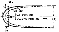
Подпись: -Vo LIVE GRAPH

Подпись: Fig.2.1 Shapes and pressure distributions of bodies produced by a single two-dimensional source line (dashed lines) and by a single threedimensional source (full lines).

Click here to view

and generates a streamsurface dividing the air emerging from the source from the mainstream air. This streamsurface may be regarded as the surface of a blunt solid body. The source material is all turned back and fills an area

far downstream with the velocity Vq, so that

Q – |d2Vq (2.15)

in threedimensional flows; and

Q = t V0 (2.16)

Подпись:in twodimensional flows; where Q is, respectively, the volume of air that emerges from the point source in unit time, or the volume in unit time that emerges from unit (lateral) length of the line source. The velocity field induced by a source alone can readily be determined: for reasons of symmetry, the velocity v is directed along the radius vector _r from the source and it is the same at all points on a sphere – or a circle – with the source

Подпись: (2.19)Подпись:_1 IT 16 2

in threedimensional flows: and

Ir__Lt

V0 " 2" 7

in twodimensional flows. These relations and the example in Fig.2.1 show that the perturbation velocities are much lower in threedimensional flows than in twodimensional flows.

Consider now a non-lifting, symmetrical, aerofoil in an inviscid incompress­ible flow. Such an unswept wing can be represented by a distribution of straight source filaments q(x)dx along the chord c. We now make use of the fact that individual solutions for isolated singularities, which auto­matically fulfil the equation of motion, can be superposed. For a distribution of infinitely long source lines, we find for the velocity component vz normal to the mainstream

Подпись:v (x,0)

—– = ± і q(x)

which expresses the plausible fact that, at any point, half the source mater­ial is squeezed out upwards and the other half downwards. (2.21) is used as a first approximation for vz on the surface of thin aerofoils, within the context of linearised theory. v? can be related to the shape of the aerofoil if the boundary condition (2.7) is linearised to

dz(x) _

vz(x)

(2.22)

dx

о

i. e. if we assume vx(x, z)

« Vq, as in

(2.9). Hence,

q(x) =

“oTT1 •

(2.23)

By integration,

z(x) =

2^0/X<l(X,)

dx’

(2.24)

and, in particular,

. 1

z(0) = z(c) =

Що’ q(x,)

d(x’/c) = 0

»

i. e. the overall strengths of the sources and sinks must be equal in order to obtain a practical aerofoil section which forms a closed contour.

Подпись:Подпись: 1 f q(xt) d(*'/c) 2irVo J 41 ' x/c “ x'/c

THE TREATMENT OF AIRFLOWS

With the source distribution being known, the streamwise velocity increment vx can be determined. A single source filament produces on the chordline

These very simple examples will have demonstrated the very many steps we are prepared to take in order to get near a solution. In view of this, it is again and again a matter of wondrous surprise when we find that the answers we obtain in this way bear such a close resemblance to what we observe and that our thinking was not misguided, after all. It may also be said that the linearisation procedure with its underlying concept of small perturbations has made it easier in many ways to think about these flows.

There remains the question of how to obtain actual numerical answers, even in simple cases like (2.25) where only an integration is involved. To explain numerical methods in detail goes beyond the scope of this book, and so we refer only to some of the many valuable accounts of these matters, which have been given recently, such as those by J J Smolderen (1972), P J Roache (1972),

D Rues (1973), E Krause (1973) and (1975), R C Lock (1975) , and M G Hall (1975).

2.3 Some models to describe the compressibility of the air. We may now follow up a little further some of the concepts and approximations we use when dealing with compressible flows. Consider inviscid subsonic flows so that

(2.2) applies.

A very simple method is that of E G Broadbent (1965) who treated a two­dimensional flow (originally, the flow past an electric arc transverse to an airstream), where the assumption could be made that pressure changes may be ignored as compared with density changes and that the streamline pattern is not affected by the Mach number. The equation of motion can then be simpli­fied (case 2 on page 27) and solved to give

V = —L. f (2.27)

which relates the velocity V in compressible flow to the velocity in in­compressible flow. Only the density ratio remains to be determined. A Betz & E Krahn (1949) have derived this relation also for twodimensional flows past solid bodies and found it a useful approximation in the case of a circular cylinder. No method of this kind has been developed for threedimensional flows and we are, therefore, again reduced to methods which are based on the assump­tion that perturbations are small. But these methods have the practical advantage of leading to universal compressibility factors.

Подпись: where THE TREATMENT OF AIRFLOWS
THE TREATMENT OF AIRFLOWS

For small perturbations, all the mixed terms in (2.2) can be ignored, and only the term (Эф/Эх)2/а2 must be taken into account in the first three terms since it cannot be regarded as small as compared with unity for the high – subsonic flows to be considered. (2.2) then reduces to

for subcritical flows. If we now make yet another drastic assumption and con­sider the value of 8 to be constant, then (2.28) can be reduced to the potential equation for an incompressible flow by the application of the Prandtl-Glauert procedure (see H Glauert (1928), L Prandtl (1936)). For the threedimensional flow past a wing of aspect ratio A = 4s^/S, swept through an angle we transform the wing into an analogous wing (suffix a) by means of

xa =

X

У a =

By

za _

Bz

Подпись: (2.30)

The streamline analogy of A Busemann (1928) and В GBthert (1941) is applied to wings as explained by D KUchemann & J Weber (1953). The two perturbation potentials are then such that both the real wing and the analogous wing are s treamsurfaces. Thus,

2 2 2

д ф Эф Эф

– 0 , (2.31)

Эх Эу 3z

a J a. a

as required, for an analogous wing which is thinner than the given wing,

THE TREATMENT OF AIRFLOWSt

Подпись:a

c

and which is more highly swept:

tan фа = і tancp.

Since the lateral dimensions have been reduced according to (2.30), ratio of the analogous wing is also reduced:

Aa = 6 A. (2.34)

THE TREATMENT OF AIRFLOWS Подпись: 1 .2 vxa Подпись: (2.35)

From the solution ф of (2.31), the perturbations velocity components v and Vy3 can be derived and these are then related to those of the real wing £y

and

(2.36)

It remains to find a suitable constant value for the parameter 6. The simpl­est approximation is to replace V in (2.29) by the mainstream velocity Vq and the velocity of sound by its value a^ in the mainstream so that

* (2’37)

This is the original "Prandtl-Glauert factor". There have been many attempts to improve on this approximation, and one that has been successful and simple has been proposed by J Weber (1948). This is to replace V in (2.29) by its local value in incompressible flow and again a by ад, so that

This takes at least some account of the fact that the local velocity over the aerofoil is different from the mainstream velocity. In a general way, this approximation is now known as the method of local linearisation, as described by J R Spreiter (1962). Weber’s rule usually gives a better representation of the actual values than the original Prandtl-Glauert rule. The main feature of this procedure is that it circumvents the real problem and reduces the calculation of a compressible flow to that of an incompressible flow. Its implications for swept wings will be discussed further in Section 4.2.

This concept of compressibility factors has proved so powerful that we tend to think in these terms as though they expressed some physical property of these flows. Thus, rather too easily, we tend to regard pressure distributions in compressible flow as scaled-up or stretched versions of those in incompress­ible flow. It is only recently that a practical method for obtaining exact

numerical solutions for twodimensional compressible flows around aerofoils has been developed by С C L Sells (1967). This allows us to determine the error introduced by the approximations, but isolated numerical answers cannot affect our way of thinking about the physics of the flow very much. However, Sells’s pioneer method has proved to be extremely useful and has been the basis of several extensions which facilitate the numerical work, by С M Albone (1971) and by P R Garabedian & D G Korn (1971). It has also been successfully extended to deal with supercritical flows, as will be discussed in Section 4.8. Sells uses conformal mapping – which has to be done numerically – of the region exterior to the aerofoil in the physical plane onto the interior of the unit circle in the working plane. In this way, the unbounded region of the physical flow is transformed into a finite closed region suitable for numeri­cal work. How very well the results of Sells’s method agree with experimental results may be seen from an example given by R C Lock (1975) for the NACA 0012 aerofoil section with t/c = 0.12 at a = 0 and Mo = 0.74. Another comparison between Sells’s results and various approximations for a lifting elliptical aerofoil has shown that the simple Prandtl-Glauert rule is quite inadequate, and also that a consistent method by W Gretler (1965), which includes all second-order terms, is still not good enough. Evidently, higher-order terms play a significant part. On the other hand, empirical compressibility correc­tions derived by P G Wilby (1967) and by R C Lock et at. (1968) and also the Weber rule may give good answers. We shall have to fall back on such empirical factors when we discuss threedimensional wings in Section 4.4.

All these remarks apply only to a particular kind of compressible flow. Math­ematically, the term Vx/a in (2.6) must be smaller than unity, and the equa­tion is then of the elliptic type. As soon as Vx/a exceeds unity in a two­dimensional flow, the equation changes type and becomes hyperbolic. The main­stream Mach number at which this changeover occurs is called the critical Mach number. Slower flows are called subcritical and faster flows supercritical, and we speak of transonic or mixed flows when the flowfield contains several regions in which different types of equation apply. These distinctions go to­gether with fundamental physical changes. These and the definition of critical conditions will be discussed in more detail in Sections 4.2 and 6.3.

The physical changes can readily be seen in the simple case of the inviscid flow through a straight tube or pipe, which is onedimensional. The subcritical or subsonic flow is trivial: just a parallel flow with all flow parameters con­stant across and along the tube. But when the upstream velocity is greater than the velocity of sound – when it is supersonic – two states are possible: the flow may continue uniformly at the same speed, or it may go through a shock­wave and become subsonic downstream of it. In going through the shockwave, density and pressure are increased, but the velocity is reduced. Mathematically, a shockwave is a discontinuity but, physically, viscosity and heat conduction must have a dissipative effect and make the changes gradual. It turns out, however, that the extent of this region is of the order of the mean free path of the gas molecules and thus the concept of a discontinuous change is an admiss­ible approximation when the gas can be regarded as a continuum. The compres­sion through a shockwave is associated with energy losses*) and the entropy of

■’Strictly, no energy is ever lost. Whenever we loosely use this term, we mean that the available energy is reduced by transfer into other forms of energy, such as heat, which cannot be utilised by the system under consideration for the purpose we have in mind. See also Section 3.6.

the gas increases. Therefore, the reverse motion – an expansion or rarefac­tion shock – is not physically possible, because the entropy change through it would be a decrease. Thus expansions in supersonic flows are gradual.

Since we are interested in the aerodynamic design of aircraft, we note here that shockwaves and expansions in supersonic flows may be useful flow elements whenever we want to generate pressures over a body, which are either higher or lower than the mainstream pressure. Specifically, when we want to generate lift forces through a compression of the air underneath a body, then one or several shockwaves will serve that purpose. But we shall have to pay for it because of the energy losses involved, i. e. the energy available to do useful work is reduced. Lift generated in this way will be accompanied by a drag force, a wavedrag.

When the mainstream is supersonic, the concept of small perturbations may again be used in some cases to derive a powerful linearised theory for super­sonic flows – a counterpart to that described for subsonic flows in Section

2.2. Practical applications of this theory, which help us to order our thoughts, will be described in the appropriate places below. The method of singularities can also be extended to supersonic flows (see the textbooks listed above; also E Leiter (1975)).

2.4 Viscous interactions – flow separations. We have already mentioned the concept of the boundary layer which forms along solid surfaces and which allows the flowfield to be subdivided into an outer region, where the flow is regarded as inviscid, and an inner region, where it is essentially viscous.

The flow within the boundary layer may be laminar or turbulent or in a trans­itional state in between. The boundary layer grows as it flows along and we have already seen that this produces a displacement effect on the outer stream. Thus the pressure distribution over a body results from the combined effects of the inner and outer solutions, and the overall flow can only exist if both the inner and outer flows are physically possible and compatible so that their interactions are such that they can be matched. This concept of matched flows is of great practical importance, and we shall find that there are cases where the flow in the boundary layer, say, develops in such a way that the particu­lar type of flow reaches a state where it can no longer exist and where it must change. It may then happen that the whole flow pattern must change with it into another overall pattern. This aspect of viscous interactions must be given the closest attention in the design problem: we always design aircraft to have a certain type of flow, and it is of vital importance that we know when this flow ceases to exist, that is, what the conditions are which deter­mine the physical limits of its existence. In most cases, such a departure from the design flow has undesirable consequences, especially when the resul­ting new type of flow is unsteady. What one would really like is to design the aircraft in such a way that it returns by itself, without oscillations, to the design type of flow after an inadvertent excursion beyond its boundary.

But there are also cases where an aircraft may be required to fly safely beyond these limits.

Viscous interactions are the most frequent causes of such flow breakdowns, and that is one reason why a thorough knowledge of the development of the boundary layer is so important in practical applications. On a lifting wing, the boun­dary layer is, in general, subjected to an external flow with pressure changes which are large, especially at subsonic and transonic speeds, where most of the lift is generated by suction forces, that is, pressures below that of the main­stream. As we shall see in more detail later, this suction should be as high as possible and act over as large a part of the upper surface as possible.

This implies that, downstream of the suction region, the pressure must rise as steeply as possible so as to come back to some value near that of the main­stream at the trailing edge of the wing. The boundary layer can, therefore, be regarded as another design mechanism which produces or sustains compressions in the flow, or pressure recoveries. To be of practical use, it must be pos­sible to fit the boundary layer between an external compressive flow and a solid wall, and it must remain attached to the wall throughout this adverse pressure gradient. Again, we must pay for this because there are energy losses involved, in the form of a reduction in the momentum of the boundary layer and in the total head, and because the boundary layer forms a wake as it leaves the wing. Thus lift generated in this way will again be accompanied by a drag force, a viscous drag, part of which will be manifested as skin – friction forces along the surface and another part as pressure forces.

Apart from boundary-layer flows in adverse pressure gradients, we need to know many other properties, such as how and where transition from the laminar to the turbulent state occurs. Transition is one of the fundamental phenomena in fluid mechanics, which has received much attention from the earliest days but has so far defied our understanding in many of its aspects (see e. g.

L F Crabtree (1958), I Tani (1969), M V Morkovin (1969), M G Hall (1971),

E H Hirschel (1973), E Reshotko (1975). In aircraft design, all this needs to be worked out for threedimensional flows about rather complex shapes, not just for the twodimensional flow along a flat plate.

Perhaps the most important boundary-layer phenomenon is flow separation. Its treatment presents formidable difficulties, conceptually, experimentally, and theoretically. It is fairly easy to see why flow separation may occur in a boundary layer when it is subjected to an adverse pressure gradient, if boundary-layer concepts hold. Then the slower particles within the boundary layer have to flow against the same pressure rise as the faster particles in the outer stream. Both will be retarded but the particles within the boundary layer more so, because their kinetic energy is less, especially for those par­ticles nearer the wall where skin friction holds them back. The velocity pro­files through the boundary layer will then deform in the manner indicated in Fig. 2.2, which represents Prandtl’s classical model of flow separation: the flow lifts off the wall at a separation point where the skin friction becomes zero and the air flows backwards behind it.

This classical flow model has been the basis of numerous investigations, and many criteria have been put forward to predict the onset of separation and to describe the behaviour near the separation point. We mention here the crite­rion of В S Stratford (1959), which formulates the observation that turbulent boundary layers can withstand a larger pressure rise than laminar layers. How­ever, the usefulness of Prandtl’s flow model is limited if we want to know what happens on aircraft. The model refers to a hypothetical twodimensional steady flow and it does not tell us what the consequences of the flow separa­tion are (Prandtl recognised this and put forward some possible flow patterns which we shall discuss later). What we have already mentioned could very well happen, namely, that the interaction between the inner and outer flows is such that the overall flow patterns will break down and must change. In that case, the whole pressure field may also change significantly and the condition which led to separation at that particular point may no longer apply. The resulting flowfield may differ substantially from the one we started from, and separa­tion may be located at a different point.

Consider, for example, the simple case where the outer flow was initially strictly twodimensional and steady. If flow separation occurs, we have no reason to suppose that the resulting flow should also he twodimensional and steady. We have no means of telling why it should not acquire, say, some span – wise periodicity across the stream, or why it should not be time-dependent, with the separation point oscillating to and fro. Even if the flow with separa­tion did remain twodimensional and steady, the separation point need not be at the position calculated by boundary-layer theory for the pressure distribution of the initial flow without separation. It is vital to know about these matters in aircraft design and to be able to predict them and, if necessary, to avoid them. And all this must be clarified, of course, for the real three­dimensional flow. Here lie the real difficulties, and much remains to be done
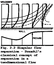
Подпись: VELOCITY Fig. 2.2 Singular flow separation - Prandtl's classical concept of separation in a twodimensional flow THE TREATMENT OF AIRFLOWS

Before we proceed to discuss what little we know about these matters, we re­mind ourselves that the classical model of flow separation, based on the boun­dary-layer concept and viscous shear forces, is not the only mechanism that can lead to separation in twodimensional flows. Another possible mechanism is illustrated in Fig. 2.3. This type of flow occurs typically near the sharp

trailing edge of an aerofoil and is, therefore, of practical importance. The two boundary layers from the upper and lower surfaces meet and form a wake, and the confluence is characterised by curved streamlines, so that vorticity generated further upstream in the two viscous layers is transported along curved paths. This induces a velocity field (which is usually ignored in boun­dary-layer theory because one thinks primarily in terms of a flow along a flat wall where these induced velocities are zero, to a first order); it can readily be seen that these induced velocities will have a component which is directed against the flow and will retard it. If the vorticity is strong enough
and if the curvature is large enough, this retardation may bring the flow near the wall to a halt and make it separate. This flow model has been proposed by D Kllchemann (1967) and investigated by P D Smith (1970). J E Green (1972) has discussed some of the implications of this separation mechanism. Fig. 2.3 shows two such flows, one with smooth outflow and one with separation, caused in this case entirely by vorticity-induced velocities and not by viscous forces. In fact, the results have been calculated by P D Smith for an inviscid but rotational flow in a layer near the surface and in the wake.

This concept of an inviscid shear flow can be quite useful in some cases.

Flow separation in three dimensions is closely associated with the fact that streamlines near a solid surface are, in general, not parallel to the surface. The concept of crossflows is introduced to indicate that there are velocity components inside the boundary layer, which are normal to the velocity vector just outside the boundary layer, when the outer flow is threedimensional with curved streamlines. Further, the concept of limiting streamlines in the sur­face is introduced to indicate the direction of the streamlines as z 0 , when the streamlines become otherwise parallel to the surface. Limiting streamlines lie closely along skin-friction lines. But streamlines can also greatly increase, or decrease, their distance from the surface in the neigh­bourhood of certain lines. These are the ordinary separation lines (as opposed to the singular separation line in Fig. 2.2), where the flow lifts off the surface and where a surface of separation is formed. Ordinary separation lines are very important in practice, as are their opposite counterparts, the ordinary attachment lines, which may be regarded as a physical generalisation of what is usually called a stagnation point in twodimensional flows.

Threedimensional flow separations have been recognised as an important pheno­menon only fairly recently. We refer to fundamental papers by E C Maskell

(1955) , E A Eichelbrenner & A Oudart (1955), R Legendre (1956), and M J Lighthill (1963), where the main topological features of flow separation in three dimensions are described. More recently, J H В Smith (1975) and D J Peake & W J Rainbird (1976) have given extensive reviews of separation in steady threedimensional flows. We illustrate the main concepts by a few examples.

Fig.2.4 shows the typical herringbone pattern of the limiting streamlines in the surface near an ordinary attachment line (A). This could be the frontview

THE TREATMENT OF AIRFLOWS

Frontvicw Sideview

Fig. 2.4 Attachment flows

of the flow over a rounded swept leading edge, but patterns like this must occur in the flow past all threedimensional bodies of general shape. In the sideview, an attachment flow may look like the familiar twodimensional flow near a stagnation point, but this should be regarded as a singular case. Part of the curved flow is within the viscous region (between the dashed line and the body in Fig. 2.4), and the state of the boundary layer may already be determined here. A laminar boundary layer beneath such an external flow may be unstable to small disturbances and eventually become turbulent in the man­ner described by GHrtler (see e. g. P Colak-Antic (1971)). Alternatively, the flow along the attachment line may become turbulent by what is called contami­nation. In that case, there is also the possibility that the flow may revert to the laminar state because of the strong divergence in the flow, which may have a stabilising effect. These are important matters in aircraft design, but very little is as yet known about what happens in practical situations.

THE TREATMENT OF AIRFLOWS

Fig. 2.5 Planviews of two types of flow near a swept leading edge

Next, we consider the flow further away from an attachment line where the streamlines in the outer flow are, in general, curved. Fig. 2.5 shows typical examples which may be interpreted as planviews of flows downstream of a swept leading edge. In these curved flows, the particles are subjected also to cen­trifugal forces, but the pressure may still be assumed to be roughly the same throughout the boundary layer. It then follows that slower particles nearer to the wall must follow a more highly-curved path (dashed lines in Fig. 2.5) than faster particles further out (full lines), to maintain equilibrium. This characteristic feature has important consequences. One is that these effects of curvature may lead to yet another mechanism to make laminar boundary lay­ers turbulent, in addition to that usually described as Tollmien-Schlichting instability. This is the Owen or sweep instability, which may imply that the laminar run in the threedimensional flow over swept wings may be shorter than that on a corresponding unswept wing where the flow is more twodimensional in character. Another consequence of the curvature may be the occurrence of a flow separation. According to E C Maskell & J Weber (1959), four different cases may be distinguished as far as the pressure field in such a flow is con­cerned, from one which makes flow separations impossible to another which is wholly favourable to the occurrence of flow separations. The latter is the one where the pressure rises rearwards as well as inwards, and this is the one that normally occurs behind the suction peak (marked Cp min in Fig. 2.5) on a sheared wing. Along the line of the suction peak, the curvature of the streamlines in the outer flow changes sign, and the streamlines curve outwards downstream of the peak. Streamlines within the boundary layer follow this pattern but, as explained above, the curvature must be higher. In the case shown on the lefthand side of Fig. 2.5, the curvatures are small enough for the flow through the whole boundary layer to continue regularly but, in the case on the righthand side, the limiting streamlines in the surface are suf­ficiently curved to point eventually in the same direction and to run tangen­tially into a single line and to have a cusp on that line, as Maskell des­cribed it. This then is an ordinary separation line, as defined above. It can clearly be observed experimentally in oilflow patterns on the surface. A streamsurface of separation originates from that line. What matters is that the air near the surface of the body does not flow past the separation line and that we must find out, in any given case, the shape of the separation surface and the nature of the flow beyond it.

We can make a fundamental distinction between flows where the part of the body surface beyond the separation streamsurface is wetted by mainstream air and flows where it is not. These two typical cases of separation from a general curved surface are illustrated in Figs. 2.6 and 2.7, where the possible extent of the viscous region is also indicated; the flow external to this region may be considered as predominantly inviscid. Fig. 2.6 represents the case where a bubble is formed, whereas Fig. 2.7 represents the formation of a

SURFACE OF

THE TREATMENT OF AIRFLOWS

Fig. 2.6 Separation in a threedimensional flow, leading to a bubble with a singular separation point S

THE TREATMENT OF AIRFLOWS

Fig. 2.7 Ordinary separation in a threedimensional flow, leading to a vortex sheet

free shear layer acvortex sheet. In the first case, the surface of separation encloses fluid which is not part of the mainstream but is carried along with the body; in the second case, the space outside the body on either side of the surface of separation is filled wholly by mainstream fluid. The limiting streamlines in the surface are indicated and also how they join the separation line, in a reversed herringbone pattern, and then form the surface of separa­tion. The bubble formation requires the existence of one singular point S (a saddle point), where the behaviour of the flow is similar to that near a separation point in twodimensional flow. All other points along the lines of separation in Figs. 2.6 and 2.7 are ordinary separation points, as defined by Maskell. These examples explain why concepts based on twodimensional flows, where separation lines must be normal to the mainstream and composed of singular points, are of little use in the discussion of flow separation in three dimensions.

The examples in Figs. 2.6 and 2.7 also serve to show that, while the concepts of boundary-layer theory may be applicable upstream of and away from the sepa­ration line on the body, they are clearly not adequate in the neighbourhood of the separation line. The viscous region around the surface of separation does not necessarily possess the properties of a boundary layer either. The shear layer in Fig. 2.7 may be thought of as a surface of discontinuity, or thin vortex sheet, in its effects on the mainstream, if the Reynolds number is high enough. In the case of Fig. 2.6, slow viscous eddies will rotate inside the closed bubble and form an essential part of the flow. In practice, a combination of the two types of flow with a bubble and with a free shear layer may also occur. Maskell showed how each type of flow is characterised by a particular form of surface flow pattern and demonstrated how this approach can greatly simplify the construction of threedimensional skeletons of complex flow patterns. It is essential to clarify these in any given cases all too often, threedimensional flow patterns are misinterpreted.

Some examples of practical importance are sketched in Fig. 2.8 in a simplified form as the traces of the separation surfaces in a plane normal to a leading

THE TREATMENT OF AIRFLOWS

a Low sweep b Moderate sweep C High sweep

Fig. 2.8 Various possible shapes of threedimensional separation surfaces

edge near which separation is assumed to occur along a line marked Sj. The angle of sweep of the edge is varied. At zero or small angles of sweep, Fig. 2.8a, the flow may be nearly twodimensional and a closed bubble may be formed, i. e. the surface of separation reattaches to the body surface and contains a slowly rotating flow which is not part of the mainstream air. Such a flow is not strictly steady, but the concept of time-average streamlines is still useful. At the other extreme of high angles of sweep, Fig. 2.8 c, the flow is essentially threedimensional; the separation streamsurfaces are all open and the whole space is filled by mainstream air. This type of flow is usually quite steady. The separation surfaces may be interpreted as vortex sheets which roll up along their free edges into coiled vortex cores. These cores grow in space, as further vorticity is fed into them. There is usually another attachment surface, intersecting the body at Aj, which divides the air that is drawn into the vortex core from that which passes it by. In general, a secondary separation line S2 and a secondary vortex sheet are formed, because the air near the surface of the body is not able to run up against the adverse pressure gradient which must exist once the air has passed underneath the main vortex core, which induces a suction peak on the surface.

In principle, the process whereby further separation lines and vortex sheets are introduced may be continued indefinitely but, in real flows at finite Reynolds numbers, this process is terminated when the boundary layers and vortex sheets are no longer thin and when the little sheets are swallowed up by the viscous fluid surrounding them. Between the two extreme cases, there may be an intermediate type of flow at moderate angles of sweep, Fig. 2.8 b, which involves a bubble with at least two eddies of opposite sense inside it as well as a free surface of separation with a rolled-up core.

Closed bubbles with reattachment and coiled vortex sheets are concepts which play a very important part in aircraft design, and we must now look at some of these flew elements in more detail. Consider first flow elements which in­volve mainly bubble separations, as they have been described by L F Crabtree

(1957) and I Tani (1964). The front part of the surface of a bubble can usually be regarded as a thin curved shear layer, along which the pressure is nearly constant and below that of the mainstream. There is little flow inside this part of the bubble. To bend the shear layer back towards the surface of the body and to make it reattach requires a pressure rise, and this must be matched by a pressure rise in the outer flow. In the bubble, the pressure rise must be supplied by a viscous process: we say that the air in and near

the shear layer undergoes a process usually described as turbulent mixing.

This can indeed produce a rise in pressure along time-average streamlines and also in the outer flow where the streamlines lose some curvature as a result of a considerable thickening of the viscous region. For this to occur, the shear layer itself must first be turbulent. This leads to an essential dis­tinction between two different types of flow in those cases where the shear layer is the result of the separation of a laminar boundary layer and where it is laminar itself to begin with. Transition to the turbulent state must then occur in the shear layer on top of the bubble before the layer can re­attach to the surface through the mechanism of turbulent mixing. How and where this happens affects the size of the bubble: depending on whether transition occurs after a short run or a long run, the bubble is either short or long, compared with the dimensions of the body. P R Owen & L Klanfer (1953) have derived a criterion to distinguish between the two ‘types of bubble. In general aircraft applications, the short bubble is a useful flow element, the long bubble is not.

THE TREATMENT OF AIRFLOWS

The turbulent reattachment usually takes a relatively short length of the order of ten bubble heights or less downstream of transition. We can visualise

Fig. 2.9 Flows with turbulent reattachment

this part of the flow in terms of the sketch, Fig. 2.9 a. This is closely related to the flow with a pressure rise in a pipe or duct with a sudden enlargement of the cross-section, as sketched in Fig.2.9 b. There is again a bubble separation with reattachment, and the stream is assumed to be uniform far upstream (suffix 1) and again far downstream (suffix 2) if complete mix­ing has taken place. In this case, a pressure-rise coefficient can be deter­mined by application of the momentum theorem. Expressed in a canonical form in terms of the initial dynamic head JpV-^2г this gives

Подпись: a =Подпись: >THE TREATMENT OF AIRFLOWS(2.39)

where V are velocities and A cross-sectional areas. It is assumed here that the pressure over the rearward-facing base is constant and equal to p^. This very simple flow model, which can easily be realised in practice, tells
us that the pressure rise which can be obtained by a mixing process is limited. The value of a according to (2.39) has a maximum which is 1/2.

The flow at the rear end of a closed bubble differs from pipe flow in that there is only one wall so that some air may flow into (or out of) a cylindri­cal surface of integration (dashed line in Fig. 2.9 a). Momentum can then be added during the mixing process and transferred into an additional pressure rise, so that the pressure-rise coefficient, though still limited, has a max­imum value which can be greater than 1/2. This momentum transfer through entrainment could thus allow a greater pressure rise to be sustained, but the actual amount will depend on how this mixing flow can be matched to the exter­nal stream. The existence of a maximum pressure recovery seems to imply that there is also a maximum possible shear stress in the turbulent entrainment. A somewhat different, but basically similar, pressure recovery coefficient has been used by A Roshko & J C Lau (1965) in their investigation of the reattach­ment of free shear layers.

This type of flow, which relies so much on vigorous turbulent mixing, is ne­cessarily associated with energy losses which are likely to be greater than those associated with turbulent boundary layers. Even so, it is used in air­craft design (mainly in the form of short bubbles) simply because it offers another viscous flow element which can be matched to an external flow with pressure rise, under certain conditions. There are so few of these! But the existence of a maximum pressure rise implies that a matched flow may break доит altogether when subjected to even relatively small changes. Long bubbles on aerofoils can adjust themselves fairly readily by getting longer until their tailend sticks into a region in the external flow where the required pressure rise is smaller and does not exceed the limiting value. If need be, long bubbles extend beyond the trailing edge into the wake. Short bubbles cannot do this: they burst. The maximum value of the pressure-rise coeffi­cient a has been found to be about 0.35 in incompressible flows about aerofoils; when the external flow demands more than this, the bubble bursts and the whole flow pattern breaks down and changes radically. It then includes a large-scale flow separation, whereas before it may have given the appearance of an attached flow, because short bubbles are normally so very small, compared with the dimensions of the aerofoil (see also Section 4.7,

Fig. 4.40). Another criterion for bubble bursting has been given more recently by F X Wortmann (1974).

Подпись: Fig. 2.10 Rear end of a bubble with shockwave

At low speeds, the external compressions are necessarily gradual, but discon­tinuous compressions in the form of shockwaves may occur in transonic and in supersonic streams. In aircraft design, especially for transonic speeds, one likes the shockwaves to be rather strong, as we shall see in Section 4.8. We are then faced with the problem of finding a viscous flow element which can be fitted between the foot of the shockwave and the solid wall. A short bub­ble can serve this purpose, and so the combination of a shockwave and a turb-

Fig. 2.11 Shock-induced bubble separation

Подпись: a Подпись: 4 Y + 1 Подпись: (2.40)

ulent mixing region is of practical interest. A simple combination of these flow elements is sketched in Fig. 2.10, which can be interpreted as the re­attaching flow at the end of a bubble underneath an external flow which goes from a supersonic speed to a subsonic speed through a shockwave. To a first approximation within the concept of boundary layers, the pressure rise through the unswept normal shockwave and that through the mixing region must be the same and hence

THE TREATMENT OF AIRFLOWS Подпись: 1 Подпись: _1 Y + 1 -*—— a Подпись: 1 1 - 0.6a Подпись: (2.41)

Thus the upstream Mach number Mj is limited by the pressure rise that can be provided by the mixing process, so that

for air. We have = 1.2 for a = 1/2, but Mj could be greater than 1.2 if momentum transfer by entrainment could increase the value of a . This would be very welcome in aircraft design but we do not yet know how to bring this about.

The sketch in Fig. 2.11 illustrates a more complete flow pattern, showing the whole bubble separation with reattachment underneath a normal shockwave which may be thought of as terminating a local supersonic region over an aerofoil. This simplified flow model is based on observations made by J Seddon (1960) .

It incorporates a distinctive forward leg at the foot of the shockwave so that in some region above the bubble, there are two compression processes in series one through this forward oblique shock, matched by a pressure rise in the separating boundary layer underneath, and another through the rearward leg of the shock, matched by the pressure rise from turbulent mixing during the re­attachment process. In Seddon’s experiment, = 1.5 could be realised.

The forward leg reduced the local Mach number to about 1.2 and the rearward leg together with turbulent mixing reduced the Mach number further from 1.2 to a subsonic value. So we arrive at a flow model which is at least reason­ably consistent. But the difficulties which are involved in developing this into a method suitable for practical design purposes have not yet been over­come. These are formidable, both theoretically and experimentally, because both the outer inviscid flow and the inner viscous flow are very complex.

Подпись: Fig. 2.12 Shock-induced separation with vortex sheet Подпись: Fig. 2.13 Local supersonic region on top of vortex sheet

Consider now flow elements which involve mainly vortex-sheet separations (see e. g. D Klichemann & J Weber (1965), J H В Smith (1975)). We note first that the concepts discussed so far result mainly from thinking about essentially

twodimensional flows. However, it is doubtful how far they apply to the three­dimensional flows, like those over swept wings, which are of real practical interest. There is no doubt that Fig. 2.11 does not apply when the shock is highly swept in planview. In that case, we may still expect that a flow separation occurs at the foot of the shockwave, but the separation surface can then take the form of a vortex sheet, as sketched in Fig. 2.12. The flow direction immediately behind the foot of the shockwave is then reversed and the air actually experiences a fall in pressure which is, nevertheless, compatible with a pressure rise through the shockwave in the external stream. These glancing interactions have been the object of some study (see e. g. A Stanbrook (1961)), but we know very little about their occurrence on swept wings where, again, they constitute a departure from twodimensional flow concepts.

Shockwaves and vortex sheets need not only occur in the combination shown in Fig. 2.12 but also in the form sketched in Fig. 2.13. Here, the vortex sheet may have been generated further upstream, perhaps under conditions where the flow was still subcritical, as in Fig. 2.8 c. At supercritical conditions, the flow may expand over the outside of the vortex sheet and a local super­sonic region may be formed there, terminated by a shockwave. Compared with the more familiar local supersonic region over the front of a twodimensional aerofoil section, the whole region is now lifted off the surface. Such flows can exist only in three dimensions and are, therefore, of particular interest for swept wings. A vortex core is then formed and must expand in the spanwise direction, if the flow is to be steady. A conical flow of this kind has been observed by D Pierce & D A Treadgold (1964), and there are indications that similar flows may exist on threedimensional swept wings. This applies when the angle of sweep of the separation line is high, but very little is known about what happens at moderate angles of sweep and about how wings could profitably be designed to have this type of flow. All these are typical examples which demonstrate clearly that we are concerned with matters where any progress made in research on fundamental flow mechanisms could be exploited immediately and profitably in practical applications.

In most of the flow elements considered so far, separation was assumed to occur somewhere along a smooth surface. There is no reason and no evidence to suppose that the resulting separated flow should always be steady. But flow steadiness is one of the essential requirements in aircraft design, and that is why we are vitally interested in fixing separation lines at some well – defined place and in keeping the separation lines firmly under control. So far, the only concept we can think about as one which will fix flow separation is the aerodynamicatly sharp edge. This may be defined as a geometric shape where the curvature is very high, or even infinite, so that the inviscid flow would acquire a very high, or even infinite, velocity and consequently a very high, or even infinite, adverse pressure gradient. This is meant to make the separation of a real viscous flow around this shape inevitable. We then say that the Kutta condition is fulfilled at such an edge and we mean by that that the outflow is smooth and that any infinite velocity or pressure gradient has been removed. This definition can also lead us to a useful approach to deal with the problem of fulfilling the Kutta condition. First, we think of the flow with a singularity at the edge, which an inviscid flow could make; second, we devise another flow which, when combined with the first, will remove the singularity. This approach has been used successfully by E C Maskell (1960) (see also D L I Kirkpatrick (1967)) in dealing with the flow separation from the leading edges of a slender wing, which will be discussed further in Sections 6.3 and 6.4.

We have already seen an example of a smooth outflow from an unswept sharp trailing edge in Fig.2.3(b), with separation confined to. the trailing edge only. In this simple case of a symmetrical body, an inviscid fluid can already flow smoothly from the trailing edge, and there is no particular difficulty in fitting a rotational or viscous flow into it, provided the flow reaches the trailing edge and does not already separate upstream of it. Matters are more complicated when the flow is not symmetrical on either side of the edge, as on an aerofoil put at an angle of incidence, and when two flows of different directions and/or speeds meet at some edge. As Helmholtz has said in 1868,

"any geometrically sharp edge must tear apart the fluid which flows past it and produce a surface of discontinuity, even when the remaining fluid moves only at moderate speeds".

How this tearing-apart may happen and how the Kutta condition of smooth out­flow may be fulfilled is a very important matter, which has been discussed and clarified more recently by К W Mangier & J H В Smith (1970), R Legendre

(1972) , and E C Maskell (1972). We want to illustrate this flow by three examples in which inviscid flows with edge singularities are converted into flows with smooth outflow, and the singularities removed, in three entirely different ways. We may think about them by visualising first inviscid flows with infinite velocities at the edges of thin solid plates and then converting these into real flows by the sudden application of viscosity. (Alternatively, the real flows can be thought of as being brought about by a starting process during which the air or the body are suddenly set in motion). In all three cases, the resulting flows can again be regarded as inviscid – the part that viscosity plays is to establish them.

Fig. 2.14 shows on the lefthand side the initial flows to be considered:

(a) the steady twodimensional flow past a flat plate at a small angle of in­cidence to the mainstream; (b) the steady twodimensional flow past a flat plate at right angles to the mainstream or, alternatively, the steady flow in a crossflow plane through a threedimensional slender wing; and (c) the steady twodimensional flow along a flat plate which separates two streams of differ­ent velocities and different total heads. In all three cases, the air far downstream settles down to a uniform parallel flow as though nothing had hap­pened. The converted flows are shown on the righthand side of Fig. 2.14.

They are quite different. The possibility that bubble separations occur has been excluded and, in all three cases, the sudden application of viscosity is supposed to lead to the formation of a surface of discontinuity, or vortex sheet, which rolls up into at least one coiled vortex core along the free edge. As we shall see later, such a vortex core is a powerful mechanism for concen­trating energy, which in turn induces a strong velocity field. This may be regarded as the physical means whereby the flow near the edge is straightened out.

In case (a), a starting vortex is formed, which is then carried downstream with the flow while the strength of the connecting vortex sheet gets weaker and weaker and becomes zero when the starting vortex reaches infinity. Thus the resulting flow is steady again and very simple. It seems almost literally "straightforward" to fit a viscous region in the form of a thin boundary layer and a thin wake into it. (However, closer inspection reveals many complexities see e. g. S N Brown & К Stewartson (1970)). Apart from small-scale turbulent fluctuations in the boundary layer and wake, the flow can be expected to be steady on time-average.

In case (b), at least one pair of strong coiled vortex cores is needed to straighten out the flow at the two edges. If the flow is meant to be two-

THE TREATMENT OF AIRFLOWS

dimensional, it must become time-dependent, as the vortex cores grow as a con­sequence of a certain mass of air being fed into them; they will also be left behind in the flow. If the flow is meant to represent the crossflow over a threedimensional slender wing, then the two cores will grow in space over the wing to accommodate the air. The flow is then similar to that sketched in Fig. 2.8 c. Again, viscous regions can readily be fitted into this flow pattern in the form of thin boundary layers and thin shear layers, if the Reynolds number is high enough, without upsetting the general characteristics. The threedimensional flow can be expected to be steady.

In case (c), the resulting flow is again time-dependent, vortex cores being swept downstream. In the general case with different speeds and different total heads in the two streams, a steady smooth outflow as in case (a) cannot exist unless the two flows are perfectly matched, which, in real flows, must include conditions for the densities and temperatures. In one possible mechanism, we may expect that a core with concentrated vorticity could do the job initially (as in the second case), but that another core is needed as the first is floating downstream and then yet another and so on. Thus, in this case, a possibly periodic succession of vortex cores may be needed to keep the flow straight near the edge and to maintain the velocity difference further downstream. Since this type of flow may be interpreted as representing part
of a nozzle from which a jet emerges, and since the velocity difference is then essential in practice so that kinetic energy is left behind in the jet, the Kutta condition appears to imply that, in this particular type of flow, the flow in the boundary of the jet is essentially unsteady and involves an array of vortex cores. The disturbances caused in this way must be expected to generate noise in the outer flowfield (see S M Damns & D Ktlchemann (1972)).

We note that the three mechanisms which are used to satisfy the Kutta condi­tion differ remarkably from one another. The first case is easy and almost trivial; the second case can lead to a steady threedimensional flow, but powerful concentrations of vorticity are needed to ensure smooth outflow; and the third case can lead to a time-dependent flow with periodic genera­tion of concentrated vorticity.

In the last two cases, the formation of a surface of discontinuity in the form of a coherent vortex sheet as a result of flow separation is an essen­tial mechanism, and we shall see later that flows like that in the first case do occur on threedimensional wings where again a vortex is generated at the separation line along the trailing edge. Thus vortex sheets are an important concept in aircraft aerodynamics, and there are many cases where the model of a thin vortex sheet in an otherwise irrotational inviscid flow is admissible and useful. We may consider such flows as being composed of three distinct elements: A solid body, one or several vortex cores, and outer connecting

vortex sheets linking the two others. Continuous vortex sheets are at all times formed by the same fluid particles which carry their vorticity with them. Further, the static pressure must be the same on either side of the sheet because it cannot take any force. These properties lead to boundary conditions for calculations but, so far, only a few particular solutions are known (see e. g. A Betz (1932) and (1950), M Stern (1956), D Ktlchemann & J Weber

(1965) , J H В Smith (1966) , D W Moore & P G Saffman (1973), D W Moore (1974) and (1975)). These vortex motions will be discussed further in Section 6.3.

The main theorems concerning vortex motions were established by H von Helmholtz (1858) and (1868) and by Lord Kelvin (1869) . They can be found in any good textbook on fluid mechanics. In aircraft aerodynamics, we are concerned not only with free vortex sheets but also with bound vortex lines by which we represent solid surfaces. These are hypothetical to the extent that they are regarded as capable of sustaining a pressure, and as not moving with the fluid.

The velocity field of an element of vortex line is given by Biot-Savart’s equation. To represent a flow by the sum of the induced velocities of a number of such singularities automatically ensures that the equations of inviscid flow are satisfied. Thus distributions of sources and vortices can be used to represent a thick lifting wing with a vortex wake.

In Fig. 2.15 are sketched the conditions at a point P of a threedimensional vortex sheet, the tangent plane at P coinciding with the plane of the paper. V£ and Ve are the velocities on either side of the sheet. Vs = J (V£ + Ve) is the so-called mean velocity, and у is the vorticity vector which is per­pendicular to the velocities it induces on either side of the sheet. The general result for any vortex sheet is that the induced velocity increments are Ave = +y/2 and Avf = – y/2 and that у, Vi, and Ve are coplanar. у

has the dimension of a speed and represents the vortex strength per unit length of a vortex line.

If the suffixes і and e refer to the two sides of the sheet, Bernoulli’s

THE TREATMENT OF AIRFLOWS

Fig. 2.15 Conditions at a point in the tangent plane of a vortex sheet

equation for steady flows may be written

Hi = Pi + Jpv.2 ;

H = p e ^e

+ Jpve2

.

(2.42)

Thus the pressure difference,

Ap, across the sheet

is

Др = Pe

– p. = AH + Jp(V.2

/—N

CM

0)

1

9

(2.43)

AH = He – being the difference in total pressure. Elementary trigono­metry, applied to Fig. 2.15, puts (2.43) in the form

Ap = AH – pVgY віпф. (2.44)

This equation has obvious importance in dynamical problems and some particu­lar cases are now taken.

1 For a vortex sheet separating regions of equal total pressure, for exam­ple, a trailing vortex sheet, both Ap and AH are zero, and so ф is zero also. The velocities on either side of the sheet are then equal in magnitude and equally inclined to the vorticity or mean velocity vectors which are in the same direction.

2 If AH is not zero, as for the surface of a bubble, then ф is also not zero if the vortex sheet is such that Ap is necessarily zero.

3 In the case of a bound vortex sheet, such as that which represents a so­lid boundary, Ap is not zero. If the total pressure is the same on both sides, as is usual with a thin wing,

Ap = pVssini|/ , (2.45)

and the solid boundary must sustain this pressure difference. As an example, consider a thin unswept wing of large span. Except near the ends, the vorti­city vector is almost at right angles to the mainstream; thus ф – тг/2. Further, V8 may be taken as Vo, the speed of the stream at infinity. Therefore,

Лр = PV0Y » (2.46)

which is commonly called the Kutta-Joukowski theorem for the lift force. It holds for the local force from the vortex element; it is equally true for a whole wing. We shall return to these matters later when we discuss wing flows in more detail.

With regard to flows about the cores of vortex sheets, it is useful to distin­guish between threedimensional cores, which grot) in space, and twodimensional cores, which grow in time, and also between single-branched cores along the edges of vortex sheets and double-branched cores which the outer vortex sheets enter on one side and leave on the other. The key feature of cores growing in space is the strong interaction between swirl and axial velocity components in that the swirling fluid drawn into the core escapes in an axial direction and may acquire a high velocity along the axis, several times that of the main­stream. Twodimensional cores, where such an escape is precluded, must grow sufficiently in time to accommodate all the fluid: there is no twodimensional steady vortex-sheet core. In this respect, the traditional concept of a "line vortex", with a steady twodimensional flow like a potential vortex out­side and a solid-body rotation inside, is quite wrong. There are no physical means for producing it in an airstream. The fact that we can construct math­ematically exact solutions of the Navier-Stokes equations does not necessarily imply that they are physically realistic. We note in passing that, apart from the unrealistic line vortex, there are some other solutions which we actually have but cannot find a practical application for, at least not on aircraft aerodynamics. These are the group of exact solutions of the time – dependent Navier-Stokes equations for twodimensional swirling flows by C W Oseen (1912), J F Burgers (1948), and N Rott (1958).

How regions with concentrated vorticity can be generated in a fluid of low viscosity has been suggested by A Betz (1950). In view of the large kinetic energy in these swirling flows, he concluded they can only come about by the rotting-up of vortex sheets which originate from separation lines along solid bodies in the way described above. This is certainly confirmed in all known cases in aircraft aerodynamics, aand this is why the tightly-rolled vortex cores are so important in practice.

THE TREATMENT OF AIRFLOWS

THE TREATMENT OF AIRFLOWS

Fig. 2.16 Vortex sheets from long flat plates at an angle of incidence

Single-branched cores are formed as a rule on either side of the vortex-sheet wakes behind lifting wings. Double branched cores are less common. As far as we can see now, there may be several mechanisms to bring them about. One of these has already been described in Fig. 2.14 c. Another is associated with the big-scale flow about a lifting body when attachment and separation lines intersect on the surface of the body from which the vortex sheets spring, as illustrated in the lower part of Fig. 2.16 from observations by R L Maltby. It may be caused by putting a long flat plate of small aspect ratio with sharp

THE TREATMENT OF AIRFLOWS

Fig. 2.17 Sketch of the shape of the vortex sheet behind a body moving uni­formly downwards in still air. After Pierce (1961)

side edges at a slight angle of yaw. Without yaw, the flow and the vortex system may be symmetrical, as in the upper part of Fig.2.16, with the attach­ment line running down the middle of the plate. With yaw, attachment is along a zigzag line which intersects first one edge, then the other, and so on, and this leads to the formation of a new core at every intersection. We note that the flow is not necessarily symmetrical even without yaw: the symmetry of a

body placed symmetrically in a stream does not ensure the symmetry of the vortex pattern; a periodicity in the vortex wake is always a possible alter­native.

Another mechanism is not necessarily associated with a big-scale flow but may be a property of the sheet itself together with possible fluctuations in the flow in the immediate neighbourhood of the separation line, even when the line itself is firmly fixed. A flow of this kind is illustrated in Fig. 2.17 from observations by D Pierce (1961). Evidently, a small-scale array of double – branched cores can be superposed upon a big-scale flow which itself can have a large core. We can even envisage a flow which incorporates both a periodic array of large double-branched cores and another periodic array of small and again double-branched cores along the sheet. All these can grow either in space or in time or in both. What is observed fairly often is uniform shed­ding of vorticity. This appears to lead either to cores growing approxi­mately conically in space or to cores growing approximately linearly in time.

2.5 Flows suitable for aircraft applications. We have recognised by now a number of basic types of flow and flow elements and can proceed to consider what properties they should have to make them suitable for engineering applications in aircraft design. As already explained in Section 1.4, such a selection of healthy engineering flows will then lead to certain classes of shape and, out of these, types of aircraft can be constructed. This line of approach – from flows to shape – is the key feature and probably the most important aspect of the design method adopted here. It is considered to be the main principle underlying rational aeronautical engineering. But this principle has also been questioned from time to time, and we must be aware of the temptation that lies in the apparent possibility of obtaining solutions out of the powerful tools that we now have, regardless of what the flows are like. It is also said some times that, given the large engine powers now available, one could make a barndoor fly. This is even true, up to a point, but it is not aeronautical engineering as we understand it here.

There are certain basic criteria which should be fulfilled for a flow to be considered suitable for engineering applications. In the first place, the flow should be steady and stable. This means that flows which fluctuate and oscillate with time are, in general, not suitable. Also, the flow should be well-defined and insensitive to disturbances which it will meet in flight through the atmosphere. Any perturbations should not upset the flow alto­gether. Instead, it should be stable enough to revert to its initial state. Next, the flow should be controllable. It should be possible to produce quite a range of forces and moments on a flying body over a range of flight conditions within which a certain type of flow can exist. Any changes in forces and moments should not be abrupt but gradual and smooth and uniquely deter­mined. The pilot should be able to perform readily all the manoeuvres which are required from the aircraft to fulfil its functions. Ideally, the type of flow should be the same throughout the whole flight envelope of the aircraft, but we shall allow certain exceptions to this rule, provided the changes from one type of flow to another are also gradual and smooth. Lastly, the flow should be efficient. This means that the generation of lifting and propulsive forces should not be accompanied by large energy wastage. The flows must all be such that work is done on the air by the flying body. The energy needed for this is carried along in the aircraft in the form of fuel, and what is wanted is that the available lift work is as large a portion of the heat con­tent of the fuel as possible. We shall discuss these matters in more detail in Chapter 3.

There are some general features which flows past aircraft must have, indepen­dent of what the particular type of aircraft is. Geometrically, the shape of any aircraft will have a certain streamwise extent, or chord, and a certain lateral extent, or span. This body will have a certain mass and volume and hence a thickness, which can be expected to be smaller than the chord and the span. Thus we consider rather flattish shapes. This body moves through the air, or the air moves past it, and, to counteract the gravitational force on its mass, the airflow must exert an equal and opposite force on the body to maintain level flight. This lift force appears primarily in the form of pres­sure forces distributed over the surface of the body. Clearly, a lift force is generated if the pressure over the lower surface is higher than the ambient pressure, or if the pressure over the upper surface is lower than the ambient pressure, or if there is a combination of both. This implies that we are always concerned with flows which divide along some attachment line along the front of the body and then experience different changes of condition, depend­ing on whether the particles flow below or above the body. Downstream of the attachment line, the two flows should remain attached to the surface of the body until they meet again at a separation line along the side or the rear of the body. This separation line should remain fixed in the same position under all flight conditions. In the general case, the flow conditions on either side of the separation line will be different. For example, the magnitudes and directions of the velocities may differ. This means that a surface of discon­tinuity, or vortex sheet, will be formed, as discussed above. Flows with thin trailing vortex sheets are eminently suitable for engineering applications and an essential feature of aircraft aerodynamics. Further, viscous regions should be thin, and so E C Maskell (1961) formulated the generalised design objective as the achievement of thin-wake flows.

These conditions mean that singular separations as in Fig. 2.2 are undesirable, especially when the resulting bubble is of the kind shown in Fig. 2.3(a) and occupies an appreciable region over the rear of the body. Also generally un­desirable are bubble and vortex-sheet separations if they occur on smooth sur­faces as in Figs. 2.6 and 2.7, so that the separation lines are not necessa­rily fixed. What is wanted are vortex-sheet separations from aerodynamically sharp edges, where the Kutta condition is fulfilled, as has been discussed in connection with the flows sketched in Fig. 2.14. We note in this context that this type of flow imposes a condition on the static pressure to be reached at the edge: it must be the same at either side of the sheet and also along the separation line; its value is usually not very different from that of the ambient pressure in the mainstream.

Other essential flow elements on lifting bodies are expansions and compressions. Under supersonic conditions, these may take the form of Prandtl-Meyer expan­sions around edges and of shockwaves. Compressive flows, in particular, must follow any expansions so that the pressure rises again from a value below that in the mainstream to the right value required along the separation line. It is one of the main problems in aircraft design to find shapes with pressure distributions in inviscid flows with just the right pressure gradients, into which viscous regions along the surface can be fitted without upsetting the overall flow pattern and without involving unacceptably large energy losses.

This is why turbulent boundary layers, which can sustain large compressions, and turbulent mixing regions, as in Figs. 2.9 and 2.11, are of such practical interest. To exploit the pressure rise associated with the reattachment pro­cess, it is even admissible to have a secondary separation with reattachment between the primary attachment and separation lines, provided the resulting bubble is short and small in extent compared with the dimensions of the body. Secondary vortex-sheet separations, as in Fig. 2.8(c), are also acceptable flow elements.

In the thin viscous regions, the displacement thickness should be thin so that the actual pressures over the body do not deviate too much from those in in­viscid flow and the pressure drag remains small. The momentum thickness of the boundary layer and of the wake should be thin so that the skin-frietion drag remains small.

Some requirements which concern the state of the boundary layer may be in con­flict with one another. With regard to overcoming pressure rises, we would like the boundary layer to be turbulent. With regard to keeping the skin-fric­tion drag low, we would like the boundary layer to be laminar. Under normal flight conditions, a laminar boundary layer would be thinner than a turbulent boundary layer and produce less skin-friction drag. It would also have a smaller heat transfer from the air to the surface of the body. This matters especially at supersonic and higher flight speeds, where such an energy trans­fer must be regarded as an unwanted loss, which introduces severe engineering problems in the construction of high-speed aircraft. Unfortunately, there are so many disturbances of various kinds in the flow past most aircraft that long runs of laminar boundary layers over an appreciable part of the surface of the aircraft are difficult to maintain. So far, only small aircraft, such as some gliders, have successfully been designed to exploit the properties of natur­ally laminar boundary layers. There is just a possibility that future high­speed aircraft, flying at high Mach numbers and altitudes, might again benefit from naturally laminar flows. The expected advantages are so great, especi­ally with a view to saving fuel in long-range transport aircraft, that they provided enough incentive to spend a great effort on solving problems of bound­ary-layer control, i. e. on finding artificial means for keeping the boundary layer laminar, for instance by sucking part of the boundary layer away into the surface (see e. g. 6 V Lachmann (1961)). Although some of these flow mechanisms have been put on a sound physical basis, they have not yet found lasting engineering applications.

There are many flow elements involving energy addition to an airstream which find practical applications in the generation of propulsive forces. One of these is that sketched in Fig. 2.14(c). We leave the discussion of others until we come to the actual applications in Chapters 3 and 8.

In all the subsequent and more detailed discussions, the emphasis will be put firmly on the physical characteristics of the flows we want to use in designs. This may seem antiquated and old-fashioned at a time when computational aero­dynamics is coming to the fore, and when there is a growing belief that, given big enough computers, all our problems can be solved numerically. The approach adopted here does not follow this trend: many approximate methods will be described simply because they bring out clearly the essentials of the behavi­our of the flows in crucial and critical regions, and because they give a sound basis for design. Computers, like windtunnels, are welcome and much- needed tools, but they do not make physical insight redundant.

The motivation of aviation

1.3 Developments in transport technology, and in aviation in particular, are motivated not only by engineering incentives but also by its social implications and rewards. Moreover, apart from what society may want from aviation, the size of the job before us and what it will cost brings up problems. Many of the developments in aviation will have to be supported by society as a whole. So we must have good reasons why such deve­lopments are desirable and should be supported and paid for by society. We must admit that the technical case is not enough: the fact that something is technically feasible does not necessarily mean that it should be done. We need a wider and more rational basis for future developments in aeronautics, as a background to the problem of designing aircraft. However, we are only at the beginning in this search for guidelines, and we cannot yet offer a com­plete and rational answer to the question of motivation.

We are now going through a phase where many advocate that we should be guided by oomneroidl considerations: the creation of wealth. To put it crudely, a simple continuous cycle is envisaged: it begins at the "market place" where

we sell our wares and make a profit and where, at the same time, the blind or manipulated "market forces" dictate what the next sales line should be. The profits are then used to carry out the necessary research into the technical aspects of this new line and to finance the development and production of the new article. Then we go back to the market place, and so on (see e. g. F E Jones (1969)). This may be an arguable approach just now, but we cannot assume that it can serve as a guide in the long term. Less short-sighted is the view that "economic life is movement". This has always been true and is likely to hold also in the future.

More recently, the effects of technology on our environment and, in particular, what is called pollution have received attention (see e. g. P A Libby (1973)). These are serious matters which can provide some of the guidelines we are seeking and can lead to design requirements and criteria. Some of these, such as noise, will be taken up below.

If we really want a rational basis for future long-term developments, we must be guided by what we know about the nature of mm. If we knew enough about the behaviour of man and his natural make-up and about people and their insti­tutions in relation to their environment, we might conceivably evolve a system of organising our living conditions, which is at least sufficient in that it is so designed that our inborn instincts and our natural make-up and our legitimate interests are respected or, at least, not violated. Such a system is only thinkable on a global scale.

If we think of these social implications of transport technology, we are main­ly interested in the social and spatial mobility within society and how this affects its structure, that is to say, in those aspects which are influenced by the available means of transport and communications. Not very much is known about any of these. So only a few examples to think about can be given.

The first example is one of the first cases where some biological effects of transport technology can be demonstrated clearly and expressed in terms of numbers. It is concerned with the genetic structure of the human species and how it is influenced by the gene flow between contiguous populations. This, in turn, is influenced by the actual movement of people, which depends on the means of transport available. Two aspects of evolutionary importance are the amount of exogamy practiced by any particular population and the distribution of distances over which the individuals obtain their mates, i. e. the distri­bution of marriage distances. We may assume that marriages are partly the by­product of people moving about and meeting other people. Some of this travel may have been in the course of business and work, but much must have been what is now called "optional travel": not for business or holiday purposes but just to meet other people and places. This may be taken as an inborn instinct: to move about and to meet others. A demographic and genetic study of a group of Oxfordshire villages by C F KUchemann et al.(1967) gave some remarkable results. It was found that, between 1650 and 1850, one marriage partner came from another parish in about 1/3 of the marriages and that this ratio suddenly jumped to about 2/3 from 1850 onwards. The distance over which the outside partners were obtained was quite small and also almost incredibly constant over long periods, considering the many other factors which must come into this. The marriage distance was around 10 km up to about 1850 but then this, too, jumped and reached several times the former value, as is

The motivation of aviation

Fig. 1.4 Marriage distances in Oxfordshire villages. After KUchemann et aZ/1967)

illustrated in Fig.1.4. This constancy of the average marriage distance and in social mobility and then the sudden changes must have something to do with the available means of transport and especially with the fact that a railway was built through the neighbourhood in 1850. This is a most remarkable result as it is concerned with one of the most fundamental aspects in human life, which provides staple material for poets, and yet we find that the dominating fac­tor is really the available means of transport. These can have dramatic con­sequences and provide a means for increasing human satisfaction.

We also note from the results in Fig. 1.4 that there is a preferred travel – ting time, at least in this important business of marrying. It would appear to be about two hours, and this is then independent of the available means of transport. This must be something fundamental in man’s natural make-up. It supports our contention that it is more significant to measure distances in hours than in kilometers.

Some further conjectures about the characteristics of human behaviour may be inferred from the same study. One is to move only during day time; another is to have a home base. If this turned out to be generally true, it would have drastic consequences on the design of aircraft. It would make it even more important to keep the travelling time short, irrespective of distance.

More generally, we may conclude with P L Roe (1972) that, in all history of travel, we may observe two constants which, because they concern human nature, may confidently be extrapolated into the future: the significance of personal contact between people, and the reluctance of most people to undertake fre­quently journeys which last more than a few hours. Regardless of how any of us personally regards the prospect of a global village in which all men are members of a truly international society, it does seem very probable that this is the eventual destiny that a peaceful earth must tend toward. But this can­not come about until all major cities and centres of population are brought within a few hours of each other: the means of travel must grow to embrace the globe and allow everyone to communicate readily and cheaply with everyone else. To do this in a way which suits human nature is the contribution that aviation can make, and this should be our ultimate aim.

Following P L Roe (1972), we may think in terms of regions which will have to be brought within reach of convenient travel. We may suppose that the number of journeys people will wish to make from one region to another depends in some way on the number of "attractions" to be found in the other region, such as trading centres, political capitals, mineral wealth, holiday resorts, or just "people" and "places" they would like to meet and see. If we suppose that the attractiveness of a region is simply proportional to its area, then the requirement for journeys over a distance R is

J(R) = sin (it R/Rg) (1.14)

for a spherical earth. Very roughly, the actual distribution of population in large cities, shown in Fig. 1.5, looks like that, with a maximum for the potentially most heavily used transport routes at about one quarter of the way around the globe, and with a secondary peak at short ranges in the already developed regions. This is a striking enough conclusion, and we may expect that the actual transport requirement will, in time, approach something like that given by (1.14). It would be quite unrealistic and also irresponsible to assume that future developments in aviation will still be restricted to serve mainly those relatively few people in Europe and North America. If we con­sider what appears to be technically possible, we can begin to think of a

Population in city poirs

The motivation of aviation

Fig. 1.5 Population distributions ("potential traffic"). After Naysmith (1969)

global network of routes, from very short ranges to global ranges, where no two places are further than about two hours apart.

We may speculate on how the availability of such means of transport may even affect the genetic structure of the human species. A model for the possible resulting changes has been constructed by R W Iliorns et al. (1969) on the assumptions that there are, at present, an infinite number of populations in the world, that the exchange rates are symmetrical, and that the exogamy component for each population is distributed evenly with respect to all other populations and is 20%, which is a relatively low value. It then follows that about 30 generations – or 600 to 800 years – would be required for the resulting population to become homogeneous over the whole world, but that the population variability would be much greater in this global village than it is now. We do not want to pronounce on the desirability, or otherwise, of such a development, but we should be aware of the possible consequences.

Our next example is again concerned with the population and how it is distri­buted in cities and regions. This is the population problem as formulated by Lord Florey (1965). To quote, "there is now overwhelming evidence that rapid population growth is bringing with it dire consequences. Evidence is slowly accumulating that the question is not simply whether food can be supplied for an ever-increasing population, but whether overcrowding per se does not lead to obscure and so far ill-defined difficulties of mental and social adjustment to a crowded and rapidly changing environment. Perhaps we should be paying more attention to the generally unpleasing form that life is assuming in great cities. It may be that to relate population to environment optimally is the greatest technological task of the end of this century". In this task, trans­port technology and aviation, in particular, must play an essential part. It

can be used to design cities, towns, villages, which would serve Florey’s purpose better. They make it possible for designers and planners to think out new layouts and arrangements. The roughly circular shape of present cities probably had many good reasons in the past. One of these is to make it poss­ible for everybody to communicate readily with everybody else. This made good sense in antiquity and in the middle ages, with the means of transport avail­able then. But it does not make sense now. We should not base our thinking on the assumption that everything will remain as it is now, only scaled up in size; that we can extrapolate from the present to the future. This implies that we should not assume that we shall be lumbered for ever with great lumps of roughly circular cities, ever growing and eating into the countryside. Instead, we should think of finding other ways of living together; perhaps, by planning our cities on a linear rather than a radial principle. We can indeed begin to think of planning urban developments on a large scale in terms of linear cities stretching over continents, leaving plenty of "countryside" in between and allowing for excellent communications between all parts. It is clear that such a plan will have to rely heavily on air transport. Indeed, this may turn out to be the socially most useful application of aviation.

An associated problem is how to prevent people from congregating in the big cities, how to keep them sensibly distributed within countries and over con­tinents. Part of the solution to this problem must again require the provision of suitable means of transport and communication to keep people mobile and in contact with others while they live otherwise isolated all over the country­side. So here is another case where aviation can prove itself to be vital to our society in providing mobility to people at all economic levels. In fact, this may turn out to be one of the first and main cases where civil aviation is not motivated by commercial profitability or considerations of prestige but by the contributions it can make to many social and economic goals by affect­ing regional developments, population distribution, and land use. We are only at the beginning of such developments and much more work is needed to determine what society really needs and wants. We may suppose that developments of this kind are already going on in some way in some countries (see e. g. the Joint DOT-NASA Study, Anon (1971)). In these cases, we are concerned with short – haul and medium-haul aircraft. When we said earlier that the demand for long – range transport aircraft was likely to increase quite out of proportion, we can now add that the same is likely to be true also for aircraft to fly over short and medium ranges. Thus a whole spectrum of aircraft will be wanted, from the shortest to the longest ranges.

Another example is concerned with another strong streak in our natural make­up: the need for comfort. What may loosely be called comfort for our purpose

is the influence of the environment on the senses of man and the resulting reactions which man classes as agreeable, bearable, or annoying. This leads to a "comfort scale" which is primarily a function of time: what is quite

bearable for a short while may become intensely annoying if it lasts too long. As far as travelling is concerned, H Busch (1970) has given a useful survey and has included under comfort in a wider sense also punctuality and waiting at the beginning and the end of the journey as well as during intermediate stops or changes. He explains how the degree of comfort must be increased with journey time to make the travelling bearable in a civilised society.

People may stand up to half an hour and, up to about two hours travelling time, the provision of a seat will do. Beyond that, means of ever-increasing com­plexity must be provided, such as meals, entertainments, lounges and bars and showers, sleeping accommodation, at greater and greater expense of space, weight, and real cost. In the end, we have a rolling, floating, or flying home

Prolegomena

Подпись: 17

Подпись: LIVE GRAPH Click here to view

or hotel. These devices have nothing to do with transport as such and their provision seems utterly absurd. This is proof in the nature of reduotio ad absurdum, if ever there was one. Technology can now be used to eliminate such irrelevant absurdities and to provide pure and sensible means for transporting people and goods from any one place to any other place. Strictly, the purpose of travelling is not fun or entertainment. All this implies that the means of transport should be designed to keep the travelling time short: about two

hours comes up again and would seem to be a reasonable limit and target.

Lastly, to put the prospects of air transport into perspective, we may look at some results of 6 Gabrielli & Th von Karman (1950) who discussed all types of transport vehicle: living, terrestrial, marine, and aerial. Some of their

Подпись: Fig.1.6 Specific tractive force and speed of various classes of vehicle. Partly after Gabrielli & von Karman (1950)

results, together with some recent ones, are shown in Fig.1.6. To find some

measure for the price to be paid for speed, they considered the work needed to be done to achieve a given transport performance and concluded that all vehicles give results which lie above a certain "limiting line": for every

class of vehicle, there is a certain limiting speed beyond which the vehicle becomes uneconomical. It appears that there is a price to be paid for speed: to go faster requires a greater tractive force per unit weight. Ships, trains on rails, and classical and swept aircraft touch the same limiting line at various points according to their increasing speeds. For the latter, a family of aircraft can, in fact,, be defined, which follows this limiting line

precisely, as we shall see later in Section 4.2. This puts each class of vehicle into its proper place, if we accept that journey time in the signifi­cant parameter for covering a certain distance. Within the meaning of Fig,1.6, it is also more efficient to go by rail rather than by road, over distances up to about 200 or 300 km. Beyond that, aircraft may take over as the favoured means of transport. What is surprising and important is that, as will be shown below, the recent results for new types of aircraft depart from this limiting line and do not appear to require the large specific tractive powers to reach their speeds, as predicted only 25 years ago when "the commercial airplane" was thought to be a propeller-driven monoplane with unswept wings, flying at 320 mph! One is tempted to conclude that, as a "universal law", one should never work harder to reach one’s destination two hours away than the man who walks on his feet.

To supplement this overall picture of the rightful places of various means of transport, we must also consider costs. At present, air transport is probably already the most suitable and cheapest for journeys over longer ranges, from transatlantic onwards. But it is still dearer in terms of the price to be paid to travel over a certain distance than many other means of transport, such as motorcars, buses, and trains, for the shorter distances up to one or two thou­sand kilometres. However»the cost of air transport, in real terms, has come down steadily over many years, and the expected advances which we discussed earlier can all be used to lower the costs further. This should bring the price of air transport more in line with other modes also over the shorter ranges *

As to the time taken by various means of transport to cover given distances, we reproduce some estimates due to R Smelt (1971) and E G Stout & L A Vaughn

(1971) shown in Fig.1.7. An envelope is drawn, which touches what has been estimated for the pedestrian, the motorcar, and aircraft. Rail transport appears to take rather a long time so that, by comparison with the placing in

The motivation of aviation

Fig.1.7 Some present "transportation gaps". After Stout & Vaughn (1971)

LIVE GRAPH

Click here to view

Fig.1.6, rail and motorcar interchange positions. Various "transportation gaps" are identified as the difference between the envelope and the actual curves, and further evolution of aircraft is considered to have to fill both the short-haul and the long-haul gaps. On the basis of the future prospects we have discussed earlier, we do not have to accept that travelling time will have to continue to increase with range. Thus another boundary has been drawn in Fig.1.7, which limits the time to roughly two hours. The gap to be filled is then much wider, but there is no reason to suppose that it cannot be eliminated (see also G J Schott & L L Leisher (1975)).

To sum up this brief overall review: we have seen that aviation is only just

growing up and that it has reached a stage in its evolution where an overall pattern is beginning to emerge. A whole spectrum of types of aircraft will be required, and we shall see later that this requirement can probably be met and that we can now define mayor types of aircraft to provide such a global network of transport operations ‘.

1.4 The design problem. Design work is the ultimate purpose of aerodynamics and all other activities should lead up to it. The design of an actual air­craft provides the final and most severe test of hypotheses, concepts, and methods. In view of this, it is important that workers in aerodynamics should give some thought to the question of whether or not their own individual pieces of work are well-aimed towards application in design; they should also have some notion of the design strategies at their disposal. The design pro­blem may be approached in several different ways. The approach adopted here follows E C Maskell (1961), J A Bagley (1961), and D Ktlchemann (1968) and will be set out in more detail below. Before we do that, we should explain briefly why we do not want to make use of other possible design strategies.

In some sense, Nature is faced with the same kind of problem and the method by which she solves it may be described as a process of natural evolution: a Darwinian empirical approach. Progress in Nature proceeds by adaptation and evolution. Adaptation is the adjustment of populations to their environment by the operation of natural selection. Evolution is the observable result of adaptation at different points in time and space. Changes are brought about by the processes of mutation and recombination. Mutation is an incoherent if not random process which provides the novel changes in genes and chromosomes. Thus truly new genetic variations arise only by mutations. Recombination, by far more frequent in occurrence, provides new individual variations within populations, but these are variations limited to a range set by a pre-existing genetic theme. Nature also seems to know what the design criteria and aims are: it is simply the survival of the species. It selects the "fittest" and operates in this way without mercy.

It might be argued that this process could be imitated in engineering design. In principle, even random changes of an existing design might be admitted and their usefulness investigated. It might also be argued that, if only we in­vestigated possible changes systematically and thus covered the field fully,

*) It is sometimes argued that telecommunications will, in future, satisfy most of these needs. While it cannot be accepted that they will ever eliminate the need for personal contact, we must hope that they will be developed to the full because it may well turn out that, otherwise, the actual means of transport could not possibly cope with the demand, once the world population becomes mobile.

we should come upon some possible variations which constitute some advance on the existing design. In this way, we could proceed in small steps by small improvements on "pre-existing genetic themes" in a Darwinian empirical manner, governed by natural selection. Occasionally, an "inventor" would provide us with a random "mutation" and a new theme. Such a strategy, which should lead to the optimisation of technical systems according to the principles of bio­logical evolution, has been described and advocated by I Rechenberg (1973).

A somewhat related approach is to procede by investigating "systematic series" of geometric shapes. We know of many such investigations, – of aerofoil sec­tions, of wing-fuselage combinations – resulting in catalogues out of which the designer was expected to pick out what he needed. Nowadays, one could pro­ceed experimentally by statistically-designed tests in windtunnels and theor­etically by the application of mathematical tools in the form of multivariate analysis, using computers. It is often said that this process, too, leads to "aircraft design optimisation".

It is suggested here that these processes are unrealistic, unsuitable, and wasteful (see e. g. D Kllchemann (1974)). In investigations of "systematic series", one would always have doubts on whether one had hit upon the right series in the first place and whether one had really found and covered all the relevant parameters systematically, assuming there existed such parameters in the first place. Besides, one would not know how to find the aerodynamic para­meters without having a model of the flow and of the aircraft in mind. Further, what guarantee does one have that, when the work is done, one does not come up with a whole series of duds and not a single useful answer? Is it good enough merely to show that this particular set does not get us anywhere? What deters one most is the intrinsic wastefulness of this process. Nature can proceed in this way because her resources and time appear to be unlimited. But evidently we are not in this happy position. When we consider the resources which we need for our work and also the responsibility we take on when we ask society to provide them, we cannot really take such enormous chances on whether any­thing will come out of our work or not.

It is now becoming clear that it is also mistaken to assume that computers could produce optimum designs in an empirical manner: it cannot be carried out in practice. What can be done is the application of numerical methods for locating the constrained minimum of a function of several variables to the problem of choosing values of the parameters in a mathematical model of a hypo­thetical aircraft so as to give the best design according to a given criterion (see e. g. BAM Figgott & В E Taylor (1971)). This implies that we must know in advance what is a reasonable model of the aircraft we want to consider. It also implies that we can make in advance a reasonable choice of all the con­straints which are physically realistic. Again, it implies that the para­meters to be chosen have some physical significance. Altogether then, such work can only be done in a meaningful and realistic manner if a conceptual framework for the type of aircraft to be examined already exists.

We must, therefore, look for an alternative design procedure which leads to conceptual frameworks, where we can state our aims beforehand and then pursue them in a rational manner and at least with a reasonable hope of success. In aerodynamic design, we want to suggest and explain in detail later, that a reasonably safe way to good and practical designs is to start on the basis of fluid mechanics and to select types of floti which appear to be suitable for engineering purposes and might be used with some confidence. This then leads to corresponding types of aircraft and frameworks of design concepts and methods for each of them. We cannot and do not claim that this will neces­sarily lead to an "optimum" and that no risks are involved. But the sound basis of fluid mechanics and engineering should lead to good and practical designs. This has been proven many times throughout the history of aviation.

Possibly the strongest argument against the use of any other design strategy is that it is very hard to imagine how the actual types of aircraft, which we have, with their controls and means for generating lift and propulsion, could have come out of a computer in an evolutionary manner. The shapes which result from considerations of desirable flows are really very odd indeed in the sense that the chances of arriving at them from purely geometric considerations must be regarded as very remote. The oddest of them all would seem to be that of the classical aircraft, but here it has helped that this class of shape had a counterpart in Nature, in the shapes of birds and insects. These have always intrigued observant men, but real progress was made only when Cayley introduced radical abstractions of what he saw and adapted these to human engineering, and when scientists like Lilienthal and the Wright Brothers recognised the nature of the type of flow involved and then proceeded to design their aircraft to exploit this type of flow. The concepts underlying classical aerofoils are really more complex and more difficult to understand than those of the other basic types of flow and types of aircraft, and this is probably one of the reasons why it took man so long to learn how to fly (see e. g. E von Holst &

D KUchemann (1941)).

Our approach has some important repercussions on the research needed to pro­vide the foundations before actual design work can begin. Much work needs to be done in the field of fluid mechanics on finding out about types of flow and their potential suitability for engineering applications. It is the kind of work that Lichtenberg wanted, and it may be called aimed research. The scientists who do the work must then be perceptive and imaginative, and they must have a clear idea in mind which way they are going. New findings are then not a random process but are guided by aims and conjectures. The terms "pure" research and "applied" research are then not appropriate and become rather meaningless as far as aerodynamic research is concerned.

This approach has also repercussions on the toots needed to do the work and on how to use them. On the theoretical side, we need mathematical models of the flow, in which all the essential features of the flow are recognised and represented. It is not very useful to have answers of great numerical accur­acy from a computer, say, for a flow model which is not adequate. It is not good enough to use a mathematical model which indiscriminately represents the shape of a body, for example, and the flow in an egalitarian and undifferen­tiated fashion. Any useful flow model must have built into it all the indivi­dual characteristic features which distinguish the particular flow from others. Thus the essentials of the behaviour of the flow in significant regions such as leading edges, near separation lines, near planform kinks, and near junc­tions, must be thought out carefully beforehand and fed into the flow model and into the computer program, if one is to be used. It is then that com­puters and multivariate analysis can be really useful. Examples of this kind of work may be found in D H Perry (1970), D H Peckham (1971) , D L I Kirkpatrick (1974) and J Collingbourne (Dll Kirkpatrick (1974). Most valuable for practical design purposes are those methods which bring out clearly the physi­cal concepts and provide conceptual frameworks which can guide the designer towards the realisation of those characteristics which he wants his aircraft to have. Above all, conceptual frameworks which are firmly based on physics allow the designer to practice the art of the soluble (see P В Medawar (1967)) and prevent him from being deluded into chasing phantoms which cannot be realised in practice.

On the experimental side, aerodynamic research and design is characterised by the extensive use of model testing, probably more than in any other branch of science and technology (see e. g. D KUchemann (1964), J Zierep (1971). Simi­larity laws and nondimensional parameters and scaling functions are exploited to the full, and windtunnels for model testing are the main tools. Again, it is of overriding importance to represent in such model tests all the signifi­cant individual features of the type of flow to be investigated. Windtunnels and testing techniques must be designed to suit this purpose if they are to give meaningful and useful results. To recognise the significant features and to find out what these are is partly a matter for experiments in the mind, and this is where conceptual frameworks can again help in the design, carrying out, and analysis of meaningful and crucial experiments. Thus theory and experiment must go together in aerodynamics, and there is little room for the pure and isolated mathematician or for the pure and one-sided experimentalist. To put on blinkers one way or the other will not do. But, as we shall see, theoretical aerodynamics is also exceedingly difficult and complex, and this is why aerodynamics is still largely an experimental science.

In view of this, it is important to have a good understanding of experimental techniques. A description of these goes beyond the scope of this book. They have been discussed in some detail in AGARD in recent years, and much informa­tion may be found in AGARD publications (Conference Proceedings CP-83 and 174, Advisory Reports AR-60, 68, 70, 83, Reports R-600, 601, 602, and R C Pankhurst (1974)).

When all these tools are available and properly used, the main task that remains is to establish enough confidence to believe that, for the type of aircraft and mission under consideration, there exist regions of no conflict between the various essential characteristics, within which a set of design requirements can be met naturally. What we are really seeking is probably that "harmony" between elements, which some see in the motions of the planets in the heavens since the ancient Greeks, and which some see in the Darwinian model of biological evolution (see e. g. D G King-Hele (1971)). So we are not out for a "compromise" in the sense that we can achieve some desirable charac­teristic only by degrading another and where a "deal" is made at somebody else’s expense. We shall endeavour to explain what is meant by this by giving examples of good design concepts. On the other hand such a "good design" is not likely to be one where the overall result is an "optimum" with regard to any single parameter at just one design point. Instead, all the significant parameters are in harmony and not in conflict for a set of design points and off-design conditions, and the final solution is sound and healthy. We are not interested in pathological flows and aircraft. It was Prandtl who intro­duced the concept of healthy flows, and we are well-advised to follow him and to search for sound and healthy engineering solutions when designing aircraft and to avoid "sick" and "lousy" flows which cannot be relied upon.

We hope to show later that such sound and healthy engineering types of flow and types of aircraft do indeed exist. In fact, the most important develop­ment during the past two decades or so has probably been the realisation that there is more than one such major type of flow and aircraft; and also the knowledge that matters work out well if all the design elements "click" and fit together and if a design stays firmly within the bounds of sound physical design concepts.

An overall technical assessment

1.2 We begin our survey with a problem that will demonstrate some of the many simplifications and abstractions we usually make and, at the same time, give us some first overall view of the present position and the future prospects. We restrict ourselves to civil transport aircraft. The task is to fly from A to В. We assume that air­fields are provided and are a given quantity. In general, this consists of a whole set of requirements which could be part of the overall design of air­craft. Which A to what В and when and at what speed is determined mainly from economic and social considerations. What the customer – passenger – wants must also be considered. His requirements probably are: safety, com­fort, reliability, and convenient interchanges at intermediate stations, pos­sibly in that order. All this takes a lot of sorting out, and these problems are much debated at present (see e. g. L T Goodmanson & L В Gratzer (1973),

H Wittenberg (1973), C F Bethwaite (1975), C W Clay & A Sigalla (1975), and A H C Greenwood (1975)). It is very important to find good answers since the viability of an aircraft project may depend on them, and since mistakes must be paid for dearly.

For our purpose, we can go back to mechanics and write down the equations of motion of the aircraft. In principle, this can readily be done. Again, we must bear in mind that there are many constraints set by safety regulations, air traffic control, weather, economics, etc. Also, the aircraft must be de­signed in such a way that the solutions of the equations of motion imply that the aircraft is statically and dynamically stable and also controllable so that the human pilot can handle it in all situations safely and without too great a workload.

If the aircraft is regarded as one rigid body, we have six equations of motion which express the conditions that the integral of the products of acceleration times mass element equals the sum of the forces acting on the aircraft; and that the integral of the moments of acceleration multiplied by the mass ele­ments equals the sum of the force moments. The forces include components of the resultant air reactions as well as components of gravity. If we want to take account of the fact that the aircraft has control surfaces, the system is described by many more equations. For example, there are 18, if we in­clude only the main longitudinal controls and still assume that we deal with rigid bodies, simple rigid linkages without friction, and make use of some
properties of symmetry. However, there are conditions when the assumption of rigidity cannot be justified and when the aircraft must be treated as a deform­able body. This brings in structural properties as well as aerodynamic load­ing actions and excitations. The system is then very complex indeed. We can get some idea of the size of the field and of the problems involved from the collection by H R Hopkin (1966) of terms for describing some properties of physical systems. This is a kind of textbook of aircraft dynamics at the same time. Among other textbooks for further reading are those by R von Mises

(1959) and by В Etkin (1959) and (1972). These matters will be taken up again in Section 5.10.

To solve the equations of motion, the integrals are usually expressed in terms of translational and angular velocities and their derivatives. The equations are highly nonlinear in the general case. A large number of simplifications and approximations are usually introduced to make them amenable to treatment. Also, much work is involved in assembling the numerical values for the many derivatives, even if the aircraft and the conditions it flies in are given.

The design problem is the inverse of that: to design aircraft in such a way that the values of the derivatives lead to solutions of the equations of motion, which represent the desired motion according to some given perform­ance, control, and handling criteria. We are not yet able to do that in any generality, but this should be one of the aims for the future: we want an integrated aerodynamic and structural analysis of the dynamics of the flying vehicle as one deformable body, and to use that for design purposes.

We turn now to the specific question of how an aircraft gets from A to В and consider an example where the equations of motion are drastically simplified but still give useful answers. Let the aircraft move with a velocity

ds/dt = v(s, h,t) (1.1)

Подпись: W dv ш W. dv^ g1 dt “ 2g ds An overall technical assessment Подпись: (1.2)

along a flight path, with s along the flight path, h(s) normal to the ground, and t(s) the time; but let dh/ds *< I. This means that the slope of the flight path is assumed to be small and that its curvature can be ignored. The forces along the flight path are then

where W is the weight of the aircraft, Th is the thrust force along the flight path and D the drag force. If we also know the forces normal to the flight path, i. e. how the weight is supported either by the ground or by aerodynamic lift forces, we have two equations of motion, which can give many useful answers for the whole of the path: rolling along the runway, take-off, climb, cruise, descent, and approach and landing. We do not want to work all this out in detail here, but take an example where we can see the general lines.

If we knew the engine characteristics, i. e. the weight and also the thrust as it depends on the type of engine and on its thermodynamic cycle, its installa­tion, and on the speed and the air density and temperature; if we also knew the drag forces, i. e. the aerodynamic drag as well as the ground rolling resistance, depending on the kind of runway surface; then we could work out a number of things worth knowing, like the length of the ground run, the lift­off speed, the climb angle, etc. These characteristics determine many aspects of the design of aircraft and possibly even the type of aircraft to be used, especially in cases where the ground run is to be short or zero.

If we also knew the airframe self-noise and the noise pattern of the engine, i. e. the machinery noise coming out of the intake and the nozzle as well as the jet noise, we could work out the noise footprint for the particular air­craft along its flight path. Again, this could provide a design criterion: to design aircraft to produce a given noise footprint. This is another job for the future.

We consider here a particular case, namely, the cruise part of the flight path when dh/ds = 0 and the speed is constant: v = V = dR/dt, where we introduce the range R achieved by the aircraft. Then (1.2) simply reads Th ■ D, and the forces normal to the flight path are

L = W – Wp(t) , (1.3)

Подпись: DV An overall technical assessment Подпись: (1.4)

where W is the initial all-up weight and Wp(t) is the fuel burnt up to the time t. This is the simplest form the equations of motion can have. But we want to know more: we want to determine the energy which is to be expended for the work to be done per unit time, which is

Подпись: E Подпись: % Подпись: (1.5)
An overall technical assessment

The energy available from burning the fuel per unit time is

By confining these two equations, we can work out how far the aircraft will fly with a given amount of fuel. For this, we need to know what kind of fuel we have. In (1.5), H is the calorific value of the fuel, i. e. the heat con­tent per unit weight. We assume that there is complete combustion and that the available heat is fully used. It then depends on how this heat is con­verted into thrust work. In (1.5), np measures the thrust work per heat input into the airstream. Finally, it matters how much fuel is burnt per unit time, and this accounts for the term dW /dt.

Г

An overall technical assessment An overall technical assessment

We have now identified the parameters that dominate this motion. We also introduced figures of merit or efficiencies’. H may be called a chemical efficiency; Пр may be called the propulsive efficiency; L/D, the lift-to-drag ratio, may be called an aerodynamic figure of merit or efficiency: we would like to generate a given amount of lift with as little drag as possible. We can say that np x L/D is a combined aerodynamic propulsive efficiency: it measures the available lift work in terms of the heat input into the airstream. HripL/D is then the available lift work in terms of the heat content in the fuel. All these parameters will turn up again many times in our subsequent discussions.

Подпись: dR dt Подпись: L dWF(t)/dt Hnp D W - Wp(t) Подпись: НГІРЇЇ£[- ln(w‘ V] ’

This can be rearranged to give

Подпись: R Подпись: Hnp D ln W - Wy „ b WF .. % D ТГ lf Подпись: ‘ Hnp D ІП 1 - WF/W W /W < 1, i.e. for short ranges. F Подпись: (1.7) (1.8)

where the combinations npL/D and HnpL/D turn up and are assumed to be con­stants. We observe that, at t – 0, no fuel has been burnt and we assume that, at the end of the flight, all the fuel on board, Wp, is used up. Integration over the whole flight time then gives

This is the equation for the socalled Brdguet range. (It is sometimes conven­ient to introduce the specific impulse of the engine, I = Hnp/V, into this equation, or its reciprocal, the specific fuel consumption). The Bre’guet range is an abstract concept and may be regarded as a figure of merit of the whole aircraft. We find, of course, that the design is the better the higher the efficiencies, i. e. it is better in the sense that the aircraft will fly further with a given amount of fuel. Note that, as it happens, the real range does not differ substantially from the Bre’guet range in most cases (see e. g.

D H Peckham & L F Crabtree (1966) and R L Schultz (1974)).

The term (Wp + Wp)/W is in some sense a structural efficiency: the lighter the aircraft can be built, the greater can be the payload Wp and the more fuel it can take for a given all-up weight and so the further it can go. To take this aspect into account, we must consider the weight breakdown of the aircraft. There are several items of a different kind, which make up the overall weight of the aircraft. What interests us, in particular, is the payload so that we can determine in the end how much payload the aircraft can carry over what distances, for a given all-up weight.

As an example, we consider here the weight breakdown for a classical, conven­tional aircraft, following an analysis first used in another context by F Kowalke (1965). As will be explained in detail later, this type of aircraft has separate means for providing stowage space (fuselage), lift (wings), propul­sion (engines), and controls. Thus the weight items can be assigned quite readily as follows: some items must be roughly proportional to the all-up weight: cjW ; these items include the wing, the undercarriage, services and

equipment, and the reserve fuel. Some other items must be roughly propor­tional to the payload: C2Wp ; these items include the payload itself and

also the fuselage weight and the furnishings. Then we have the installed engine weight WE and the fuel weight Wp. Hence, we have altogether

In this relation,

W = cpW + C2Wp + Wg +

Wp .

(1.9)

W /W = 1 – e-R/HV/D *

Г

R

(1.10)

Hn L/D P

from (1.7) and (1.8). WP 1 (

The payload fraction is then

"e. V) , J_ /, . c

C1 w W/ c2 ^ 1

WE

R і ^

-2- = —1 1 – W c2

W

Hn L/D 1 P ‘

• (1.11)

To obtain an overall view, we want some actual numbers to relate the payload to the range, for various given efficiencies and weight factors.

We begin with fuels and their chemical efficiencies. At present, kerosene is generally used and the numbers given below are typical values for room

. . , 3. ,

kerosene

-O

hydrogen

hydrogen

kerosene

Specific volume [m /kg]

0.124 x

10

1.42 x 10 z

11.3

Specific weight [N/m ]

7.9 x

103

0.69 x 10³

0.088

Calorific value [m]

4.35 x

106

11.75 x 10⁶

2.7

Air required for stoichiometric mixture

14.8

34.2

2.3

[kg(air)/kg(fuel)]

Heat content [J/kg(air)l

2.88 x

106

3.38 x 10⁶

1.2

temperature. In future, other fuels with a higher energy content may be used, such as liquid methane or hydrogen (fdr a discussion of energy resources see e. g. P Kent (1974) and Anon (1974)). Therefore, some typical values for liquid hydrogen are also given in the table (see e. g. R W Haywood (1972)),

We note, ,

the high calorific value of hydrogen, which is 2.7 times that of kerosene, but also the relatively high specific volume and its correspondingly low specific weight. The weight of air required for stoichiometric combustion is also relatively high, but the heat content in terms of the mass of air required for combustion is much the same for both fuels. The calorific value is given in metres when the heat content, is expressed by its mechanical equivalent. To make up for mechanical and thermal energy losses, in general practice, air­craft carry more fuel than the payload, depending on how far they want to go.

On this count alone, Wp must go down as R increases. We shall see later in Chapter 8 that possible future types of aircraft, which fly fast over very long ranges, may allow hydrogen fuel to be used. That will compensate in part for the reduction of the payload with range.

For a general assessment, we may take the product npL/D together. As we shall see in Chapter 3, the basic physics are such that both factors are pri­marily functions of the Mach number M, if we think in terms of a series of types of engine and a series of types of aircraft:

Пр – f(M) ; L/D – g(M)

Подпись: Fig. 1.1 Propulsive efficiencies of various types of engine

The propulsive efficiencies may be interpreted as values from an envelope to the individual efficiencies of a whole series of different types of jet engine, as indicated schematically in Fig. 1.1. The engines, from the fanjet to

LIVE GRAPH

Click here to view

An overall technical assessment
Подпись: Fig. 1.2 Lift-to-drag ratios of various types of aircraft

the supersonic-combustion ramjet, will be the basis of further discussions below. Likewise, the lift-to-drag ratios belong to an envelope pertaining to a whole series of types of aircraft, as indicated schematically in Fig. 1.2. These are the three major types of aircraft, – classical and swept-winged

aircraft, slender aircraft, and waverider aircraft – , which are the main

subjects of this book. Only some of these values have been realised in prac­tice. At present, we are labouring somewhere between M – 0.7 and M = 0.9 at high-subsonic speeds. Then we have the Concorde and the TU 144 at M = 2. The other engines and aircraft are hypothetical and still to come.

For our first assessment we assume that, very roughly, f(M) increases and g(M) decreases with M such that

TlpL/D ■ – constant (1.12)

Present technology may be described roughly by Kap – n, but the value of Kap is certain to increase as we progress. KaP * 5 may be regarded as representing hypothetical improvements which are not very optimistic. To fix some numbers in our minds, Kgp ** ir may be thought of as implying the following individual values:

M

= 0.7

1.2

2

10

Пр

= 0.2

0.3

0.4

0.6

L/D

– 16

10

8

5

To fix some ideas in our minds, these numbers mean that we do not have to pay for speed, to a first order. The range factor R/(HTipL/D) in (1.10) and (1.11) does not depend on the flight speed but only on the range itself. Thus the fuel fraction according to (1.10) is directly proportional to the range and does not depend on speed. Very roughly – about half the weight of an aircraft at the beginning of a flight across the Atlantic is that of fuel, irrespective of whether it takes a long time about it and flies at a subsonic speed or whether it does it more quickly and flies at a supersonic speed. This is a remarkable property, quite unlike what is found for other means of trans­port. We shall substantiate and qualify this in more detail in later chapters but we can note here already that this is not only a consequence of (1.12), according to which the propulsive efficiency may be expected to improve with speed at much the same rate as the aerodynamic figure of merit L/D may fall. It is also a consequence of our ability to generate thrust in jet engines by relying more and more on direct heat addition to the airstream, as the speed
increases, rather than on supply of mechanical energy. Thus the thrust of a given engine tends to be roughly independent of the speed, whereas a piston engine, for example, will tend to deliver a constant horsepower so that the thrust tends to fall with speed. Further, jet engines can operate at higher altitudes so that the actual drag of the aircraft, which is roughly propor­tional to Po^o^» can be kept down by flying higher. We note that aircraft with propellers driven by piston engines could not do this, nor could air­ships. No other known means of transport has the potential capability to in­crease the speed when the distance to be covered becomes longer and hence to keep the travelling time about constant. All this follows from the physics involved: they favour flight.

For the structural factors in (1.11), c^ = 0.35 and C2 = 2.5 are rather conservative values on present technology. Again, improvements should be pos­sible and we should be able to achieve c^ = 0.25 and C2 = 2.0 in a decade

or two. The engine weight fraction W^/W is about 0.1 for the classical type of aircraft with turbojet propulsion. We take that value for the present assessment although engines for supersonic flight may be somewhat heavier, as will be engines for shorter than conventional take-off and landing. Further, we make some allowance for the difference between the real range and the

Brgguet range and also for the extra fuel reserve which has to be carried for

possible diversions and for holding flights. Thus we put R-100 instead of R (measured in km) .

We may look at the technical prospect before us first in economic terms and assess the ooet8 involved in transporting people and goods by air. Roughly, the operating costs are related to the hours flown and to the payload the air­craft can carry. The revenue is related to the kilometres covered. Both are related to the seat-kilometres obtained in a given time. The parameters that interest us in economic terms are, therefore, Wp/W, R/R, and the product (Wp/W)(R/Rg) as a measure of the seat-kilometres produced in relation to the cost of building and moving the aircraft. We have introduced here as a stan­dard length the value Rg = 2 x 10⁴ km, which is half the earth’s circumfer­ence and hence the ultimate global range. We also want to take the flying time into account. For the present assessment, we may use the Breguet time

T = 8.4 R 10-4 / M, (1.13)

where the time is measured in hours, the range in kilometres, and where the velocity of sound has been put equal to 330 m/s.

Estimates for past, present, and potential future payloads and seat-kilometres are shown in Fig.1.3. As explained above, the values for the three curves labelled А, В, C are as follows:

C1

c2

npL/D

A

0.35

2.50

3

В

0.30

2.25

4

C

0.25

2.00

5

The full lines in Fig.1.3 are for kerosene fuel, and the dashed lines indicate what could be achieved with the same technology as for curves В and C if hydrogen could be used as fuel. Fig. 1.3 also gives a very rough indication of the main speed ranges of application for the three major types of aircraft. The shaded area gives some indication of where we are now and of the region inhabited by existing aircraft. How small it is compared with what is still to come! The first generation of turbojet aircraft, designed in the 1950s,
lie on the lower boundary of the shaded region. The upper boundary approxi­mates current aircraft. It is a remarkable but little-known achievement that, within a short period of 15 to 20 years, the technical and economic figures of merit have been improved by about 50% for short-range aircraft and have been about doubled for medium-range aircraft. It is also remarkable that the improvements that may confidently be expected in aircraft may be even bigger. Future developments should include not only new types of aircraft with in­creased speeds and ranges but also quite substantial progress in the design of existing types of aircraft. They can be made much more economical, quite

An overall technical assessmentLIVE GRAPH

Подпись: Fig. 1.3 Estimated payload fractions and ranges

Click here to view

apart from improvements in safety, comfort, reliability, and environmental acceptability to the public. Concorde is a typical case: as a first-

generation aircraft, it lies on the lower boundary of the shaded region; but it must be seen as the first of a line of successively improved members of a family of aircraft. There is no physical reason why its economic value could not also be doubled in the course of its evolution.

Fig.1.3 does not present the whole story since distances are measured as a length in km. As we shall see in Section 1.3, distances, in human rather than economic terms, should be measured by the time taken to cover them. Then we find that some of the aircraft in the presently inhabited area take a very long time to get to their destination. For example, to fly across the Atlan­tic at M – 0.7 takes about 7 hours Bre’guet time, on present technology. This could be shortened to about 5 hours if the technology could be improved to fly at M ■ 0.95 and to about 4 hours if we could reach M – 1.2. But a

reasonable time of about two hours can only be achieved by flying supersonic­ally at about M = 2. This is the job for Concorde and its successors.

A scale has been added to Fig. 1.3, which gives the value of the Mach number needed to achieve about two hours flying time. It links design range with speed: the further, the faster. This means that aircraft with a range longer than that of Concorde should fly at high-supersonic or hypersonic speeds. It is then that we can seriously consider the use of high-energy fuels, as we shall discuss in detail in Chapter 8. To achieve a global range (R/Rg – 1), we should design aircraft to fly at Mach numbers up to around 10.

At this point, we may conclude that the technical prospects for future deve­lopments in aviation are very bright and far-reaching. We note that we have argued the technical case on the basis of known physical principles and fun­damental concepts in fluid mechanics. We are thinking of further exploration and exploitation of these principles. Thus we can only conclude that the main growth of aviation is still to come and that the much-maligned liberal belief in progress is not just an unrealistic dream but a realistic aim. "To deride the hope of progress is the ultimate fatuity, the last word in poverty of spirit and meanness of mind" (F В Medawar (1972); see also D Ktlchemann

(1970) and I I Glass (1974)).

PROLEGOMENA

1.1 Some introductory observations. The aerodynamic properties of aircraft have received much attention from the earliest days of flying, and there is a vast number of papers and also books in which the findings so far have been recorded (see e. g. H Schlichting & E Truckenbrodt (1959) and (1969)). What will be attempted here is something different: not to give yet another account of what we know about the aerodynamics of aircraft we know, but to deal with the question of how aircraft should be designed aerodynamically. Thus we shall concern ourselves only as far as is necessary with the question: "What are the properties of an aircraft of given shape?" Instead, we shall concen­trate on the question: "What shape should an aircraft have to give certain desirable properties?" In this way, we can discuss not only the design of existing types of aircraft but also possible future improvements of existing types and the development of entirely new types. Such a first attempt at this subject must necessarily present a personal view. Some, as yet hypo­thetical, types of aircraft are included also because the author is confident that the time will come when they will be needed and fly.

Another aspect of the approach adopted here should be made clear from the beginning: there will be no ready-made set of recipes for how the design of aircraft is done. Rather than to provide a repertoire of specialised present – day techniques which may rapidly date, the aim is to explain the basic fluid – motion phenomena and aerodynamic concepts which may be of more permanent value in a wide field. Thus we want to deal with conceptual frameworks of aircraft design and again, in this way, we can try to look forward into the future.

Some peculiar features of aeronautical research work and some specialised methods will become apparent, which have, perhaps, been evolved earlier or on a broader basis than in other fields. The resolution of the main tasks into an extraordinarily fine net of partial problems is one of these peculiarities. Another is the widespread use of abstractions and simulations, of models and analogies. The concept of a model may be taken quite literally, as in experi­mental work. But it may be understood to include also models of thought and mathematical models of physical occurrences, and these have probably a wider and deeper meaning and importance; usually, it is only through their use and through experiments in the mind that reasonable designs and actual experi­ments can be undertaken and carried out and those cycles of conjectures and refutations initiated and continued, which characterise all research work.

The method of enquiry and hence the presentation adopted here attempts to be generally in keeping with what is called the hypothetico-deductive method of Kant and others, as it has been defined, analysed and advocated recently by К R Popper (1934), (1963), and (1972) and by P В Medawar (1969). According to this, the generative or creative act is the formation of a hypothesis or conjecture. This process is neither logical nor illogical – it is outside logic. It does not rely on "facts", but allows for imaginative preconceptions, intuition, and even luck. But once a hypothesis has been formulated, it can be exposed to criticism, usually by experimentation. By logical deductions, inferences and conclusions can be drawn and predictions made. If the predictions are borne out, we may extend a certain degree of confidence to the hypothesis. "It is the daring, risky hypothesis, the hypothesis that might easily not be true, that gives a special confidence if it stands up to criti­cal examination" (Medawar).

What Medawar claims for biologists is also true for aerodynamicists: we work very close to the "frontier between bewilderment and understanding". Thus the view that an aerodynamicist is a man of facts and not of fancies, and that he is primarily a critic and a skeptic, is incomplete, to say the least.

To "stick to the facts", or to expose errors of fact, is not our main occupa­tion; and "to prove that pigs cannot fly is not to devise a machine that does so". The aerodynamic design of aircraft requires, more than anything else, creative imagination and initiative in speculations and conjectures followed by persistently thinking up comprehensive experiments which provide really searching tests of the design concept applied, to establish the confidence needed before we can let an aircraft take to the air.

In aerodynamics, the experimental tools are primarily windtunnels but also research aircraft and computers, and we must not forget that we can also perform experiments in the mind. But these experiments need not range over all conceivable observables – they can be confined to those which have a bearing on the concept under investigation.

For these reasons, we shall concern ourselves a great deal with hypotheses, premises, abstractions3 simplifying assumptions, and design concepts. It seems more important to understand these than to absorb theorems and infer­ences that can be deduced from them, or to be able to manipulate "facts". We shall see that many of the concepts in current use are really personal views of the matter, put forward by some individual scientist or some school of scientists or engineers and then more generally adopted (and quite often mis­takenly treated by some as though they were "laws of Nature" which permit "exact solutions" to be obtained if only the computers were big enough). On the other hand, we must realise that this treatment of simplifying matters and of concentrating on what are thought to be the fundamental concepts and overriding relations falls short of what needs to be done on the actual job of designing an aircraft project, in many ways. We must remember at all times that the actual design of aircraft is much more complex. Nevertheless, it should be a good preparation to have thought about the overall concepts and the coherence of the whole process. The actual way to carry out the work is best learnt on the job, anyway.

The subject of the aerodynamic design of aircraft will be seen to be largely in a fluid state and very much alive. Very little has settled down to a permanently "frozen state". In fact, the reader may be left at the end with the impression that the design of aircraft is as much an art as a science and. that the technology applied is still far from mature and well-established.

Such an impression probably corresponds to the real situation. It would be a dangerous fallacy to pretend that our knowledge of the design of aircraft is nearing its peak and reaching the "ultimate", that nearly everything worth knowing is known already, and that there is not much more to come (see e. g.

D KUchemann (1975)). On the contrary, we shall find that aviation, and air­craft design in particular, is only just growing up and that the main work still remains to be done.

One further general feature is necessarily associated with our subject and our presentation of its everything that will be said has a firm aim in mind, namely, the design of aircraft, and we shall concern ourselves almost exclusively

with matters which can usefully be applied to this purpose. This approach should go well together with the hypothetico-deductive method of enquiry we want to adopt. Even the concept of conjectures would seem to imply that we have an aim in mind; it is difficult to see how there could be completely aimless conjectures. To have an aim also implies that we want to move forward towards it. Hypothetical reasoning is the kind of argument which starts new ideas and brings us forward, and a clearly defined aim may help to straighten out our efforts and to set a train of thoughts in motion. This does not mean to say that we only need to state a demand and that it will he fulfilled, given sufficient funds. Such business manipulations are not our concern here. We want to work in the realistic world of scientific discovery and technologi­cal developments. On the other hand, it is not an easy matter to define specific aims which we may reasonably set ourselves. However, an attempt will be made because we think we have reached a stage in the development where we can foresee some long-term prospects and recognise at least some of the long­term aims. We may get some rough idea of what is still to come, if we set our sights high enough. Thus one purpose of this book is to give throughout an outline of what the main problems are and what remains to be done, again as a personal view.

It should help our purpose to set the scene, as it were, and to take an overall view of aviation as a whole before we go into details. To obtain a balanced overall view, we must try to be reasonably clear about what kind of strategy we want to adopt. We must consider not only the technical prospects but also the motivation and the purpose of our work. We must concern our­selves not only with the technical side but also with the social aspects. We want our problems and our work to be significant and worthwhile.

What do we mean by worthwhile? As far as the scientific problems and aspects are concerned, two criteria are sometimes put forward:

1 they should be intellectually challenging;

2 they should lead to results that can explain or predict physical phenomena. The first criterion would already be sufficient for the "pure scientist", but not for us. We need and we have to meet both. We shall see that problems in fluid mechanics will be prominent to satisfy the second criterion. Fluid mechanics is at the heart of the aerodynamic design of aircraft. However, we must also qualify the second criterion: there will be no firm and unquestion­ably true results, no infallible statements. We hold with К R Popper (1963) that we cannot ever provide positive proof – we can only disprove beyond doubt and we can refute. Thus we shall be concerned with conjectures and refuta­tions. We shall use results as long as they have not been refuted.

On the other hand, we are faced with engineering and technological problems, and these should also be worth our while. It may be argued that aircraft are among the most beautiful things that man can create. To fly seems to have been man’s dream from the earliest recorded days. There have always been "scientists" who wanted to find out how flying was done, and there have always been "engineers" who wanted to create the tools to do it with. When we get on to discussing aerodynamic problems, we must have the aim to go far enough to provide concepts and tools for engineers to be able to design aircraft. We must not stop half way at some interesting theory or at some large body of experimental data. We must go further and know what these mean in terms of their usefulness and applicability when designing aircraft. Thus we hold with Georg Christoph Lichtenberg (1742-1799) that "knowledge does not mean all the things we happen to know but only those we have thought about enough to know how they hang together and how they can be applied usefully". What we

want to do, in particular, is to apply basic aerodynamic concepts to engineer­ing situations.

Lastly, we must take a wider view and look at the social aspects. Is our work significant and worthwhile with regard to human society and the way we live? What is the social motivation of aviation? Like everybody else, we have a social responsibility to look at our actions in terms of what they mean to all the others. This implies that we know something about the aims of society. We are not likely to get much help here from what happen to be the opinions and movements of the day, and so we may turn to what we know about the nature of man: in ecology, by studying peoples and institutions in relation to their environment, and in ethology, by studying the behaviour of man and his natural make-up. Both are young sciences and we cannot expect to get very clear and complete statements. Nevertheless, we can get some useful pointers and indications even now. We shall find that the technical prospects and the social aims may be quite compatible. In fact, aviation may well be needed to help to achieve some of the social aims.

The Aerodynamic Design of Aircraft

When Dietrich Kuchemann’s The Aerodynamic Design of Aircraft was published posthumously in 1978, it was a unique and forward thinking text comprising the philosophy and life’s work of a unique and visionary intellect. Dietrich Kuchemann studied under Ludwig Prandtl at the Univer­sity of Gottingen from 1930 until receiving his doctorate in 1936. He was a research scientist at the Aerodynamische Versuchs Anstalt Gottingen for ten years before coming to work at the Royal Aircraft Establishment Farnborough. He would continue working at the RAE in a variety of scien­tific and leadership roles until his death in 1976. For the last four years of his life, he taught a course at Imperial College London upon which this book is based.

Dietrich Kuchemann was a preeminent aerodynamicist of his era. His early work with Dr. Johanna Weber, his lifelong scientific collaborator, helped usher in the jet age and resulted in the publication of Aerodynamics of Propulsion in 1953. His conception of and work on slender-wing super­sonic aircraft strongly influenced the development of the Concorde. In 1962 Kuchemann was awarded the Royal Aeronautical Society’s Silver Medal and in 1963 he was elected a Fellow of the Royal Society. He was appointed a Commander of the British Empire in 1964. In 1970 he received the Ludwig Prandtl Ring.

In addition to his many technical contributions, Kuchemann was a tireless advocate for the aerospace community. He was the founder and principal editor of the journal Progress in Aeronautical Sciences (now Pro­gress in Aerospace Sciences) from 1961 until his death. He served on the AGARD Fluid Dynamics Panel from 1965, including serving as its chair from 1973-1975.

The Aerodynamic Design of Aircraft is quite unlike most engineering texts. Engineering texts are typically focused on a set of tools—the rigorous derivation and presentation of analysis techniques sufficient to span a discipline. Kuchemann’s approach is to focus on the problem and its solution—what kind of flow is best for a given class of aircraft and how to achieve it. In this approach, Kuchemann fully embraces the true inverse nature of design; rather than answer “what flow given the shape,” he strives to answer “what flow given the purpose” and then “what shape given the flow.”

Kiichemann establishes three classes of aircraft based on the character of flow involved. Each class is suitable for a distinct cruise speed regime: classical and swept aircraft for subsonic and transonic cruise, slender-wing aircraft for supersonic cruise, and wave-rider aircraft for hypersonic cruise. The desired flow for each kind of aircraft has distinct structure: classical and swept aircraft with streamlined and attached flow separating from the trailing edge of airfoils, slender-wing aircraft with vor­tices attached to sharp leading edges, and wave-rider aircraft with a strong shock attached to the leading edges of the underside of the wing.

In addition to the structure of each flow, Kiichemann establishes the need for each flow to be “healthy.” A healthy flow exhibits the desired struc­ture and is stable and controllable not only at the design point, but also at off-design operating conditions. The forces and moments on the aircraft must change gradually and continuously throughout the flight envelope.

My own experience with this book is one that almost didn’t happen. For years, I knew this book, then long out-of-print, only by reputation; although highly regarded and oft cited, I had never managed to find a copy of my own. My desire for this text had led me to request an automated notification from an online auction site. That request went unfulfilled for more than a year. I remarked on this situation before a technical meeting of aircraft design practitioners, researchers, and educators in the spring of 2009 only to find out that another member of the group had requested the same noti­fication from the same site. We were all quite amused that if a copy were to become available, two friends would unknowingly become embroiled in a fierce bidding war. As luck would have it, just a few days after that meeting, I was notified of an available copy and was able to secure purchase before my friend.

Upon its arrival, I found that this book exceeded its reputation as a unique treatment of aerodynamic design. I became determined that The Aerodynamic Design of Aircraft must be reprinted and made available again to the aerospace community. Later that year, I received enthusiastic support for this project from the membership and leadership of the AIAA Aircraft Design Technical Committee. With their backing, I approached the publishing staff of the AIAA about pursuing this project. Although this project has been long in coming, its completion stands as a tribute to the dedication of Dietrich Kiichemann’s family and the editors of the AIAA Education Series.

The Aerodynamic Design of Aircraft is as relevant and as forward looking today as it was in 1978. The swept wing aircraft, in becoming the mainstay of the aerospace industry, has achieved a high degree of sophistication, but much of the nuance contained in this text, required to continue advancing these designs, is lost outside a few experienced practitioners in industry. Since the Concorde, there has been no second generation of supersonic

Foreword xiii

transport aircraft. Acceptable sonic boom is the primary challenge facing developers of supersonic business jets, but these aircraft will also have to balance cruise efficiency and must still achieve healthy flow. The past few years have seen the successful development and test of several scramjet engine and hypersonic vehicle technology programs. These programs build the case for the development of a generation of hypersonic wave – rider vehicles as foreseen by this text.

Kiichemann understands, explains, and advocates the integration of aerodynamic and propulsive roles of air vehicles in a way now considered essential for the success of the next generation of vehicles of all classes. Recent years have seen dramatic progress in the use of computation for aerodynamics. Computational fluid dynamics provides an incredibly powerful tool for sophisticated aerodynamic analysis. Aerodynamic shape optimization techniques are poised to provide an equally powerful tool for sophisticated aerodynamic design. Despite the rigor and power of these techniques, they fail to provide the guidance of this text as to what flow or shape is desired. Kiichemann’s call for healthy flow having the same characteristics off – and on-design rings true today. The physical insight and intuition conveyed by this text are timeless.

With the republication of this text, Dietrich Kiichemann’s influence will extend to the next generation of the aerospace industry and the vehicles it will produce. I know he would be proud that so many, including my friend, will finally have access to this work.

Rob McDonald

San Luis Obispo, CA June 2012

Dietrich Kuchemann died on February 23, 1976. Fortunately for the world of aerodynamics, he had by then assembled the material of this book and was engaged in a final editing. The devoted cooperation of several col­leagues in the Royal Aircraft Establishment and the generosity of RAE man­agement in providing typing and other services have enabled the task of preparation to be completed. The book appears now as one of the lasting records of the work of a great aerodynamicist, perhaps the greatest of his generation.

The author’s working lifetime was spent in research, first at the AVA Gottingen and then at the RAE Farnborough where he became Head of the Aerodynamics Department. During the last four years of his life, in addition to continuing his research, he gave a course of lectures to students of the Aeronautical Engineering Department of Imperial College, London. He took this opportunity to set out clearly his convictions regarding the pre-eminent position of fluid dynamics in the complex process of aircraft design. The book follows the general line of these lectures, but with a fuller development of ideas and material it emerges as much more than a textbook for students. Overall it provides a coherent explanation of why air­craft are the shapes they are for the tasks they have to perform, an introduc­tion to the methods used in their detailed aerodynamic design and a unified vision of science applied in an orderly way to human progress. It would be presumptuous to place limits on its readership.

The choice of title indicates the author’s personal approach. Aerody­namics is for him an applied science that is meaningful only when it has the practical design of aircraft as its aim. The best methods are those that work in this context; they contribute to a conceptual framework that the scientist is aiming to put into the hands of the aircraft designer. Simplifying assumptions are preferred to so-called “exact” methods, so long as the assumptions help to understand and elucidate the fluid mechanical pro­cesses and can be exposed to critical examination, usually by way of exper­iment. At the same time, the conceptual framework that emerges from this approach is recognised to constitute only the first step—an introduction— to the detailed process of aircraft design. The designer, knowing what his aircraft is required to do, needs to select the type of flow pattern appropriate to the task—this leads him automatically to the correct framework within which his design can then be worked out in detail, using the aerodynamic concepts and theoretical methods outlined in the book.

On this basis, the arrangement of the book is straightforward, as the list of chapters indicates. Professor Kuchemann introduces his subject (Chapter 1) by developing a personal philosophy in which aviation takes its place as an essential element in the development of human society and in which aerodynamics is an essential element, indeed the dominant element, in the development of aviation. From the idea that aviation can eventually bring the whole world within a few hours’ traveling time, there emerges the need for aircraft with cruising speeds which are greater in pro­portion to their operational ranges. From the need to operate in different regimes of Mach number emerge three essentially distinct types of air­craft—the classical aircraft with moderate to high aspect ratio, swept or unswept; the slender aircraft marked by its low aspect ratio wing of delta­like planform; and the waverider, a sharp-edged lifting body riding on a strong shock wave.

When once identified, these types of aircraft may be examined more widely as regards their potential for other Mach number ranges and other operational scenarios. In all cases, however, the different types should have in common certain vital features stemming from Ludwig Prandtl’s idea of a “healthy” flow, namely that the flow is an efficient means of generating aero­dynamic lift and is capable of persisting in steady and stable form over ranges of Mach number, Reynolds number, angles of incidence and angles of sideslip that embrace the flight envelope of the aircraft.

The groundwork for this approach is laid carefully. A section on the fun­damental processes of fluid mechanics (Chapter 2) is a unique and masterly exposition of principles and ideas concerning the relations between flow patterns and aircraft shapes that is basic to the author’s approach to design. Chapter 3 treats broadly the means for generating lift and propulsive force and introduces the mathematical techniques that are needed to give quantitative expression to the fluid mechanical concepts.

Chapters 4 to 8 contain the detailed treatment of the types of flow that relate to the different types of aircraft. A short final chapter reiterates the author’s conviction of the fundamental place of aerodynamics as the key to aircraft design and looks forward to much development of the subject still to come. Collected at the end are over 1900 references to reports and papers that have been referred to in the text.

Many friends and colleagues of the author have contributed in various ways to the production of the book. Particular acknowledgement is made to J. A. Bagley, J. H. B. Smith, E. G. Broadbent and P. L. Roe, members of the Aerodynamics Department of the RAE, who completed the editing, also to Dr. Johanna Weber who checked the accuracy of drafts and

PREFACE xv/i

references and whose contribution extends over a lifetime of collaboration with Professor Kuchemann. For the work of typing, proof reading and similar assistance, thanks are due to Mrs. Elma Turner, the author’s former secretary, and to Miss Susan Damms and Mrs. Irene Joth. At Imperial College, Dr. P. J. Finley assisted in many ways and the advice and encour­agement of Professor P. R. Owen was much valued.

J. Seddon

Farnham, Surrey 1978