Category Theoretical and Applied Aerodynamics

Forces and Moment

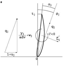
The flow is assumed to be inviscid, Cd = 0. At the blade element j the flow config­uration is as depicted in Fig. 10.11.

The local incidence is

Подпись: aПодпись: - tjForces and Moment(10.29)

where фj is called the flow angle and tj is the angle of twist at the element. The local lift coefficient is obtained from the result of thin airfoil theory or from an experimental or numerical profile lift curve C;(a). In thin airfoil theory, the lift is given by

d

Ci (a) = 2n(a + 2-) (10.30)

c

Подпись: d c Подпись: 1 2n Forces and Moment Подпись: (10.31)

d is the profile mean camber defined as

where d (x) is the equation of the camber line. According to the Kutta-Joukowski lift theorem, the lift force per unit span is perpendicular to the incoming flow, its

Fig. 10.11 Blade element

Подпись: z flow configuration

magnitude is L’ = pq Г and its orientation is 90° from the incoming flow direc­tion, rotating opposite to the circulation. q = q = ^(1 + u)2 + (ad – + wj2 is the normalized magnitude of the incoming flow velocity vector. This can be expressed mathematically as

~L ‘ = pU~cf Л URr~-f (10.32)

where dimensionless quantities have been introduced. ~j is the unit vector along the y-axis and Г < 0in Fig. 10.11. Upon a dimensionalization of the lift, the circulation is obtained as

1

Г] = — qjcJci (a j) (10.33)

The contribution of the blade element to thrust and torque can now be derived. Projection in the x-direction gives

dTj = L j cos фJRdyJ = – pUqj cos фJURГJRdyJ = —pU2 R2 гД^- + w Д dyj

Forces and Moment

or, upon integration

Projection of the lift force in the z-direction and accounting for the distance from the axis, the torque contribution reads

dTj = L’j sinфjRyjRdyj = pUqj sin ф^ URFjRyjRdyj = pU2R3rj (1 + Uj)yjdyj

(10.37)

Подпись: T = pU2 R3 Forces and Moment Подпись: (10.38)

which integrates to give

Подпись: CT Подпись: T 2 pU 2n R3 Forces and Moment Подпись: (10.39)

or, in dimensionless form

These results are for one blade. Total thrust and torque must account for all the blades.

Biot-Savart Law—Induced Velocities

Biot-Savart Law—Induced Velocities Подпись: (10.26)

The Biot-Savart formula reads

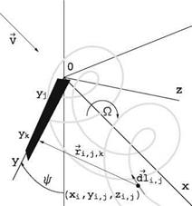
where d V i, jk is the induced velocity of the small element dl at a point k along a blade. ~ti, j, k is the distance vector having its origin at the vortex element and its extremity at point k. See Fig. 10.10.

For a three-bladed rotor, the u-component for a blade is given by

jx-1 jx-1

Uj = (Гк+1 – Гк)ak, j + Гкйк, j (10.27)

k=1 k=1

where the first term corresponds to influence of the vortex filaments k of each blade on the control point j on the lifting line and the tilde “~” term corresponds to the influence of the two other lifting line elements at yk on the control point j. Similarly, the w-components are obtained from the circulation with the influence coefficients ck, j and, with straight blades and zero coning angle, Ck, j = 0

Given the induced velocity components, the flow at the blade element can be analyzed and the local lift found. This is an approximation that amounts to neglecting the effect of the neighboring elements and considers each element in isolation, as if it were part of an infinite blade. Mathematically, this corresponds to neglecting the derivatives in the span direction compared to the other derivatives: dy ^ dx, .

This is appropriate, as has been found, for large aspect ratio wings and blades, that is those for which the chord is small compared to the span. This approach is called “strip theory”.

Adimensionalization—Discretization of the Vortex Sheets

Consider a rotor rotating at speed Q, placed in an incoming uniform flow with velocity V = (U, 0, 0) aligned with the turbine axis. We neglect the tower interfer­ence on the rotor flow. In a frame of reference attached to the rotor, the flow is steady. The tip speed ratio is defined as TSR = QR/U = 1/adv, which is also the inverse of the advance ratio, adv used as main parameter for propellers. Other dimensionless quantities are defined and used below:

Подпись: (10.14)

Подпись: c = Rc Подпись: (10.15)

x = Rx, y = Ry, z = Rz

Подпись:Подпись: (10.17)u = Uu, v = Uv, w = Uw

Г = URr

Подпись:Подпись:,3 5,

(10.18)

The bar “-” values correspond to dimensional variables, when the same letter is used. T is the thrust on the tower (N), Ct the thrust coefficient, t is the torque (N. m), Ct the torque coefficient, P the power (W), pT a dimensionless power coefficient, L’ is the local lift force per unit span, and Cl is the local lift coefficient.

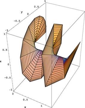
Each vortex sheet such as that in Fig. 10.8 is discretized as a lattice, shown unrolled in Fig. 10.9, to better explain the numerical scheme.

The circulation Д j is located at the grid points of the lattice (indicated by the circles). The blade is represented by a lifting line along the y-axis for blade 1 (thick solid line) and Д j represents the circulation inside the blade. The small elements of vorticity dl are located between the grid points and correspond either to trailed vorticity (in the x-direction in the presentation of Fig. 10.10) or shed vorticity (in the y-direction) that is present only when the flow is unsteady. When the flow is steady, as assumed here, the circulation is constant along a vortex filament, i. e. Г, j = Д j, Vi = 2,…, ix. The vorticity is given in terms of the differences in

Adimensionalization—Discretization of the Vortex Sheets

Fig. 10.10 Blade 1 and two trailing vortices—Schematic of Biot-Savart calculation
Adimensionalization—Discretization of the Vortex Sheets

Подпись: Уі Подпись: Zi Подпись: (10.19)
Adimensionalization—Discretization of the Vortex Sheets Adimensionalization—Discretization of the Vortex Sheets

circulation as АД j = Г, j+1_Д j for the trailed vorticity and АГі, j = Г, j_Гі-1, j (=0 here) for shed vorticity. The vortex element orientation is indicated by the arrow which represents positive АД j but the vector components account for the rolling of the sheet on a perfect helix. Let xi, y, zi represent the tip vortex of blade 1

The advance ratio is made to vary linearly from adv1 = (V + u)/QR at the rotor plane і = 1 to advix = (V + 2u)/QR after a few turns of the helix, then remains constant thereafter to the Trefftz plane і = ix. The mesh distribution in the x-direction is stretched from an initial value dx1 at the blade, to some location xstr — 1, using a stretching parameter s > 1 as

xt = xt-i + dxi_i, dxi = sdxi-i, і = 2,…,ix (10.20)

Beyond x = xstr the mesh is uniform all the way to the Trefftz plane xix — 20. In the y-direction, the mesh is discretized with a cosine distribution

1 j _ 1

yj = У0 + 2 (1 _ У0) cos в j, Q j = — – n, j = 1,…, jx (10.21)

2 jx 1

The trailed vortices are located between the mesh lines according to

1 2 j _ 1

П j = У0 + 2 (1 _ У0) cos в j, в j = —— —n, j = 1,…, jx _ 1 (10.22)

2 2(jx 1)

Accounting for the rolling of the sheet on a perfect helix, a small element of trailed vorticity has components

~ctl = {dxi, dyi, j, dzi, j}

Подпись: (10.23)1 1 1

-2(xi+1 – xi-1), -2(yi+1 – yi-1)nj, -2(zi+1 – zi-1)nj

whereas, a small element of shed vorticity has components

~dl = {dxi, dyi, j, dzi, j } = |0, 2 (yi-1 + yi )(nj – nj-1), 2(zi-1 + Zi )(nj – nj-1)

(10.24)

Application of the Biot-Savart formula provides the influence coefficients for the small elements, which are accumulated and stored in multidimensional arrays.

A particular treatment is made for the trailed elements closest to the lifting line and at the Trefftz plane. The former extend only half a cell with origin at 2 (x1 + x2) (see Fig. 10.9), and the latter extend from to to 2(xix-1 + xix), where a remainder accounts for the contribution downstream of the Trefftz plane. Note that in the case of the three-bladed rotor, the lifting lines themselves induce velocities on the other two (but not on themselves as straight blades). The same discretization applies for the calculation of the lifting line contributions for a three-bladed rotor, but now the small vortex element is located along the lifting line, having components

tl = {0, nj – n j-1, 0} , j = 2,…, jx – 1 (10.25)

in the case of blade 1, and АГ, j = A, j represents the circulation inside the blade.

Vortex Model and Strip Theory—The Goldstein Model

10.3.1 General Comments

The next level of modelization is the extension of the Prandtl lifting line theory, developed by Prandtl [6] for studying the inviscid flow past finite wings, to the flow past a rotor. The fundamental difference is in the shape of the vortex sheet. Behind a wing, the vortex sheet, often called “wake” even though the model is inviscid, can be assumed to be a surface generated by semi-infinite lines or vortices, originating at the

Подпись: Fig. 10.8 Vortex sheet from blade 1 and discretization as a vortex lattice
Vortex Model and Strip Theory—The Goldstein Model

sharp trailing edge of the wing and parallel to the incoming velocity vector. These vortices, according to the Biot-Savart formula, induce at the wing, represented as a single line (the lifting line), a velocity component w, perpendicular to the incoming flow, called “downwash”. In contrast, behind a rotor, the vortex sheets are modeled as perfect helices, obtained by rotating and translating a segment of straight line perpendicular and in the same plane as the axis. Each blade is represented by such a segment and generates an individual vortex sheet. The rotation corresponds to the rotor speed of rotation Q. The translation velocity varies from U + u at the rotor plane, to U + 2u far downstream, as shown in the one-dimensional flow theory. These helicoidal surfaces are made of helicoidal vortices that induce, according to the Biot-Savart formula, velocity components that affect the local incidences of the blade elements through the axial and azimuthal contributions. This is the Goldstein model [7]. See Fig. 10.8.

The simplifications associated with this model are important to understand. The fundamental choice is to prescribe the shape of the vortex sheets as perfect helices. This is often described as prescribed wake model or rigid wake model. The same is true of the wake model in the Prandtl lifting line theory, which is aligned with the undisturbed flow, yet yields very reasonable results. From a physical point of view, vortex sheets are surfaces of discontinuity of the velocity vector, wetted on both sides by the fluid and find an equilibrium position such that the pressure is continuous
across them. From a practical point of view, if the prescribed vortex sheets are close to the actual ones, the evaluation of the induced velocities will be accurate to first – order, as is the case of Prandtl’s theory and in the transfer of the tangency condition from the actual profile to the nearby axis in small disturbance theory of thin airfoils. In this method, the prescribed vortex structure satisfies an “equilibrium condition” by matching the absorbed rotor power with the power deficit in the far field, as will be seen later.

Another simplification consists in neglecting the rolling-up of the sheets edges, a well-known phenomena in aircraft aerodynamics associated with tip vortices that can create a hazard for small aircrafts flying in the tip vortices wake of large transport airplanes. Results indicate that keeping the sheets flat does not affect the accuracy of the simulation since the rolling-up does not change the vorticity content of the wake, only displaces it slightly.

The average axial velocity decreases behind the rotor. As a consequence, the stream tube diameter increases. The helicoidal vortex sheets would be expected to expand, however, this is not accounted for and possibly does not need to, since the rolling up of the sheets edges may partially counter this effect. It is believed that the rolling-up of the vortex sheets as well as the stream tube expansion are second-order effects, hence neglecting to account for them does not jeopardize the results.

The centrifugal and Coriolis forces are also neglected, which is acceptable for large wind turbines.

Free wake models have been developed in which the vortex sheets are allowed to find their equilibrium position as part of a Lagrangian iterative process in which vorticity is shed by the blades and convected downstream. Experience has shown that these methods are unstable. The vortex filaments tend to become disorganized and chaotic downstream of the rotor. Artificial dissipation is needed to prevent the calculation from diverging, which defeats the purpose of keeping the wake dissipation free, as expected with an inviscid model. Another aspect is that the number of vorticity laden particles increases with each time step and the run time per iteration increases quickly to excessive values as N3, where N is the number of particles. In the end, the free wake models are neither reliable nor efficient.

General 1-D Conservation Theorems—Actuator Disk Theory

As a first-order approximation, the flow past a horizontal axis wind turbine (HAWT) is treated as quasi-one dimensional. The stream tube captured by the rotor is described by its cross-section A(x) and the velocity V = (U + u, v, w) representing the

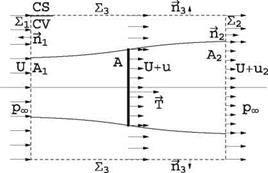
Fig. 10.6 Control volume/control surface for conservation theorems


General 1-D Conservation Theorems—Actuator Disk Theory

uniform flow plus a perturbation (u, v, w) in cylindrical coordinates. At the rotor disk, the velocity is continuous, but the pressure is allowed to jump, as if the rotor had infinitely many blades and was equivalent to a porous disk. The stream tube boundary downstream of the disk allows for a discontinuity in axial velocity between the flow inside and outside the stream tube, called slip stream. As a further simplification, the flow rotation behind the rotor is neglected, hence the azimuthal velocity component is zero (w = 0).

Consider a cylindrical control volume/control surface £3 with large diameter, containing the captured stream tube and bounded by two disks far upstream £ and far downstream £2 located in what is called the Trefftz plane, see Fig. 10.6. At the upstream boundary, the incoming flow is uniform and undisturbed with veloc­ity U aligned with the turbine axis, and pressure pOT. Downstream, at the Trefftz plane, the pressure returns to pOT, but the velocity inside the stream tube is less than the undisturbed value U outside of it. The flow is considered steady, incompress­ible (p = const.) and inviscid. Application of the conservation laws to the control volume/control surface yields the results known as the Rankine-Froude theory [2, 3] or actuator disk theory.

The conservation of mass (volume flow) reads:

(V 1 )dA = 0 (10.2)

CS

which can be broken into the various control surface contributions as

(-U£ + (U)£ – A2) + (U + U2)A2 + / (V. m)dA = 0 (10.3)

The cross section of the control volume is constant, hence £ = £2. After sim­plification, this reduces to

u2A2 + (m m)dA = 0

£3

which means that the deficit or excess of volume flow through the exit section is compensated by the flow across the lateral surface of the cylinder. The conservation of x-momentum reads

p(U + u’)(V.~n )dA = – pnxdA – T (10.5)

CS CS

where T represents the thrust exerted by the flow on the rotor/actuator disk. This is expanded as

pU(-U)£i+p(U)2(£2-A2)+p(U+U2)2A2 + pU(VV)dA =-T (10.6)

Note that, since pressure is constant and equal to рж on all control surfaces, it does not contribute to the momentum balance. The last term on the left-hand-side can be evaluated using the result of mass conservation. Solving for T:

T = —p(U + U2)U2 A2 = – thU2 (10.7)

where m = p(U + u)A = const. represents the mass flow rate in the stream tube and A = n R2, R denotes the radius of the rotor. Note that, since T > 0, then u2 < 0 for a turbine.

The steady energy equation applies to the stream tube with one-dimensional entrance and exit sections:

JA ( p + + gZ) dm = jA (~ + ‘у + gzj dm – Ws (10.8)

Ws = P represents the shaft work or power extracted (P < 0) from the flow by the rotor. Solving for P

n (p~ , (u + U2)2 V (Рж u2)

P = J + m – – + – ». (10.9)

After simplifying the above expression one finds

p = (u + m U2 (10.10)

The power is also given by P = – T(U + u) = (U + U)mU2. From this we conclude that u2 = 2u.

Results of this analysis can be summarized in terms of the rotor/actuator disk parameters

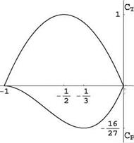
Fig. 10.7 Thrust and power coefficients versus axial induced velocity at the wind turbine rotor plane


General 1-D Conservation Theorems—Actuator Disk Theory

2


General 1-D Conservation Theorems—Actuator Disk Theory

Подпись: (10.12)P = 2p A(U + u)2u

General 1-D Conservation Theorems—Actuator Disk Theory Подпись: = 4 General 1-D Conservation Theorems—Actuator Disk Theory
General 1-D Conservation Theorems—Actuator Disk Theory

If one introduces the thrust and power coefficients

With change in sign, the power coefficient is also interpreted as the efficiency, n. These are shown in Fig. 10.7 in terms of Ц-.

The maximum value of the power coefficient CPmax | = 16/27 = 0.59 obtained for U = — 3 is known as the Betz limit [4]. The maximum thrust on the tower corresponds to Uu = —,, for which the final wake velocity is zero.

More elaborate models have been developed from this simple one-dimensional model with the addition of rotation in the wake by Joukowski [5] and others, but this requires making some empirical assumptions in order to be able to solve the equations. Instead of expanding more along these lines, we prefer devoting our time to a more realistic model, called the vortex model.

Horizontal Axis Wind Turbine

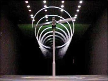
In the rest of the chapter, the attention will be devoted to horizontal axis wind turbines (HAWTs) which represent, today, the main type of wind power machines that are developed and installed in all parts of the world. Much efforts have been done in understanding better the flow past HAWT both experimentally and analytically. A major wind tunnel campaign has been carried out by the National Renewable Energy Laboratory (NREL) at the NASA Ames Research Center large 80′ x 120′ wind tunnel facility [1]. They used a two-bladed rotor of radius R = 5 m with blades equipped with the S809 profile. A picture of the wind turbine in the wind tunnel is shown in Fig. 10.5. Note in particular the well defined evolution of the tip vortex visualized with smoke emitted from the tip of one blade. One can count seven or eight turns with regular spacing, despite the dramatic distortion due to the encounter with the tower when the blade tip vortex passes in front of it.

Darrieus Rotor

According to Wikipedia (https://en. wikipedia. org/w/index. php? title=Darrieus_wind _turbine&oldid=581321514):

“The Darrieus wind turbine is a type of vertical axis wind turbine (VAWT) used to generate electricity from the energy carried in the wind. The turbine consists of a

Darrieus Rotor

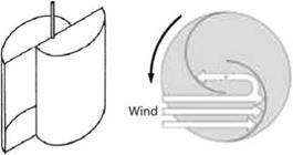
Fig. 10.3 Schematic drawings and operation of a two-scoop Savonius turbine, (from http://commons. wikimedia. org/wiki/File:Savonius_turbine. svg Author: Jaganath, http://commons. wikimedia. org/wiki/File:Savonius_Querschnitt. png Author Schargel)

number of aerofoils vertically mounted on a rotating shaft or framework. This design of wind turbine was patented by Georges Jean Marie Darrieus, a French aeronautical engineer in 1931.

The Darrieus type is theoretically just as efficient as the propeller type if wind speed is constant, but in practice this efficiency is rarely realized due to the physical stresses and limitations imposed by a practical design and wind speed variation. There are also major difficulties in protecting the Darrieus turbine from extreme wind conditions and in making it self-starting.

In the original versions of the Darrieus design, the aerofoils are arranged so that they are symmetrical and have zero rigging angle, that is, the angle that the aerofoils are set relative to the structure on which they are mounted. This arrangement is equally effective no matter which direction the wind is blowing—in contrast to the conventional type, which must be rotated to face into the wind.

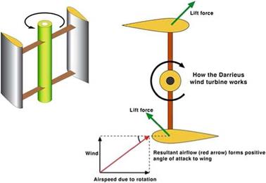
When the Darrieus rotor is spinning, the aerofoils are moving forward through the air in a circular path. Relative to the blade, this oncoming airflow is added vectorially to the wind, so that the resultant airflow creates a varying small positive angle of attack (AoA) to the blade. This generates a net force pointing obliquely forwards along a certain ‘line-of-action’. This force can be projected inwards past the turbine axis at a certain distance, giving a positive torque to the shaft, thus helping it to rotate in the direction it is already travelling in. The aerodynamic principles which rotates the rotor are equivalent to that in autogiros, and normal helicopters in autorotation.

As the aerofoil moves around the back of the apparatus, the angle of attack changes to the opposite sign, but the generated force is still obliquely in the direction of rotation, because the wings are symmetrical and the rigging angle is zero. The rotor spins at a rate unrelated to the windspeed, and usually many times faster. The energy arising from the torque and speed may be extracted and converted into useful power by using an electrical generator.

The aeronautical terms lift and drag are, strictly speaking, forces across and along the approaching net relative airflow respectively, so they are not useful here. We really want to know the tangential force pulling the blade around, and the radial force acting against the bearings.

Darrieus Rotor

Fig. 10.4 Schematic of a Darrieus turbine: perspective (left); top view (right) (from https://en. wikipedia. org/wiki/File:Darrieus. jpg Author: Grahamuk)

When the rotor is stationary, no net rotational force arises, even if the wind speed rises quite high—the rotor must already be spinning to generate torque. Thus the design is not normally self starting. It should be noted though, that under extremely rare conditions, Darrieus rotors can self-start, so some form of brake is required to hold it when stopped. See. Fig. 10.4.

One problem with the design is that the angle of attack changes as the turbine spins, so each blade generates its maximum torque at two points on its cycle (front and back of the turbine). This leads to a sinusoidal (pulsing) power cycle that complicates design. In particular, almost all Darrieus turbines have resonant modes where, at a particular rotational speed, the pulsing is at a natural frequency of the blades that can cause them to (eventually) break. For this reason, most Darrieus turbines have mechanical brakes or other speed control devices to keep the turbine from spinning at these speeds for any lengthy period of time…

…In overall comparison, while there are some advantages in Darrieus design there are many more disadvantages, especially with bigger machines in MW class. The Darrieus design uses much more expensive material in blades while most of the blade is too near of ground to give any real power. Traditional designs assume that wing tip is at least 40 m from ground at lowest point to maximize energy production and life time. So far there is no known material (not even carbon fiber) which can meet cyclic load requirements”.

Darrieus Rotor

Fig. 10.5 NREL turbine in NASA Ames 80′ x 120′ wind tunnel, from Ref [1]

Savonius Rotor

According to Wikipedia (https://en. wikipedia. org/w/index. php? title=Savonius_wind _turbine&oldid=555948336):

“Savonius wind turbines are a type of vertical-axis wind turbine (VAWT), used for converting the power of the wind into torque on a rotating shaft. They were invented by the Finnish engineer Sigurd J. Savonius in 1922. Johann Ernst Elias Bessler (born 1680) was the first to attempt to build a horizontal windmill of the Savonius type in the town of Furstenburg in Germany in 1745. He fell to his death whilst construction was under way. It was never completed but the building still exists.

Savonius turbines are one of the simplest turbines. Aerodynamically, they are drag-type devices, consisting of two or three scoops. Looking down on the rotor from above, a two-scoop machine would look like an S shape in cross section. Because of the curvature, the scoops experience less drag when moving against the wind than when moving with the wind. The differential drag causes the Savonius turbine to spin. Because they are drag-type devices, Savonius turbines extract much less of the wind’s power than other similarly-sized lift-type turbines. Much of the swept area of a Savonius rotor is near the ground, making the overall energy extraction less effective due to lower wind speed at lower heights.

Savonius turbines are used whenever cost or reliability is much more impor­tant than efficiency. For example, most anemometers are Savonius turbines, because efficiency is completely irrelevant for that application. Much larger Savonius turbines have been used to generate electric power on deep-water buoys, which need small amounts of power and get very little maintenance. Design is simplified because, unlike horizontal axis wind turbines (HAWTs), no pointing mechanism is required to allow for shifting wind direction and the turbine is self-starting. Savonius and other vertical-axis machines are not usually connected to electric power grids. They can sometimes have long helical scoops, to give smooth torque.

The most ubiquitous application of the Savonius wind turbine is the Flettner Ventilator which is commonly seen on the roofs of vans and buses and is used as a cooling device. The ventilator was developed by the German aircraft engineer Anton Flettner in the 1920s. It uses the Savonius wind turbine to drive an extractor fan. The vents are still manufactured in the UK by Flettner Ventilator Limited.

Small Savonius wind turbines are sometimes seen used as advertising signs where the rotation helps to draw attention to the item advertised”. See Fig. 10.3.

Aerodynamics Forces—Lift and Drag

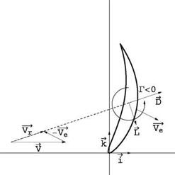
The aerodynamic forces acting on an obstacle are decomposed into lift and drag components, F = D + L, the drag being a force aligned with the incoming velocity as seen by the body and the lift being a force perpendicular to it. This decomposition is made in a frame of reference attached to the blade element, as pertinent to a moving machine. This is depicted in Fig. 10.2. The wind velocity V, and the velocity of the element V e in the absolute frame give the velocity of the fluid relative to the obstacle as

Vr = V – Ve (10.1)

The drag is aligned and in the direction of ~Vr. The lift is rotated 90° opposite the circulation Г developed inside the profile (Fig. 10.1).

Some wind machines are drag-driven, such as the Savonius wind turbine, whereas some are lift-driven as the Darrieus and the wind-axis turbines. The drag-driven machines are less efficient as the velocity of the device is always less than the wind velocity. Such systems are more useful as propulsive than power producing systems. The 15th century galleon such as Columbus “Santa Maria” belongs to the category of drag-driven systems. The modern racing sail boats use their sails as aircraft wings and are examples of lift-driven systems. A drag-driven device rotating about the y-axis (into the paper in Fig. 10.2) will correspond to V e ~ Ve i where Ve < V and the lift force is either zero or does not contribute to the power P = F. V ~ DV. A lift-driven machine rotating about the x-axis (wind-axis turbine) will correspond to V e ~ – Vek and with (L/D)max ~ 10, the lift force will be the component contributing primarily to power generation.

Aerodynamics Forces—Lift and Drag

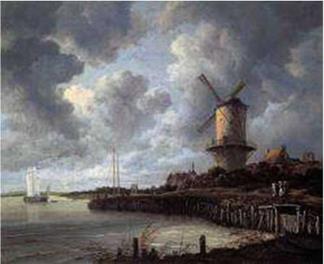
Fig. 10.1 Tower Mill at Wijk bij Duurstede by J. van Ruysdael, (from https://en. wikipedia. org/ wiki/File:The_Windmin_at_Wijk_bij_Duurstede_1670_Ruisdael. jpg Rijksmuseum Amsterdam)


z

Aerodynamics Forces—Lift and Drag

Fig. 10.2 Lift and drag forces acting on a moving blade element


Wind Turbine and Propeller Aerodynamics—Analysis and Design

Wind turbines and propellers are very similar from the aerodynamics point of view, the former extracting energy from the wind, the latter putting energy into the fluid to create a thrust. The main part of this chapter will be devoted to wind turbine analysis and design, as this is currently a major area of research. But much of the theory and numerics is applicable to propellers. Section 10.9 will discuss some results pertinent to propellers. By convention, the power absorbed by a wind turbine rotor will be negative, whereas, that provided by the power plant of a propeller driven system will be positive.

10.1 Introduction—the Different Types of Wind Turbines

Wind-driven machines can be classified according to the orientation of their axis relative to the wind direction. Cross wind-axis machines have their axis in a plane perpendicular to the incoming wind velocity vector; wind-axis machines have their axis parallel to the incoming air flow. This fundamental difference impacts the study of these two types of machines: under the simplest of assumptions of constant wind speed, constant rotation speed and isolated rotor (neglecting support interference), the flow past a wind-axis machine, considered in a frame rotating with the blades is steady, whereas, for a cross wind-axis machine it is always unsteady. Unsteady flows are more complex and costly to analyze analytically and numerically. For this reason we will focus our attention on wind-axis machines. Sources of unsteadiness for wind-axis machines are yaw, when the wind direction is not aligned with the rotor axis, tower interference, earth boundary layer, wind gusts and, ultimately, blade deflection. This will be considered in Sect. 10.6 on unsteady flow. Prior to that, Sect. 10.2 will discuss the general 1-D conservation theorems, commonly called actuator disk theory. Section 10.3 will introduce the vortex model based on Goldstein “airscrew theory” with the treatment of the vortex sheets and the derivation of the torque and thrust in the spirit of the Prandtl lifting line theory. A discretization of the

© Springer Science+Business Media Dordrecht 2015 327

J. J. Chattot and M. M. Hafez, Theoretical and Applied Aerodynamics,

DOI 10.1007/978-94-017-9825-9_10

vortex sheet as a lattice is proposed for the application of the Biot-Savart law. The next section, Sect. 10.4, deals with the design of the optimum rotor, discusses the minimum energy condition of Betz and gives a more general result for the optimum condition. Section 10.5 is devoted to the analysis problem, that is of finding the solution of the flow past a given rotor. A technique for handling high incidences and stalled flow on the blades is detailed and illustrated with an example. In Sect. 10.6 the extension of the method to unsteady flow is presented. The key issues are discussed. The effects of yaw and tower interference are assessed and the limits of the method shown by comparisons with experiments. Section 10.7 discusses the hybrid method of coupling a Navier-Stokes code with the vortex model as a means to achieve high fidelity modeling of viscous effects. This is followed, in Sect. 10.8, by perspectives and further development currently under way.