Category Theoretical and Applied Aerodynamics

Viscous/Inviscid Interaction Procedures Based on Domain Decomposition Techniques

In these zonal procedures, the flow field is divided into two regions. To patch the two regions, an overlap layer, where the equations on both sides are valid, must exist.

Quarteroni and Valli [37] studied direct coupling of the Euler and Navier-Stokes equations. The motivation is clear. Away from the body, the grid is usually coarse and the viscous terms are not resolved and are not needed anyway, hence they are switched off. It turns out that errors can be reflected at the interface. Some fixes are possible however, but the general case is complicated.

To demonstrate some of these ideas, we will use stream function/vorticity formu­lation for incompressible two-dimensional steady laminar flow. The Navier-Stokes equations in Cartesian coordinates are given by

Viscous/Inviscid Interaction Procedures Based on Domain Decomposition Techniques Viscous/Inviscid Interaction Procedures Based on Domain Decomposition Techniques
Подпись: (9.86)

where

The boundary conditions on a solid surface are given in terms of ф (u is unknown there), namely ф = const and дф/дn = 0, where n is the normal direction to the surface. For multi-connected domain, special treatment is required to assign the level of ф on each closed body.

For high Reynolds number flows, upwind differences are used for the convective terms of the vorticity equation. Moreover, thin layer approximations (or partially parabolized Navier-Stokes equations) may be used, where the second derivatives in the tangential direction of the main flow in the vorticity equation, uxx, is neglected.

Notice, neglecting i^xx compared to фуу as well, will lead to the boundary layer approximations and the equations become parabolic, where upstream effect is not possible. hence, the name of partially parabolized equations, where only uxx is neglected.

Obviously, the flow in the whole domain can be simulated using a stretched grid and iterative methods of the discrete equations coupled, for example successive line iteration can be used with 2 x 2 block tridiagonal solver, marching in the flow direction. Several sweeps are required for convergence.

Now, one can split the domain in two regions. in the outer one, vorticity vanishes and the vorticity equation is not needed. The question is where should the interface be? One can calculate the viscous terms, from the previous iteration, and if they are relatively small, they are switched off. Here, for convenience, the two regions are fixed a priori using rough boundary layer estimates.

To see the effect of switching off the vorticity in the outer region, the same numer­ical method described before for the whole domain is used. Comparison of accuracy of the results (i. e. friction drag) and the convergence of iterations for different sizes of the viscous region may assess the merit of this zonal approach (see Halim and Hafez [38], Tang and Hafez [39]), Hafez and Guo [40].

To take advantage of the different scales involved, one may solve the viscous and inviscid flow problems separately, hence a coupling procedure is needed. Two possibilities will be discussed.

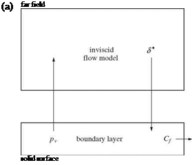
In the first method, the viscous flow calculations provide фу as boundary condition for the inviscid flow calculations, while the inviscid flow calculations provide in return фі and (фп)i for the viscous flow calculations, as shown in Fig. 9.11.

Again, the size of the overlap region must be determined based on the accuracy of the results and the convergence of iterations.

Viscous/Inviscid Interaction Procedures Based on Domain Decomposition Techniques

far field

flow

direction

solid body

Fig. 9.11 Sketch for method 1

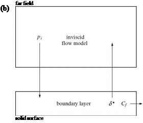
In the second method, a coupling formula is introduced along the interface. The only requirement for the coupling formula is to be consistent (i. e. it does not upset the converged solution), see for example Carter’s formula [25] or semi-inverse incom­pressible flow example used by Cebeci [28] for transonic flow calculations. It is argued, however, a “better” coupling formula can be introduced if the flow physics is taken into consideration.
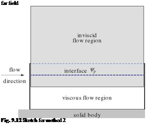
Подпись: far field Fig. 9.12 Sketch for method 2

An application to our simple problem is shown in Fig. 9.12.

According to Carter, a coupling formula for a semi-inverse implicit procedure could be

ФП+1 = ФПp + a(ui – uv) (9.88)

where ui is the velocity component calculated from the inviscid flow region and uv is the velocity component calculated from the viscous flow region.

Подпись: фі, Подпись: фi, Viscous/Inviscid Interaction Procedures Based on Domain Decomposition Techniques Подпись: 2ФП p + ФП p-1 Ay2 Подпись: (9.89)

In the above formula, a is a free parameter. However, since the interface must lie in a region where both the viscous and inviscid flow equations are valid, one can choose the coupling formula as follows

The first term on the right-hand-side is evaluated at level n + 1, leading to an implicit formula for фі, p and requires a tridiagonal solver.

Подпись: (9.90)

Подпись: 2 д25ф гд5ф (1 - M ) — + ^ + аЗф dx2 dx
Подпись: T( + r(P ? dx p dx dy p dy

In general, the interface equation may be the governing equation for ф, hence the coupling formula may be given for low speed flow, by

where 5ф is the correction, M is the local Mach number and p is the artificial density. Notice a should be zero for supersonic flow regions, according to the Fourier analysis!

In the above method, the overlap region consists of only three horizontal lines. The updated values of Ф p is used for both the inviscid and viscous flow regions. The latter requires also фі_p+1 to calculate ui = (фі_p+1 – фі, p)/Ay.

In general, methods with larger overlap region have better convergence. In the fol­lowing, methods using all the viscous region as an overlap region will be considered and their merits will be discussed.

Consider the same simple problem with the following splitting, method 3, Fig.9.13:

In this method, the streamfunction equation is solved in the whole domain, assum­ing w is known (in the viscous layer) and using only the no penetration boundary

Подпись: far fieldПодпись: flowПодпись:Fig. 9.13 Sketch for method 3

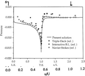
condition on the solid surface (ф = const). The no slip condition, фп = 0, is not imposed on this step of the calculations. The viscous flow is solved as usual with the two interface conditions and the no slip and no penetration conditions at the solid surface. The vorticity calculated, in the viscous flow region, is used as a forcing function distributed over part of the domain for the first calculations. The overlap region, now, is the whole viscous flow region. Moreover, the forcing function, ш, is distributed over the whole viscous flow region. An example of this method is given in [39] for the trailing edge flow and good comparison with the full Navier-Stokes equations and triple deck theory calculations is shown.

The same example is solved in [41], using potential formulation augmented with velocity correction in the viscous layer. The governing equations are

Подпись: (9.91) (9.92) Подпись: (9.93)Подпись: (9.94)дф

u= + u+U

д x

дф

dy

The continuity equation becomes

д2ф д2ф ди

дх2 + ду2 дх

In the momentum equation

Подпись: дp 1 д2и дх + Re ду2 ди ди и + v дх ду

the pressure term is approximated via linearized Bernoulli’s law, p = p0 – pUи. Notice, и = фх varies with у inside the viscous flow region. This formulation is similar to Cousteix’ recent analysis [23].

The augmented potential equation is solved everywhere with the forcing function – их, distributed in the viscous layer. Only the no penetration фп = 0 boundary condition at the solid surface is imposed. The momentum equation is solved for и with the pressure gradient given in terms of фх as a forcing function and the no slip boundary condition at the solid surface and и = фх + U at the interface (i. e. и = 0 there).

A more general formulation is adopted in [41] for the simulation of viscous flow over a rotating cylinder, where

дф

и = + и + U дх

(9.95)

дф

v = + v ду

(9.96)

Viscous/Inviscid Interaction Procedures Based on Domain Decomposition Techniques

Both the x – and the у-momentum equations are used to update и and v. The pressure terms are still evaluated based on Bernoulli’s law and in terms of фх and

фу.

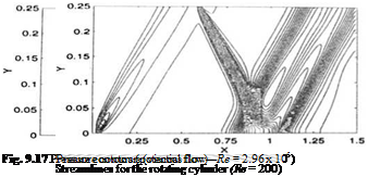
The results for finite flat plate and rotating cylinders are shown in Figs. 9.14, 9.15 and 9.16.

Finally, the approximation of the pressure in terms of фх and фу, using Bernoulli’s law can be removed. The pressure can be evaluated by integrating the normal momen­tum equation inwards, from the interface to the solid body and thus the formulation, in the viscous flow region, becomes completely equivalent to the Navier-Stokes equa­tions. This variable fidelity formulation has been used to simulate shock wave/laminar boundary layer interaction and the comparison with results of Navier-Stokes equa-
Viscous/Inviscid Interaction Procedures Based on Domain Decomposition Techniques

Fig. 9.16

Fig. 9.18 tionsis given in Ref. [42]. Figures 9.17 and 9.18 from Ref. [42] show the wall pressure distribution and the Mach contours respectively.

The same method has been used to simulate transonic flows with shocks over airfoils and wings, see Hafez and Wahba [43-45]. It is claimed that the domain decomposition technique allows to use multigrid and upwind schemes more effl- ciently.

Viscous/inviscid interaction procedures for unsteady flows are discussed in Ref. [46, 47].

9.2 Summary of Chapter 9

Two main approaches are discussed in this chapter. The first one is based on the dis­placement thickness concept and the inviscid flow and boundary layer calculations are coupled through the displacement thickness and the streamwise pressure distri­bution. The inviscid flow and boundary layer calculations can be based on integral formulations or finite discrete approximation techniques and the four possibilities are covered. In the case where both calculations are based on integral formulations, quasi-one dimensional flow in a nozzle is studied via Pollhausen method, extended to compressible flow by Gruschwitz and by Oswatisch, as well as incompressible and supersonic flows over thin airfoils. Also, the potential flow calculation based on the streamfunction formulation, for two-dimensional flows, is coupled with the integral momentum equation. Coupling Euler calculations with boundary layer calculations are discussed in details, using several ideas.

Finally, coupling the numerical solution of the field equations of inviscid and boundary layer equations is briefly reviewed.

In the second approach, heterogeneous domain decomposition is used to cou­ple potential and Euler calculations with solutions of boundary layer or thin layer approximation of the Navier-Stokes equations. Streamfunction/vorticity formulation is described to demonstrate the concept, and potential formulation augmented with vorticity correction terms is used for compressible flow calculations.

References

1. McDevitt, J. B.: Supercritical flow about a thick circular-arc airfoil. NASA TM 78549 (1979)

2. Chattot, J.-J.: Computational Aerodynamics and Fluid Dynamics: An Introduction. Springer, New York (2002)

3. Hafez, M., Palaniswamy, S. Mariani, P.: Calculations of transonic flows with shocks using Newton’s method and direct solver. Part II. AIAA paper 88-0226 (1988)

4. Wieghardt, K.: Uber einen Energiesatz zur Brechnung Laminarer Grenzschichten. Ingen-Arch. 16, 23-243 (1948)

5. Walz, A.: Application of Wieghardt’s Energy Theorem to Velocity Profiles of One-Parameter in Laminar Boundary Layers. Rep. Aero. Res. Coun, London, No 10133. (1946)

6. Truckenbrodt, E.: An approximate method for the calculation of the laminar and turbulent boundary layer by simple quadrature for two dimensional and axially symmetric flow. JAS 19, 428-429 (1952)

7. Tani, I.: On the approximate solution of the laminar boundary layer equations. JAS 21,487-495 (1954)

8. Holt, M.: Numerical Methods in Fluid Dynamics. Springer, New York (1984)

9. Schlichting, H.: Boundary Layer Theory. McGraw Hill, New York (1979)

10. Rosenhead, L. (ed.): Laminar Boundary Layers. Oxford University Press, Oxford (1963)

11. Swafford, T., Huddleston, D., Busby, J., Chesser, B. L.: Computation of Steady and Unsteady Quasi-One-Dimensional Viscous/Inviscid Interacting Internal Flows at Subsonic. Transonic and Supersonic Mach Numbers. Final Report NASA Lewis Research Center (1992)

12. Stewartson, K.: The Theory of Laminar Boundary Layers in Compressible Fluids. Oxford University Press, Oxford (1964)

13. Gruschwitz, E.: Calcul Approche delaCouche Limite Laminaire en Ecoulement Compressible sur une Paroi Non-Conductrice de la Chaleur, ONERA, Publication No. 47 (1950)

14. Oswatitsch, K.: Gas Dynamics. Academic Press, New York (1956)

15. Liepmann, H., Roshko, A.: Elements of Gas Dynamics. Wiley, New York (1957)

16. Whitfield, D., Swafford, T., Jackocks, J.: Calculations of turbulent boundary layers with sepa­ration and viscous-inviscid interaction. AIAA J. 19(10), 1315 (1981)

17. Moses, H., Jones, R., O’Brien, W.: Simultaneous solution of the boundary layer and freestream with separated flow. AIAA J. 16(1), 419-426 (1978)

18. Le Balleur, J.-Cl.: Numerical flow calculation and viscous-inviscid interaction techniques, (1978)

19. Johnston, W., Sockol, P.: Matching procedure for viscous-inviscid interactive computations. AIAA J. 17(6), 661-665 (1979)

20. Murman, E., Bussing, T.: On the coupling of boundary-layer and Euler equations. Numerical and Physical Aspects of Aerodynamic Flows II., Springer, New York (1984)

21. Whitfield, D., Thomas, J. L.: Viscous-inviscid interaction using euler and inverse boundary – layer equations. Computational Methods in Viscous Flows. Pineridge Press, Swansea, (1984)

22. Wigton, L., Yoshihara, H.: Viscous-inviscid interaction with a three-dimensional inverse bound­ary layer code. Numerical and Physical Aspects of Aerodynamics. Springer (1984)

23. Cousteix, J., Mauss, J.: Asymptotic Analysis and Boundary Layer. Springer, New York (2007)

24. Catherall, D., Mangler, K. W.: The integration of the two-dimensional laminar boundary-layer equations past a point of vanishing skin friction. J. Fluid Mech. 26, 163-182 (1966)

25. Carter, J.: A new boundary-layer inviscid iteration technique for separated flow. AIAA paper 79-1450 (1979)

26. Brune, G. W., Rubbert, P., Nark, T.: A new approach to inviscid flow/boundary layer matching. AIAA paper 74-601 (1974)

27. Veldman, A.: New, quasi-simultaneous method to calculate interactive boundary layer. AIAA J. 19(1), 79-85 (1981)

28. Cebeci, T.: An Engineering Approach in Calculations of Aerodynamic Flows. Springer, New York (1999)

29. Wigton, L. and Holt, M.: Viscous-inviscid interaction in transonic flow. AIAA paper 81-1003 (1981)

30. Lock, R. C., Williams, B. R.: Viscous-inviscid interactions in external aerodynamics. Prog. Aerosp. Sci. 24(2), 51-171 (1987)

31. Stewartson, K.: Multistructured boundary layers on flat plates and related bodies. Adv. Appl. Mech. 14, 145-239 (1974)

32. Reynher, T., Flugge-Lotz, I.: The interaction of a shock wave with a laminar boundary layer. Int. J. Nonlinear Mech. 3(2), 173-199 (1968)

33. Drela, M., Giles, M. D.: Viscous-inviscid analysis of transonic and low Reynolds number air­foils. AIAA J. 25(10), 1347-1355 (1987)

34. Neiland, V.: Flow behind the boundary layer separation point in a supersonic stream. Fluid Dyn. 6, 378-384 (1971)

35. Sychev, V.: On laminar separation. Fluid Dyn. 7, 407-417 (1972)

36. Ryzhov, O.: Nonlinear Stability and Transition, to be Published by World Scientific. (2014)

37. Quarteroni, A., Valli, A.: Domain Decomposition Methods for Partial Differential Equations. Oxford University Press, Oxford (1999)

38. Halim, A., Hafez, M.: Calculation of Separation Bubbles using Boundary-layer Type Equations. Computational Methods in Viscous Flows. Pineridge Press, Swansea (1984)

39. Tang, C., Hafez, M.: Numerical simulation of steady compressible flows using zonal formula­tion. Part I Part II, Comput. Fluids 7-8, 989-1001 (2001)

40. Hafez, M. and Guo, W.: Simulation of steady compressible flows based on Cauchy/Riemann equations and Crocco’s relations. Part I and Part II, Int. J. Numer. Methods Fluids, 25, 1-12 and, 26, 325-344 (1998)

41. Hafez, M., Wahaba, E.: Incompressible viscous steady flow over finite plate and rotating cylin­der with suction. Comput. Fluid Dyn. J. 13(3), 571-584 (2004)

42. Hafez, M., Wahaba, E.: Hierarchical formulations for transonic flow simulations. Comput. Fluid Dyn. J. 11(4), 377-382 (2003)

43. Hafez, M., Wahaba, E.: Numerical simulations of transonic aerodynamic flows based on hier­archical formulation. Int. J. Numer. Methods Fluids, 47(6-7), 491-516 (2005)

44. Hafez, M., Wahaba, E.: Simulations of viscous transonic flows over lifting airfoils and wings. Comput. Fluids 36(1), 32-52 (2006)

45. Hafez, M., Wahaba, E.: Viscous/inviscid interaction procedures for compressible aerodynamic flow simulations. Comput. Fluids 35(7), 755-761 (2006)

46. Shatalov, A., Nakajima, M., Hafez, M.: Simulation of unsteady incompressible flows using Helmoltz-velocity decomposition. Comput. Fluid Dyn. J. 14(3), 246-254 (2005)

47. Shatalov, A., Nakajima, M., Hafez, M.: Numerical simulations of unsteady laminar incom­pressible flows using viscous/inviscid interaction procedures. Comput. Fluid Dyn. J. 15(3), 246-254 (2005)

Coupling Numerical Solutions of Partial Differential

Equations of both the Inviscid and Viscous Flow Regions

9.1.4.1 Coupling the Numerical Solution of Boundary Layer Equations with the Numerical Solution of the Inviscid Flow Equations

In this case, some coupling procedures discussed before as inverse and semi-inverse or simultaneous iterations are used. For incompressible flows, Moses et al. [17] intro­duced a simple effective method where the inviscid flow and viscous flow equations are solved coupled along vertical lines extending from the boundary layer to the outer inviscid flow region, governed by elliptic equation for the streamfunction (or potential function). hence, the line relaxation method of the inviscid flow equation is augmented at each streamwise location with the discrete boundary layer equa­tions, coupled through the displacement thickness and many sweeps are required for convergence. The parabolic nature of the boundary layer equations in the case of attached flows, is not utilized in this method. However, the method can be used for the simulation of separated flows.

Also, the method can be extended to transonic flows where the inviscid flow equations are nonlinear and of mixed-type for both potential and Euler formulations. In this regard, one should mention the successful method introduced by Drela and Giles [33].

Higher order boundary layer equations, including curvature effects and pressure variation normal to the main flow direction, have been used and have led to the triple deck theory (see Stewartson [31], Neiland [34] and Sychev [35]). The latter has been proved to be successful for the trailing edge and separated laminar flows. Attempts to extend the theory to turbulent flows are faced with the problem of turbulence modeling. Extensions to unsteady flows are in progress (see Ryzhov [36]).

Coupling the Numerical Solution of the Partial Differential Equations of the Viscous Flow with the Integral Equations of the Outer Inviscid Flows

9.1.3.1 Coupling the Numerical Solution of Boundary Layer Equations with Integral Representation of the Inviscid Flows:

Incompressible Flows

For incompressible flows, the outer flow region is approximated by integrals over the body and the wake in terms of the shape of the body and the displacement thickness, as discussed before. The boundary layer equations are discretized using finite difference methods. The velocity u at the outer edge of the boundary layer is related to the distribution of the displacement thickness. Iterative methods must be used to solve these coupled nonlinear equations. Many sweeps of the boundary layer are required and upstream effects are recovered through the coupling with the inviscid flow integral representation. Separated flows can be simulated using upwinding scheme for the convective terms of the streamwise momentum equation. This procedure is used by many authors, see for example Lock and Williams [30]. A similar procedure is used also in triple deck theory, see Stewartson’s review [31].

9.1.3.2 Coupling the Numerical Solution of Boundary Layer Equations with Integral Representation of the Inviscid Flows: Supersonic Flows

For supersonic flows, the inviscid outer region can be represented by the Ackeret formula. The finite difference approximations of the boundary layer equations can be solved by marching in the direction of the flow in case of no separation. local iterations at each step are still needed. This procedure was used in the sixties by Reynher and Flugge-Lotz [32] to study shock wave/ boundary layer interaction. For separated flows, they switch off the uux term in the momentum equation since u is negative but very small in the separated region. Such strategy (FLARE approximation) has been adopted by others to avoid numerical instability of the calculations of separated flows, although the results are at best first order accurate this way. Also, the simple relation between the pressure and the deflection angle for the outer flow region limits the validity of the calculations to Small disturbance linearized supersonic aerodynamic problems.

Coupling Euler Calculations with Boundary Layer Integral Momentum Equations

As discussed before, the displacement thickness is determined such that the mass flow rate over the displaced body, at a given station, based on an equivalent inviscid flow will be equal to the mass flow rate of the viscous flow profile over the original body. Let y = yu represent the ordinate of the upper surface and in short S* = SU represent the displacement thickness along the upper surface of the airfoil.

If the Euler equations are used to represent the inviscid flow, instead of the poten­tial flow equation, then additional considerations are necessary, since beside the continuity equation, momentum and energy equations are involved.

Le Balleur [18], has considered the general problem of matching and in the follow­ing his defect formulation will be discussed. The reader is also referred to Johnston and Soskol [19], Murman and Bussing [20] and Whitfield et al. [21] for more appli­cations of one and two dimensional problems. Three dimensional flows over wings are considered in Ref. [22].

In the Le Balleur defect formulation, the equivalent inviscid flow problem and the viscous flow problem have an overlap region, starting from the wall and the wake center line and extends to cover the whole viscous layer. Outside the viscous layer, the viscous stresses are assumed negligible compared to the inertia terms.

For steady 2-D flows, at a given station x = constthe inviscid flow equations are

Подпись:df dg

dx + dy

where

pu

pv

f=

pu2 + p

, and g =

puv

puv

pvz + p

pu H

pv H

Coupling Euler Calculations with Boundary Layer Integral Momentum Equations Подпись: (9.51)

and

while the viscous flow equations are given by

Подпись:dF dG _

dx + dy S

where S denotes the viscous and heat transfer terms in Navier-Stokes or thin layer approximation equations.

The asymptotic matching condition is

lim (f – F) = 0 (9.53)

y^0

The defect formulation takes into consideration the variation of inviscid flow variables, including the pressure, across the boundary layer. The defect equation in vector form reads

Подпись:d (f – F) d (g – G) =

dx dy

Integration across the layer gives for example

d

pv(x, 0) = (pu — pu) dy (9.55)

dx 0

where the bar denotes the viscous flow variables.

To first order approximation, the normal momentum equation reduces to p = p across the viscous layer and the integral equations for the continuity, streamwise momentum equations are

pv(x, 0) = dL (pqs*)

Подпись:Подпись: (9.58) (9.59) puv(x, 0) = pq2(в + —5*’) — pq2

ax q 2

where q2 = u2 + v2.

co h

Spq (x, 0) = (pu — p—) dy — (pu — p—) dy

0 0

+—5*^ pq2(x, 0) = J {pu2 — pu2^ dy — J {pu2 — pu2^ dy

and h > 5.

Le Balleur considered also the effect of curvature of the wake which is not dis­cussed here.

Following Whitfield, the energy equation, using no porosity and no slip at adiabatic surface, one obtains

Подпись: (9.60)dh

pv H (x, 0) — puH — pmH dy

dx 0

To avoid these extra calculations, an approximation consistent with boundary layers with Pr = 1 is used, where H = H = H0, hence

Подпись: (9.61)dh

pv H (x, 0) — H0 puH — puH dy

dx 0

which is the same as the equation obtained from the integration of the continuity equation.

Murman and Bussing [20] applied Le Balleur’s defect formulation for compress­ible flow in a convergent-divergent nozzle and used boundary layer approximations for the viscous flows. The matching conditions used are

u = и, H = H, p = p, and v = v, at h > 5 (9.62)

The first three conditions are used in the boundary layer calculations. Therefore, one additional condition must be specified to enforce the matching. The boundary conditions for Euler equations will be derived using the fourth condition in three cases: the equivalent inviscid flow at the boundary layer thickness y = yu + 5; or at the original body y = yu; or at the displaced body y = yu + 5*.

Integrating the continuity equation from the body surface to S yields

Подпись:d rS dS

Coupling Euler Calculations with Boundary Layer Integral Momentum Equations Coupling Euler Calculations with Boundary Layer Integral Momentum Equations

pudy – (pu)s — + (pv)s = 0 dx 0 dx

and since (pu)S = (pu)S, the above equation reduces to

dS d

(pv)s = (pu)s dx – dx ((pu)s (S – S )) (9.66)

This is the entrainment equation, where the second term represents the entrained mass flow rate. The second term is usually negative and it is the only boundary condition at y = S required for the Euler equations calculations (subsonic boundary condition).

Instead, if the continuity equation is integrated from S* to S and enforcing the matching conditions, one obtains

dS* d S ( pu,

(pv)l’ =(puk – dx + dx (pu)SJs, (‘ – TdXdJ dy (9’67)

If the gradient of the equivalent inviscid flow is negligible in the region S* < y < S, then the last term drops and the flow is tangent to the S* surface. In this case, the no penetration surface boundary condition is imposed for the Euler calculations.

If the inner boundary condition of the inviscid flow is located at the original surface, the standard definition of S* is used, and the transpiration boundary condition reads

(pv)0 = dx {(pu)§S*) (9.68)

In most regions, the body will be an inflow boundary, which means that three characteristics are pointing into the domain and one points out. The above matching condition provides only one. The inviscid flow is not uniquely determined! (For potential flow, the total pressure and total enthalpy are constant and the transpiration boundary condition uniquely determines the flow).

To determine the inviscid flow governed by the Euler equations, Johnson and Sockol integrated the momentum and energy equations from the body surface to S to get

(puv)0 = usd – ((fju)s S*) + d – py2 + p^ – ^pu2 + p) J dy

Подпись:Подпись: (9.69)д P.

/

d d S

(pvH)0 = Hs (pu)s S*) + (puH) – (puH)s) dy

dx dx 0

( dH

+ S pu— (9.70)

Only for weak interaction and isoenergetic external flows, the second and third terms in the above equations can be ignored. In this case, one can use u0 = uS and H0 = HS, i. e. assigning the edge values of u and H to the transpired mass (this strategy is however valid for strong interaction regions as discussed by Le Balleur [18]).

Whitfield and Thomas [21] used a reflection boundary condition for their Euler calculations, namely

du д H

= 0, and = 0 (9.71)

dy dy

at the body surface.

Again, these conditions are valid only for weak interactions.

Murman and Bussing [20], simulated compressible flow through a nozzle using the following quasi-one dimensional equations

Подпись:d (puA) (puS*)

dx dx

d {(p,‘2 + P)A) = 2 A U(S* + o,) – C.

dx dx

d (puHA) = 2d_ (PuH(S* + Oh)) + St

(dx* (dx*

where

Coupling Euler Calculations with Boundary Layer Integral Momentum Equations

and St is the Stanton number.

The right hand sides represent sources of mass, momentum and energy for the equivalent inviscid core flow. Murman and Bussing calculated the inviscid flow based on the above equations and compared the results using inviscid flow with equivalent area, A* = A – 2nRS*, and both calculations are in good agreement, confirming the conclusions regarding the weak interaction case. The strong interaction case is still a problem and other approaches will be considered later following Cousteix and Mauss [23]. (Le Balleur used his defect formulation only for potential flows; Euler equations were not considered).

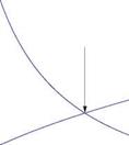
Le Balleur [18] studied the stability of the coupling procedures using harmonic analysis for both subsonic and supersonic flows, with attached and separated bound­ary layers and introduced a new semi-inverse iterative method for steady and unsteady transonic airfoils with shocks. To put his work in perspective, comparisons among the available methods and their limitations are useful. The standard direct method, dis­cussed before, does not converge for separated flows in general. Following Catherall and Mangler [24], the inverse methods have been used by many researchers. How­ever, such methods may not converge for attached flows. Figure 9.6 depicts the inverse and direct coupling procedures.

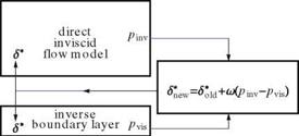
In a fully inverse method, the boundary layer equations are solved with a given displacement thickness and the outer edge velocity is calculated and fed to the inviscid flow calculations. To avoid the difficulties of both methods, Carter [25] introduced a semi-inverse method. In this method, starting with a displacement thickness both a direct inviscid flow calculation and an inverse viscous flow calculation are performed separately, then a correction formula, based on the difference on the inviscid surface pressure and the viscous pressure at the edge of the boundary layer, is used to update S*, seeFig.9.7.

At convergence, pi and pv are the same.

Le Balleur pointed out the limitations of Carter’s method and proposed an impor­tant modification based on his harmonic analysis, namely the correction formula is changed to

Подпись: dpv , for M < 1 dx d2 pv !&)' forM >1 Подпись: dpi dx d 2 pi dx2 Подпись:S*ew = S0id + fi Stew = S*oU + f2

Underrelaxation of S* is used to guarantee convergence for all cases. Before we discuss the Fourier analysis and stability of the coupling methods, two other methods are outlined. Brune et al. [26] introduced the fully simultaneous method which is shown in Fig. 9.8.

The potential flow calculations should provide the relation

Подпись: (9.78)up = up (S p)

Fig. 9.6 Coupling procedures: a inverse method; b direct method


Coupling Euler Calculations with Boundary Layer Integral Momentum Equations

Fig. 9.7 Semi-inverse method


far field

Coupling Euler Calculations with Boundary Layer Integral Momentum Equations

solid surface


Coupling Euler Calculations with Boundary Layer Integral Momentum Equations

matching

point


inviscid potential flow u p=u p (S p)

boundary layer Ss=Ss(u b)


u


Coupling Euler Calculations with Boundary Layer Integral Momentum Equations

Fig. 9.8 Brune et al. [26] coupling procedure while the boundary layer calculation gives

SB = SB (u в) (9.79)

The matching conditions are

Sp = SB and uP = uB (9.80)

In general, the potential equations are non linear. Upon linearization around an initial guess, the change of uP, AuP, can be obtained in terms of change of Sp, ASp, through an influence matrix, A P

Au P = AP ASP (9.81)

Similarly, the perturbed boundary layer equations gives

Au B = AB AS’B (9.82)

A first approximation to the matching conditions is

SP + ASP = SB + ASB (9.83)

The above four relations are solved simultaneously to obtain the corrections to uP and SB and the process is continued until convergence.

To simplify the above procedure, Veldman [27] introduced the Quasi-simultaneous method as in the following Fig. 9.9.

Veldman demonstrated the advantage of his procedure in a series of papers. Cebeci [28] also used similar procedures. Careful treatment is necessary for the case of tran­sonic flows, since the linearized inviscid flow equations are of mixed type. Ignoring this feature, as in some published works, may lead into problems. A comprehensive review is published in Ref. [30].

Подпись: v= Подпись: n

The following quasi-simultaneous coupling method has been successfully used by Wigton and Holt [29] for transonic flows Fig. 9.10.

Coupling the Numerical Solution of the Partial Differential Equations of the Inviscid Flow with Integral Equations of Boundary Layers

9.1.2.1 Inviscid Potential Flow Field Calculations and Integral Momentum Equations of Boundary Layer

For small disturbance potential flows, the nonlinear governing equation is given by the conservation form

d F д2ф dx + dy2

Подпись: F = (1 Coupling the Numerical Solution of the Partial Differential Equations of the Inviscid Flow with Integral Equations of Boundary Layers Coupling the Numerical Solution of the Partial Differential Equations of the Inviscid Flow with Integral Equations of Boundary Layers Подпись: (9.41)

where

This equation is valid for transonic flows with shocks as well as pure sub – and super-sonic flows, including the incompressible case (M0 = 0).

Coupling the Numerical Solution of the Partial Differential Equations of the Inviscid Flow with Integral Equations of Boundary Layers Coupling the Numerical Solution of the Partial Differential Equations of the Inviscid Flow with Integral Equations of Boundary Layers Подпись: (9.42)

The body is augmented with the displacement thickness and the boundary condi­tion becomes, for the upper surface

Coupling the Numerical Solution of the Partial Differential Equations of the Inviscid Flow with Integral Equations of Boundary Layers Подпись: (9.43)

Together with the integral momentum equation, the discrete equations can be solved using standard relaxation methods. To help the convergence, artificial time and viscosity terms are added in terms of the displacement thickness

The parameters a and e may be chosen guided by numerical analysis. Horizontal line relaxation with block pentadiagonal solver for the potential and S* at the lines above and below the airfoil (at у = 0), will allow tighter coupling for the case of boundary layer separation.

Moses et al. [17], solved the integral momentum equation and the integral mechan­ical energy equation simultaneously with the inviscid potential flow equation to sim­ulate separated flow in a diffuser.

Подпись: u ue Подпись: f (S'в) Подпись: (9.44)

In their work, the velocity profile is assumed to be a function of two parameters

where S is the thickness of the boundary layer and в is a profile shape parameter.

The integral equations can be written as a system of two ordinary differential equations

Подпись:d S d в due

an + a2 = bn + b2

dx dx dx

d S d в due

a21 + a22 = bt2 + b22 (9.46)

dx dx dx

For attached flows, with a given velocity ue, these two equations can be solved numerically with a stepwise procedure in the downstream direction.

For separated flows, the equations are singular at the separation point; the determi­nant of the coefficient matrix, A = (at, j), is zero. Solutions exist only for a specific

pressure gradient and in this case, the solution is not unique. Moreover, the calcula­tion is unstable for reverse flows. To avoid the difficulties associated with separation, the edge velocity, ue, is treated as unknown and the discrete inviscid equations are solved, augmented with the two equations for S and в, using vertical line relaxation, sweeping in the main flow direction.

Moses et al. [17] represented the inviscid flow in terms of stream function, hence the governing equation is

V2 ф = 0 (9.47)

and the boundary condition is

ф = const. (9.48)

on the displaced wall, say on the upper surface, y = yu+S*. The coupling between the inviscid flow and the boundary layer is imposed through the relation at the displaced wall

To start the calculations, quasi-one dimensional problem is solved to provide a good initial guess. The development of boundary layer through separation and attachment is successfully simulated and the edge velocity, ue, the displacement thickness, S*, and the skin friction coefficient, Cf, are accurately calculated.

Analysis of Incompressible Flows over Thin Airfoils Using Integral Momentum Equation for Boundary Layer

Consider thin symmetric airfoil (at zero angle of attack). The perturbation velocity of the inviscid flow can be approximated by:

U fc y'(Q

u(x, 0) = di (9.37)

n 0 x – i

where y(x) is the equation of the upper surface of the profile.

To account for the viscous effects, the shape of the airfoil is augmented by the displacement thickness as y(x) + 6*(x).

The integral momentum equation can be solved coupled with the above integral where ui = U + u.

To account for the wake, an integral from the trailing edge to the far field is added to the above formula, namely

uw(x, 0) = – di (9.38)

n 0 x – І

The velocity profile in the wake must satisfy a different boundary condition at y = 0, x > c, namely du/dy = 0, rather than u = 0.

The extension to linearized subsonic flows is straightforward. The Prandtl/Glauert transformation can be used to modify the inviscid velocity distribution together with Oswatitsch’s modification of Pohlhausen method for compressible boundary layer as discussed before.

The finite plate at zero angle of attack is a special case, where y(x) = 0.

For thin airfoils at angle of attack, the viscous layers on the top and the bottom are different. Moreover, the inviscid flow analysis requires solution of an integral equation, not just an evaluation of an integral as in the symmetric case.

9.1.1.2 Analysis of Supersonic Flows over Thin Airfoils Using Integral Momentum Equation for Boundary Layer

Again, the body is augmented with the displacement thickness and the Oswatitsch method may be used to solve the integral momentum equation for the compressible boundary layer. The inviscid flow solution, using d’Alembert formula (according to Ackeret thin airfoil theory), is given by:

, U,, U,

u(x, 0+) = –(f + (x) – a), u(x, О-) = -(f ~(x) – a) (9.39)

P P

where в = MO – 1 and a is the incidence.

For attached supersonic flows, the solution is obtained with a marching scheme in the x-direction, in one sweep. Iteration are still needed at each step. The case of angle of attack can be easily treated by splitting the top and bottom regions, since there is no interaction between the two.

Coupling Integral Formulations of both Inviscid and Viscous Flow Regions

9.1.1.1 Analysis of Internal Flows in Variable Area Ducts

The governing equations for the quasi-one dimensional flows in the inviscid core are

given by the conservation laws, assuming perfect gas:

Coupling Integral Formulations of both Inviscid and Viscous Flow Regions Подпись: (9.7)

continuity

Подпись: momentum
Подпись: dpuA d(pu2 + p) A dA dt + dx ^ dx

energy

dpEA dpuHA

ПГ + JLaXT =0 (9.9)

where H = E + р/р = yp/(y — 1)p + u2/2.

H = CpT is the total enthalpy, E = CvT the total internal energy, T the total temperature and A(x) denotes the effective cross-sectional area. The average inviscid velocity in the slowly varying area duct, u, denotes also the velocity ui at the edge of the boundary layer.

The above equations can be solved with artificial viscosity or using upwind schemes. For the latter, see Chattot [2].

For the steady case, the time dependent terms vanish and the continuity and energy equations reduce to the integrals of motion in terms of the algebraic relations:

pu A = m = const. (9.10)

2

Y P u

+ = H = const. (9.11)

Y — 1 P 2

The momentum equation can be rewritten in one variable, say u (or p) by elim­inating the other two variables using the two algebraic relations. Again, artificial viscosity or upwind scheme can be used for this nonlinear scalar ordinary differen­tial equation, see Hafez et al. [3].

Coupling Integral Formulations of both Inviscid and Viscous Flow Regions Подпись: (9.12)

On the other hand, the von Karman integral momentum equation for the steady compressible boundary layer is given by:

where

n = 0 for planar flow n = 1 for axisymmetric flow

In the above equation, S* is the displacement thickness, and в is the momentum thickness, while Cf is the skin friction coefficient.

A special case is the incompressible flow through a channel of width b, where p is constant and the effective area is simply A(x) = Ageo(x) — 2bS*(x).

Подпись: u(x) = ui (x) Подпись: C Ageo (x) — 2b6* (x) Подпись: (9.13)

where Ageo is the geometric area. Moreover, uA = mIp = C = const., hence

The problem thus reduces to solving the integral momentum equation. There are however three variables in this equation: 6*, в and Cf. Following Pohlhausen’s approximate method, a form of the velocity profile in the boundary layer is assumed, where

u y

= f (n) and n = (9.14)

ui 6(x)

where 6(x) is the total thickness of the boundary layer and y is the distance from the duct wall. The function f should satisfy some boundary conditions on u:

d2u

ui

dui

d 3ui

at y = 0, u = 0,

dy2

v

dx

dx3

= 0,…

(9.15)

du

d 2u

as y ^ ж, u ^ ui,

dy

0,

dy2

0

(9.16)

The conditions at infinity are only approached asymptotically. These conditions will be applied at y = 6 instead.

The conditions on f (n) become:

Подпись:Подпись: (9.19)f (0) = 0, f" (0) = —Л, f(0) = 0,… f (1) = 1, f ‘(1) = f "(1) = f ‘"(1) = 0

where

62 dui v dx

From the assumed velocity profile, 6*, в and Cf are related to 6 as follows:

* = 6 / V — f )dn

0

(9.20)

= 6 ( f — f2)dn 0

(9.21)

2v

Cf = f ‘(0) ui 6

(9.22)

Pohlhausen used a fourth order polynomial for f (n), satisfying five conditions, two at y = 0 and three at y = S. Hence

U 3 4 1 3

– = f (n) = 2n – 2n3 + n + 7Лп(1 – n) (9.23)

Ui 6

With this form, the following relations can be obtained:

S* 3 Л в 1 / 37 Л Л3 Cf ui S Л

— =————— , – = , = 4 + – (9.24)

S 10 120 S 63 5 15 144 2^ 3

Thus, a nonlinear ordinary differential equation in Л must be solved numerically. A step by step technique can be used in a standard way.

Obviously, other forms of the velocity profile can be chosen. Variations of Pohlhausen method are available in the literature. Notably is Thwaites’ method which is based on an empirical relation to simplify the algebra.

Methods based on two equations, integral momentum equation and integral mechanical energy equation, are known to produce more accurate results. In particu­lar, a family of profiles with two parameters are introduced in the work of Wieghardt [4], see also Walz [5], Truckenbrodt [6] and Tani [7].

In their work, the mechanical energy equation is derived by multiplying the momentum equation by U and upon integration across the boundary layer, an integral relation is obtained in terms of a mechanical energy thickness.

Coupling Integral Formulations of both Inviscid and Viscous Flow Regions Подпись: (9.25)
Coupling Integral Formulations of both Inviscid and Viscous Flow Regions

The final results for incompressible flow is

where

Coupling Integral Formulations of both Inviscid and Viscous Flow Regions(9.26)

Alternatively, Listsianski and Dorodnitsyn used their method of integral relations, where the boundary layer is divided into strips and approximates are obtained via weighted averaging over each strip. For more details see Holt [8].

In this regard, one should mention that over the last century, boundary layer equations have been solved by the methods of weighted residuals, including the method of collocation, the method of moments and the Galerkin method. See for example Schlichting [9], Rosenhead [10].

For compressible flows, an integral based on the total energy equation is used, see Ref. [11].

Following Stewartson [11], a total temperature is defined as:

u2

T = t + (9.27)

2Cp

where t represents the static temperature. In terms of the total temperature, the energy equation reads:

d T d T

+ "" sy


d fi d dy _ Pr dy


(9.28)


T +


Coupling Integral Formulations of both Inviscid and Viscous Flow Regions

Upon integration w. r.t. y, one obtains

d

pu (T – Ti) dy

dx 0


i d T Pr dy ly=0


(9.29)


where

ui

T, = ti + b (9.30)

2Cp

Pr is the Prandtl number. If the wall is insulated (i. e. dT/dy = 0 at y = 0), the equation is integrated to give (see [12])

pu (T – Ti) dy = const. (9.31)

For the special case, Pr = 1, Crocco and Busemann noticed independently, that T = const. The total temperature is thus constant everywhere across the boundary layer and the wall temperature is given by:

Coupling Integral Formulations of both Inviscid and Viscous Flow Regions

(9.32)


In general, the total energy thickness is defined as:

Coupling Integral Formulations of both Inviscid and Viscous Flow Regions(9.33)

The integral mechanical energy equation becomes:

d C qw

dx pi ui Ti

where qw is the heat flux through the wall

qw = k |y=0 (9.35)

dy

Gruschwitz [13] introduced a method similar to that of Pohlhausen to calculate compressible flows with arbitrary Prandtl numbers, using both the momentum and total energy integral equations and in this case a temperature profile is assumed satisfying the temperature boundary conditions.

Подпись: Pi_ P Coupling Integral Formulations of both Inviscid and Viscous Flow Regions Подпись: (9.36)

On the other hand, Oswatitsch [14] developed a simpler method assuming Pr = 1. Since the pressure is constant across the boundary layer, one can show that, see [15]

Hence, only the momentum integral equation for compressible flow with a quartic polynomial for the velocity in terms of Л, may be used, where the density and the temperature distributions are related to the velocity profile.

The above development is for steady laminar flows. For steady and unsteady compressible turbulent flows, the reader is referred to [16], where several empirical formulae are employed.

Viscous/Inviscid Interaction Procedures Based on Displacement Thickness Concept

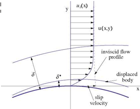
Consider steady 2-D flows. For high Reynolds numbers, an inviscid model can be used everywhere except in a thin viscous layer over the body and in its wake. The latter is needed since the inviscid flow theory allows a slip velocity at the solid surface and the physical “no slip” boundary condition can not be imposed, in general.

If the thin viscous layer is not introduced, the inviscid flow profile, extended to the wall, will have more mass flow rate than the corresponding viscous flow profile as shown in the figure, see Fig. 9.3.

© Springer Science+Business Media Dordrecht 2015

J. J. Chattot and M. M. Hafez, Theoretical and Applied Aerodynamics,

DOI 10.1007/978-94-017-9825-9_9

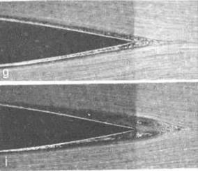
Fig. 9.1 Hydrodynamic visualization, courtesy H. Werle ONERA—the French Aerospace Lab, ONERA RA 1987-3


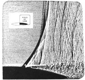
Fig. 9.2 Shock-induced separation, M = 0.785, Re = 107, from McDevitt Ref. [1]


Viscous/Inviscid Interaction Procedures Based on Displacement Thickness ConceptViscous/Inviscid Interaction Procedures Based on Displacement Thickness Concept

It is assumed that the viscous stress contributions are negligible outside the thin layer of thickness S, compared to the pressure and inertia forces.

Подпись: pu Pi ut.
Viscous/Inviscid Interaction Procedures Based on Displacement Thickness Concept

As discussed before in the previous chapter on boundary layers, Prandtl introduced the concept of displacement thickness, where the body is displaced such that the inviscid flow profile over the displaced body will have the same mass flow rate as the viscous flow profile over the original body. The equation for such a displacement thickness S*, is given by

Подпись: far field

Viscous/Inviscid Interaction Procedures Based on Displacement Thickness Concept

Fig. 9.4 Viscous/inviscid interaction

For incompressible flows, p = pi = const. Notice also, both 6 and 6* are chang­ing from one station to another, in general. However, for a self-similar solution of boundary layer over a flat plate without pressure gradient, u/ui is a function of П = y/S only, hence the ratio 6*/6 becomes a constant. In the non similar case, ui changes in the streamwise direction as well.

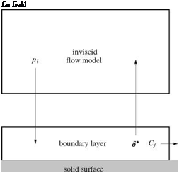
Now the viscous/inviscid interaction can be described by the following diagram. See Fig. 9.4.

The boundary layer and inviscid flow calculations are coupled. Boundary layer codes require the inviscid surface pressure distributions from the inviscid flow codes,

while the inviscid flow calculations are performed over the displaced body (and wake). In general, the two calculations must be performed simultaneously.

For some cases, mainly attached flows, the interaction is weak, and the two cal­culations are decoupled and the final results are obtained via iterations. To start the procedure, 6*(x) is assumed known (for example through ignoring the pressure gra­dient) and the cycle is started until convergence. This is not always the case. A limit cycle may occur and hence the results are not satisfactory. The convergence problems are critical for the viscous effects to be properly accounted for.

The feedback of the boundary layer to the inviscid flow can be imposed through a transpiration boundary condition to avoid changing the grid in the inviscid flow calculations from iteration to iteration. Using small disturbance formulation, the same grid is used for all iterations. Instead of imposing the no penetration boundary condition on the displaced body (i. e. the inviscid flow is tangent to the displaced body), an equivalent condition on the original body is derived using the Taylor series expansion as follows.

Integrating across the boundary layer and using the Leibnitz rule, one gets in terms of local coordinates (x, y):

dpu Sdpv

d У + d У = 0 dx 0 dy

(9.2)

dS

pu dy – pi u – + pi v – = 0 d x

(9.3)

d

dx

S

0

s

0

The definition of displacement thickness can be written

s

Подпись: (9.4)pu dy = piui (S – S*)

0

after substitution, the equation now reads

Подпись:Подпись: (9.5)dx dx

A Taylor expansion of (pV) provides the transpiration mass flux to first order as

(pv)0 = (pv)i – S i – + O (S2) = pi Vi + S – – + O (S2) ~ (piui S*)

dy dx dx

(9.6)

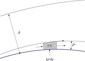
Hence, if a flux (pv)0 is blown at the original surface given by the above equation, the inviscid flow will be tangent to the displaced body.

Подпись: Fig. 9.5 Control volume for application of transpiration boundary condition
Viscous/Inviscid Interaction Procedures Based on Displacement Thickness Concept

The above statement is a consequence of conservation of mass for the inviscid flow applied to the control volume shown in Fig. 9.5. In the above argument, the variation of ptut across the boundary layer is ignored.

In the following, four formulations are considered:

(1) Coupling integral formulations of both inviscid and viscous flow regions.

(2) Coupling the numerical solution of the partial differential equations of the invis­cid flow with integral equations of boundary layers.

(3) Coupling the numerical solution of the partial differential equations of the vis­cous flow with the integral equations of the outer inviscid flows.

(4) Coupling numerical solutions of partial differential equations of both the inviscid and viscous flow regions.

After these four formulations are covered, other approaches based on domain decom­position will be addressed in latter part of this chapter.

Viscous/Inviscid Interaction Procedures

In the previous chapters, small disturbance potential flow theories for 2-D and 3-D, incompressible and compressible, steady and unsteady flows over aerodynamic configurations are studied. The main results are the surface pressure distributions and the associated lift and “inviscid” drag coefficients. Also, boundary layer theory for the corresponding flows is discussed and the main result is the prediction of the skin friction drag, assuming the surface pressure distributions are known from the inviscid calculations (Fig.9.1).

The feedback effects of boundary layers on the inviscid flows can be represented through the displacement thickness. This concept, for both laminar and turbulent flows, allows uncoupled calculations at least for the cases with no separation. The mutual strong interaction between the thin viscous layer over the body and in the wake, for high Reynolds numbers, and the main inviscid flow is the subject of this chapter. Beside the displacement thickness methods, other approaches based on domain decomposition techniques will be discussed as well. A challenging prob­lem pertinent to this chapter concerns the shock wave/boundary layer interaction, an example of which is shown in Fig. 9.2 for an 18% thick biconvex circular arc airfoil, from [1].

Summary of Chapter 8

This chapter starts with a discussion of vorticity versus strain rate, the derivation of viscous stresses and of theNavier-Stokes equations for 2-D incompressible flows, fol­lowed by Prandtl boundary layer theory including numerical solution for the bound­ary layer over a flat plate and calculations of boundary layers displacement and momentum thicknesses.

Next, compressible viscous flows are considered and the corresponding Navier – Stokes and boundary layer equations are derived. Determination of drag is also discussed.

Historical and classical works of Blasius solution for a flat plate and Falkner – Skan solution for flow past a wedge, as well as the von Karman Integral Momentum equation (with streamwise pressure gradient) and transformation of boundary layer equations (due to von Mises and also Howarth and Dorodnitcyn) are considered together with comments on flow separation, flow at the trailing edges and three­dimensional boundary layers.

Turbulent boundary layers are not covered in this book.

1.4 Problems

8.5.1

Consider the stream function in the upper half plane

1 3 1 2

ф(л, y) = – y – mxy, y > 0 6 2

where m > 0 is a fixed parameter.

Find the shape and make a sketch of the streamlines of this flow. Some remarkable streamlines correspond to ф = 0. Show that y = 0 could be a solid wall.

Calculate the velocity components (u, v) and show, with arrows, the direction of the flow. Indicate with dots, the location of flow reversal line, u = 0.

Calculate the vorticity w = dv/дx – du/дy and indicate with dotted line the location w = 0.

Calculate the wall shear stress rw(x).

Sketch some velocity profiles u (x, y) atthreefixed x-locations, x = -0.5, x = 0 and x = 0.5.

Why is this not a real viscous flow solution (Hint: look for a pressure field).

References

1. Oswatitsch, K.: Gas Dynamics. Academic Press, New York (1956)

2. Liepmann, H., Roshko, A.: Elements of Gas Dynamics. Wiley, New York (1957)

3. Schlichting, H.: Boundary Layer Theory. McGraw Hill, New York (1979)

4. Howarth, L.: Laminar boundary layers. Fluid Dynamics I. Encyclopedia of Physics, vol. VIII/I. Springer, Berlin (1959)

5. Meier, G. E., et al. (eds.): IUTAM Symposium on One Hundred Years of Boundary Layer Research. Springer, New York (2004)

6. Stewartson, K.: The Theory of Laminar Boundary Layers in Compressible Fluids. Oxford University Press, Oxford (1964)

7. Batchelor, G. K.: An Introduction to Fluid Dynamics. Cambridge University Press, New York (1967)

8. Rosenhead, L. (ed.): Laminar Boundary Layers. Oxford University Press, Oxford (1963)

9. White, F. M.: Viscous Fluid Flow. McGraw Hill, New York (1974)

10. Moran, J.: Theoretical and Computational Aerodynamics. Wiley, New York (1984)