Our heavyweight helicopter equal in the world does not have
In Rostov started production of the most load-lifting rotary-wing car The Russian holding «Helicopt[...]

Everything about aircrafts and helicopters. News and events in aviation worldwide. Civil, transportation, military helicopters and airplanes.

Everything about aircrafts and helicopters. News and events in aviation worldwide. Civil, transportation, military helicopters and airplanes.

Everything about aircrafts and helicopters. News and events in aviation worldwide. Civil, transportation, military helicopters and airplanes.

Everything about aircrafts and helicopters. News and events in aviation worldwide. Civil, transportation, military helicopters and airplanes.


The low natural frequency of the pressure gages described so far has limited their use to essentially steady pressures. Although the pressures to be measured in many experiments are substantially steady, there are cases, as in the study of turbulent or separated flows, of flutter or in tests carried in a shock tube, where it is essential to measure unsteady pressures.
To meet these requirements pressure transducers that convert a pressure signal into an electrical signal are required. In fact, transducers can do the following:
■ can be built having high resonant frequencies;
■ can be miniaturized and thus can be installed adjacent to or even within the model to be tested, thus reducing the delays due to the transmission of pressure signals in pipes.
Transducers greatly simplify the procedure for getting and recording data since the electrical signal from the transducer can be digitized and sent to a computer. This characteristic has led in time to the adoption of transducers even when pressure is steady, especially when many pressure measurements are needed.
Hydrostatic manometers become impractical if pressures higher than 3 atmospheres have to be measured because, even if mercury is used, the column length exceeds 2 meters. On the other hand, hydrostatic manometers are fragile, are not portable and are therefore only suitable for laboratory applications. In an industrial environment, manometers are therefore used in which the difference in pressure causes the deformation of an elastic element.
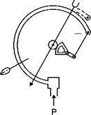
In the Bourdon gage (Figure 1.6), the sensor is a tube with a flattened section closed at one end and bent as an arc of a circle. The pressure to be measured, applied inside the tube, tends to straighten it, the closed end is free to move and its deflection is communicated through a rack – and-pinion or helical-cam mechanism to a pointer that moves on a graduated scale which is obtained through factory calibration. The range of this type of gage extends from about 1/30 to hundreds of atmospheres.
In the aneroid (or diaphragm) manometer (Figure 1.7) the sensor is a capsule covered with a thin metal diaphragm with concentric corrugations that make it easily deformable. These gages are reliable for accurate indication of differentials as low as 2 mm of water. Such a mechanism is commonly employed in recording pressure indicators and in barometers.
Both the tubular elements and the diaphragm are temperature sensitive and therefore require further calibration in the laboratory when used at temperatures different from the standard.
![]()
 |
Bourdon gage
![]()
 |
Diaphragm gage
Many pressures can be measured simultaneously with a multi-tube manometer (Figure 1.5), having one or more dozens of tubes connected to a common tray connected to a reservoir open to the reference pressure. For convenience, the reference pressure is also applied to one tube (or rather to the two extreme tubes of the manometer) to allow zero adjust-ment. Tubes are laid side by side on a solid table provided with a scale and covered by a sheet of protective glass or plastic that is usually also provided with a scale: the double scale serves to eliminate the error of parallax. The position of the reservoir is adjustable and sometimes the table can be rotated; the inclination of the table can be read on a circular scale.
![]()
|
|
||
|
|
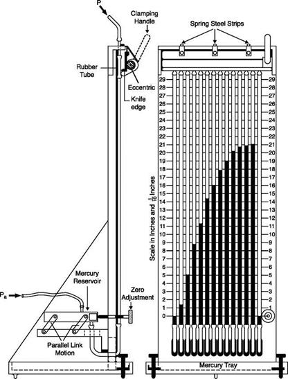
To reduce the test time, especially in intermittent wind tunnels, a means of freezing the readings of the many tubes is needed; an example can be seen in the side view of the multi-tube manometer of Figure 1.5: it consists of an eccentric placed at the top of the pipe manifolds which, when rotated, squeezes the rubber tubes, thereby blocking the pressure in them. Alternatively, results can be frozen with a camera.
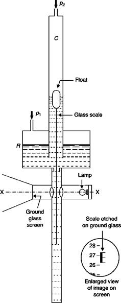
A hydrostatic manometer that is easier to be read, if not more accurate, is the projection or Betz manometer. The operating principle is illustrated in Figure 1.4. The difference in level between the liquid in the cylinder C and the reservoir R is indicated by a scale suspended to a float. The scale directly shows the difference in level (the decrease in the level of R is accounted for in the calibration of the scale).
An enlarged image of the scale located on the plane XX is projected onto a frosted glass on which a reference line is marked. The scale can be engraved in order to show centimeters of difference in level; the fractions of a centimeter can be appreciated by comparison with a scale etched on the frosted glass.
The Betz manometer was used primarily to control the operating speed of a wind tunnel: the large internal volume makes it too slow for the measurement of unsteady pressures, as in turbulent boundary layers, and the quite high cost does not permit the use of many Betz manometers each connected to a pressure tap.
The sensitivity of a hydrostatic manometer can be extended by a factor of 10 using an inclined tube manometer (Figure 1.3) while preserving the simplicity and robustness of the single tube manometer.
Assuming that the change of level in the reservoir is negligible and that the effects of surface tension can be ignored, for an inclined tube manometer:
A – p =PgLsena (1.9)
 |
where L is the length of liquid column above zero, and a is the inclination of the tube with respect to the horizontal. The sensitivity of the manometer increases with decreasing inclination, a; the use of angles below 5° with the horizontal brings problems due to surface tension even if alcohol
is used, because the meniscus becomes too stretched, and also the perfection of the glass tubes to the degree of precision required cannot be guaranteed.
Unfortunately, a manometer of this type must be calibrated because errors can arise due to a slight curvature of the tube or to the effects of surface tension caused by the small non-uniformity of the internal diameter.
The U-gage requires the reading of two levels since it is not advisable to measure the displacement of one meniscus from zero, assuming that this is half the difference in height, unless the inside diameter of the tube is perfectly constant.
This difficulty can be avoided by building the manometer with one arm (reservoir) with an area many times the area of the other one (Figure 1.2):
![]()
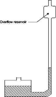 |
Single tube manometer
in this way, it is sufficient to read the level in the narrow tube, the change in level in the reservoir being negligible. On the other hand, the height of the reservoir can be adjusted in order to adjust the zero of the scale before making the reading. However, the single-tube manometer requires the taps to be switched to change from positive to negative differentials while either can be read without tap changes on the U-tube instrument.
Since the internal diameters of the two arms in this case are very different, strictly speaking, the reading should be corrected for the different effects of surface tension in the two arms. Since the magnitude of the correction depends very much on the cleanliness of the tube manometer (the presence of grease in particular has a significant effect), it would be better to reduce the effects of surface tension by adopting a pipe diameter that is not too small.
The manometer will not immediately sense pressure changes because a flow has to be generated in the pipe connecting the measuring point and the manometer to compensate for the change in density of the gas inside the tube and the manometer as well for the displacement of the manometer liquid (the first cause of delay is negligible in measurements performed in liquids).
If there is a sudden change in pressure, ±dp, a very slow viscous flow (the Poiseuille flow) is generated in the tube connecting the pressure tap to the manometer; the average speed in the section is proportional to the pressure difference between the tap and the manometer:

![]() – 1
– 1
V= — V
2 max
where m is the dynamic viscosity of air, and £ and d are the length and the diameter of the tube.
The air flow rate passing through the tube produces a change in the mass in the manometer due to both a change in density and a variation in the volume available (Vol) caused by the displacement of the liquid:
Since the displacement of the liquid surface in the tube connected to the tap is half of Ah, by using Equation (1.1), is it obtained:
dVol = Adh = Ad{Ah = A dp dt dt 2dt 2g p£ dt
where A is the area of the section of the manometer tube. In isothermal conditions, the change in density is related to the change in pressure [5]:
![]() dp _ p dp dt p dt
dp _ p dp dt p dt
Substituting Equations (1.3), (1.5) and (1.6) into Equation (1.4) yields [5]:
![]() pn – put d = A + Vol I d
pn – put d = A + Vol I d
128p£ ^ 2gp£ p J dt
The pressure in the manometer varies with speed decreasing gradually as the pressure difference between inlet and manometer decreases, therefore the manometer adapts only asymptotically to the new pressure, p + dp.
We define the time constant, t*, as the time the manometer would take to adapt to the change in pressure dp if the rate of change of pressure
were maintained equal to the initial value obtained by putting Pin – pout = dp in Equation (1.7):
Sp 128 pi f A Vol ^
T* = dp/dt = ndA [2g + ~J (1.8)
For normal-sized gages the time constant varies from 1 to 10 ms (frequency range 0.1 – r – 1 kHz). For this reason, and the difficulty of registering pressure fluctuations by hand, no hydrostatic manometers are suitable for unsteady pressure measurements.
With a U-shaped vertical manometer, in order to limit the reading error to less than 2%, differences in heights less than 50 mm cannot be measured since the accuracy of the naked eye in reading the height of liquid in each tube is limited to 0.5 mm; the presence of the meniscus does not recommend the use of systems of magnification. On the other hand it is impractical to build manometers with arms longer than 5 or 6 meters.
The minimum and maximum differential pressures measurable by U-tube manometers using water or mercury can therefore be calculated approximately, using Equation (1.1):
Water Apmm = 0.5 [kPa] Ap^ = 60 [kPa]
Mercury Apmin = 6.6 [kPa] Apmax = 810 [kPa]
For low pressure, alcohol is preferred to water because it has a surface tension which is 30% that of water and the meniscus is negligible, but its density must be controlled because it changes rapidly since it absorbs moisture from the environment. The other liquids listed in Table
1.1 and having an intermediate density are corrosive and used more rarely.
In this kind of manometer, the difference between two pressures is balanced by the difference of level in a liquid. To measure pressure in a liquid, a manometer can use the working fluid itself, this is obviously not the case when pressure is measured in a gas: the choice of the manometer fluid (or separating liquid) will be affected by the pressure field, the required sensitivity and the physical and chemical properties of the liquid. The properties of the most common manometer liquids are shown in
Table 1.1.
The liquids that work best are those that are chemically stable, are not affected by moisture and have the following qualities: low viscosity, as this reduces the response time; low surface tension, low volumetric expansion coefficient, low volatility, consistency, and resistance to contamination.
1.2.1 The U-tube manometer
The fluid is contained in a glass tube with U-shaped vertical arms (Figure 1.1) with internal diameters more or less constant. The pressures pj and p2 will be applied through suitable piping connection to the two arms of the manometer. If the difference between the heights of the columns of fluid in the two arms is Ah, it will be:
Л – p = p – Pa)gAh = PgAh (1.1)
where g is the acceleration of gravity and pt and pa are the densities of the manometer liquid and of air, respectively. The approximation made when
|
Liquid |
Density at 15°C (g/ml) |
Surface tension (dynes/cm) |
Angle of contact |
Coefficient of cubical expansion per С x 105 |
Remarks |
|
Water |
0.999 |
74 |
8°(*) |
5°C – 10°C 5.3 10°C – 20°С 15.0 |
(*) 0° if the glass is quite clean. Surface tension may be lowered by adding wetting agent. Corrodes iron and steel |
|
Ethyl alcohol C2H5OH |
0.8 <**> |
22 |
110 |
(**) Rises if water is present Corrodes iron and steel |
|
|
Ethylene bromide, C2H4Br3 |
2.18 |
38 |
High |
Attacks natural and synthetic rubber, corrodes iron and steel. Surface tension can be reduced by adding toluol. |
|
|
Acetylene tetrabromide C2H2Br4 |
2.98-3.00 |
Attacks natural and synthetic rubber, corrodes iron and steel. Surface tension may be reduced by adding toluol |
|||
|
Mercury Hg |
13.56 |
465 |
127° |
18 |
Combines with gold, copper and brass. Attacks iron and steel very slowly |
|
Carbon tetrachloride CCI4 |
1.58 |
26 |
0° |
124 |
Attacks rubber, but not metals |

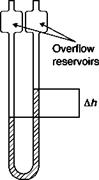 |
U-tube manometer Pi 02
pa is considered negligible with respect to pt is of the order 10-3 when water is the manometer liquid and 10-4 when mercury is used.
Usually one of the two arms of the manometer remains connected to the environment; in wind tunnels, sometimes it is connected to the static pressure of the stream, pm, so the manometer indicates the value of p – pm which actually determines the forces acting on the body: in fact, pm is the hydrostatic pressure acting all around the body, thus giving a net zero contribution.
The manometer is susceptible to blowing its liquid into the attached pressure lines if the range of the instrument is exceeded; however, all good manometers employ overflow reservoirs at the end of the tubes to retain the fluid in case of accidental overloading.
This type of manometer is very simple and requires no calibration because pressure is obtained from the analytical Equation (1.1). Furthermore, if the internal diameters of the two arms are equal, the effects of capillarity are balanced, though small errors can arise due to the fact that the tube wall next to the liquid surface is wet in the arm in which the level decreases and is dry in the other one. Errors like these can be eliminated by raising beyond the equilibrium position the column of liquid that must rise and letting it fall back into position before taking the reading.
The only adjustments necessary are those for changes from their standard values of the density of the liquid and of the length of the scale due to changes in temperature. If the level difference measured at temperature T is AhT and the scale is properly calibrated to the temperature T0, the corrected height difference, Ah, is given by:
where a[U_1] is the coefficient of linear expansion of the material of the scale and 5[U_1] is the coefficient of volumetric expansion of the manometer liquid. Under normal conditions the temperature changes are not large enough to introduce appreciable errors if the density and the calibration of the scale are referred to the standard temperature of 15°C.
Abstract: This chapter highlights pressure sensors ranging from the classical manometers, based on the displacement of the surface of a liquid or on the deflection of the walls of a metallic chamber, to pressure transducers where the deflection of a disk or of a cantilever beam is converted into an electric signal eventually digitalized and sent to a computer. Only the basic principle of pressure-sensitive paints is reported as this technique is still a subject of research.
Key words: hydrostatic manometers, mechanical manometers, pressure transducers.
1.1 Fundamental features
Pressure measurements are essential in aerodynamics for the calculation of velocity, direction and mass flow rate of a fluid stream, and are complementary to balances in measuring the aerodynamic forces acting on a body.
Pressure sensors range from the classical hydrostatic and mechanical manometers to pressure transducers and to pressure-sensitive paints (PSP). The choice depends on the magnitude of the pressure to be measured, on its steadiness, on the required accuracy and resolution, and on the ease with which data can be handled and stored.
It is important to realize that all pressure sensors measure a differential pressure, either between two pressures associated with the flow or between a flow pressure and the atmospheric pressure. Thus, if pressure data are referenced to the contemporary atmosphere pressure (gage pressure sensors), it is imperative to measure this value enabling later reduction of the data to an absolute or other standard condition. Only if the reference is vacuum absolute values of pressure are obtained.
The main desirable characteristics in a pressure gage, whether they are
feasible or not, are given below. In practice, the best possible compromise
is needed to adapt the instrument to the specific case:
1. Range. The lowest pressure obtained with techniques for the vacuum are of the order of 10-14 atmospheres. At the other extreme, in the laboratory pressures greater than 105 atmospheres were obtained. The field is so vast that a particular type of manometer may cover only a small fraction of it.
2. Frequency response. In many applications the pressure changes so slowly that it can be considered constant. On the other hand, the jump in pressure that occurs through a shock wave propagating in a gas at rest can occur in a time less than 10-7 s. Fluctuating pressures that are generated in gas guns, engine cylinders, and in gas turbines have characteristic times that cover the whole field between the two above-mentioned extremes. Frequencies range therefore from 0 to 10 MHz (but no pressure sensor developed so far is able to approach this limit).
3. Accuracy. Usually the accuracy of pressure transducers is referred to the full scale, i. e. the maximum measurable pressure. It is clear that if the instrument is accurate within 1% of the full scale, the measurement of a pressure that is equal to one-tenth of the full scale will be affected by an error of 10%. Therefore, for good accuracy, an instrument should be chosen whose full scale is only slightly higher than the maximum pressure to be measured.
4. Sensitivity. All things being equal, a high sensitivity is always to be preferred: the output signal requires less amplification (pressure transducers) or allows a more precise reading (manometers).
5. Linearity. Usually it is considered convenient to have the output signal proportional to pressure, but this is not only not essential but in some cases not even desirable if the measurement range is very large.
6. Size. The boundaries of the system to be explored can limit the size of the sensor (for example, the need to measure pressure between turbine blades or the need to insert many sensors in a wing model); the size of the sensor may affect its interaction with the stream, disturbing the measurement; because the reading is only an average on the surface of the sensor, size limits the level of detail that can be detected.
7. Calibration. In some cases, the response of the sensor can be calculated by an analytical equation (e. g. hydrostatic manometers). For simple systems, the dynamic response can be inferred from the
static calibration; but in most cases only a dynamic calibration provides a sufficiently reliable basis from which the results can be interpreted.
8. Data acquisition and handling. The hydrostatic or metal manometers require manual reading and transcription of the data. Some types of transducers produce a frequency modulated signal that has to be read by a system of demodulation to obtain pressure. Obviously, the ease and certainty with which data can be interpreted and recorded are important factors in choosing a pressure sensor.