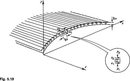
In Section 4.3, it was shown that the flow around a thin wing could be regarded as a superimposition of a circulatory and a non-circulatory flow. In a similar fashion the same can be established for the flow around a thin wing. For a wing to be classified as thin the following must hold:
• The maximum thickness-to-chord ratio, usually located at mid-span, must be much less than unity.
• The camber lines of all wing sections must only deviate slightly from the corresponding chord-line.
• The wing may be twisted but the angles of incidence of all wing sections must remain small and the rate of change of twist must be gradual.
• The rate of change of wing taper must be gradual.
These conditions would be met for most practical wings. If they are satisfied then the velocities at any point over the wing only differ by a small amount from that of the oncoming flow.
For the thin aerofoil the non-circulatory flow corresponds to that around a symmetrical aerofoil at zero incidence. Similarly for the thin wing it corresponds to that around an untwisted wing, having the same planform shape as the actual wing, but with symmetrical sections at zero angle of incidence. Like its two-dimensional counterpart in aerofoil theory this so-called displacement (or thickness) effect makes no contribution to the lifting characteristics of the wing. The circulatory flow – the so-called lifting effect – corresponds to that around an infinitely thin, cambered and possibly twisted, plate at an angle of attack. The plate takes the same planform shape as the mid-plane of the actual wing. This circulatory part of the flow is modelled by a vortex sheet. The lifting characteristics of the wing are determined solely by this component of the flow field. Consequently, the lifting effect is of much greater practical interest than the displacement effect. Accordingly much of this chapter will be devoted to the former. First, however, the displacement effect is briefly considered.
Displacement effect
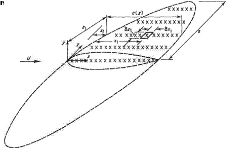
In Section 4.9, it was shown how the non-circulatory component of the flow around an aerofoil could be modelled by a distribution of sources and sinks along the chord line. Similarly, in the case of the wing, this component of the flow can be modelled by distributing sources and sinks over the entire mid-plane of the wing (Fig. 5.20). In much the same way as Eqn (4.103) was derived (referring to Fig. 5.20 for the geometric notation) it can be shown that the surface pressure coefficient at point (xi, yi) due to the thickness effect is given by
where x(z) denotes the leading edge of the wing.
In general, Eqn (5.23) is fairly cumbersome and nowadays modern computational techniques like the panel method (see Section 5.8) are used. In the special case of
wings having high aspect ratio, intuition would suggest that the flow over most of the wing behaves as if it were two-dimensional. Plainly this will not be a good approximation near the wing-tips where the formation of the trailing vortices leads to highly three-dimensional flow. However, away from the wing-tip region, Eqn (5.23) reduces approximately to Eqn (4.103) and, to a good approximation, the Cp distributions obtained for symmetrical aerofoils can be used for the wing sections. For completeness this result is demonstrated formally immediately below. However, if this is not of interest go directly to the next section.
Change the variables in Eqn (5.23) to x = (x – xi)/c, z = z/c and z — (z – z{)/c. Now provided that the non-dimensional shape of the wing-section does not change along the span, or, at any rate, only changes very slowly St = d(yjc)/dx does not vary with z and the integral I in Eqn (5.23) becomes
|
(s-Zi)/c dz
(**.)/« (x2+72f2
|

1 /•! r(s-2i)/c
h = – St(x)x —
CJ0 J~{s+z)/c [X‘

, 2 72~–2
Lifting effect
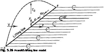
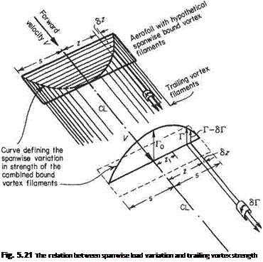
To understand the fundamental concepts involved in modelling the lifting effect of a vortex sheet, consider first the simple rectangular wing depicted in Fig. 5.21. Here the vortex sheet is constructed from a collection of horseshoe vortices located in the у = 0 plane.
From Helmholtz’s second theorem (Section 5.2.1) the strength of the circulation round any section of the vortex sheet (or wing) is the sum of the strengths of the
vortex filaments cut by the section plane. As the section plane is progressively moved outwards from the centre section to the tips, fewer and fewer bound vortex filaments are left for successive sections to cut so that the circulation around the sections diminishes. In this way, the spanwise change in circulation round the wing is related to the spanwise lengths of the bound vortices. Now, as the section plane is moved outwards along the bound bundle of filaments, and as the strength of the bundle decreases, the strength of the vortex filaments so far shed must increase, as the overall strength of the system cannot diminish. Thus the change in circulation from section to section is equal to the strength of the vorticity shed between these sections.
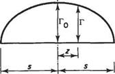
Figure 5.21 shows a simple rectangular wing shedding a vortex trail with each pair of trailing vortex filaments completed by a spanwise bound vortex. It will be noticed that a line joining the ends of all the spanwise vortices forms a curve that, assuming each vortex is of equal strength and given a suitable scale, would be a curve of the total strengths of the bound vortices at any section plotted against the span. This curve has been plotted for clarity on a spanwise line through the centre of pressure of the wing and is a plot of (chordwise) circulation (Г) measured on a vertical ordinate, against spanwise distance from the centre-line (CL) measured on the horizontal ordinate. Thus at a section z from the centre-line sufficient hypothetical bound vortices are cut to produce a chordwise circulation around that section equal to Г. At a further section z + Sz from the centre-line the circulation has fallen to Г — 6Г, indicating that between sections z and z + 6z trailing vorticity to the strength of i5T has been shed.
If the circulation curve can be described as some function of z, f(z) say then the strength of circulation shed
6Г = – Щ^-8г (5.25)
dz
Now at any section the lift per span is given by the Kutta-Zhukovsky theorem Eqn (4.10)
l = pVT
and for a given flight speed and air density, Г is thus proportional to /. But / is the local intensity of lift or lift grading, which is either known or is the required quantity in the analysis.
The substitution of the wing by a system of bound vortices has not been rigorously justified at this stage. The idea allows a relation to be built up between the physical load distribution on the wing, which depends, as shall be shown, on the wing geometric and aerodynamic parameters, and the trailing vortex system.
Figure 5.21 illustrates two further points:
(a) It will be noticed from the leading sketch that the trailing filaments are closer together when they are shed from a rapidly diminishing or changing distribution curve. Where the filaments are closer the strength of the vorticity is greater. Near the tips, therefore, the shed vorticity is the most strong, and at the centre where the distribution curve is flattened out the shed vorticity is weak to infinitesimal.
(b) A wing infinitely long in the spanwise direction, or in two-dimensional flow, will have constant spanwise loading. The bundle will have filaments all of equal length and none will be turned back to form trailing vortices. Thus there is no trailing vorticity associated with two-dimensional wings. This is capable of deduction by a more direct process, i. e. as the wing is infinitely long in the spanwise direction the lower surface (high) and upper surface (low) pressures
cannot tend to equalize by spanwise components of velocity so that the streams of air meeting at the trailing edge after sweeping under and over the wing have no opposite spanwise motions but join up in symmetrical flow in the direction of motion. Again no trailing vorticity is formed.
A more rigorous treatment of the vortex-sheet modelling is now considered. In Section 4.3 it was shown that, without loss of accuracy, for thin aerofoils the vortices could be considered as being distributed along the chord-line, i. e. the x axis, rather than the camber line. Similarly, in the present case, the vortex sheet can be located on the (x, z) plane, rather than occupying the cambered and possibly twisted mid-surface of the wing. This procedure greatly simplifies the details of the theoretical modelling.
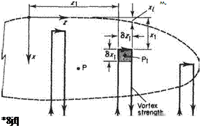
One of the infinitely many ways of constructing a suitable vortex-sheet model is suggested by Fig. 5.21. This method is certainly suitable for wings with a simple planform shape, e. g. a rectangular wing. Some wing shapes for which it is not at all suitable are shown in Fig. 5.22. Thus for the general case an alternative model is required. In general, it is preferable to assign an individual horseshoe vortex of strength k (x, z) per unit chord to each element of wing surface (Fig. 5.23). This method of constructing the vortex sheet leads to certain mathematical difficulties
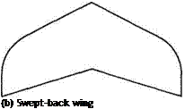
(a) Delta wing
Fig. 5.22
Fig. 5.23 Modelling the lifting effect by a distribution of horseshoe vortex elements
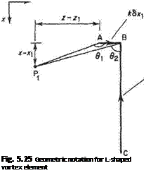
Fig. 5.24 Equivalence between distributions of (a) horseshoe and (b) L-shaped vortices when calculating the induced velocity. These problems can be overcome by recombining the elements in the way depicted in Fig. 5.24. Here it is recognized that partial cancellation occurs for two elemental horseshoe vortices occupying adjacent span – wise positions, z and z + 6z. Accordingly, the horseshoe-vortex element can be replaced by the L-shaped vortex element shown in Fig. 5.24. Note that although this arrangement appears to violate Helmholtz’s second theorem, it is merely a mathematically convenient way of expressing the model depicted in Fig. 5.23 which fully satisfies this theorem.


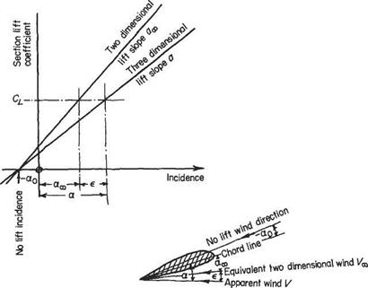
![]() This is Prandtl’s integral equation for the circulation Г at any section along the span in terms of all the aerofoil parameters. These will be discussed when Eqn (5.59) is reduced to a form more amenable to numerical solution. To do this the general series expression (5.45) for Г is taken:
This is Prandtl’s integral equation for the circulation Г at any section along the span in terms of all the aerofoil parameters. These will be discussed when Eqn (5.59) is reduced to a form more amenable to numerical solution. To do this the general series expression (5.45) for Г is taken:


