Category Aerodynamics of Wings and Bodies

The Representation of Ф in Terms of Boundary Values

Let us consider a motion of the type treated in the foregoing sections and examine the question of finding Фр at a certain point (x, y, z) arbi­trarily located in the flow field. For this purpose we turn to the reciprocal theorem (2-12), making Ф the velocity potential for the actual flow and

image271

r лДзГ— Xi)2 + (у — Ух)2 + (z — Zx)2


Here (xi, yi, Z) is any other point, one on th; boundary for instance. See Fig. 2-1. By direct substitution in Laplace’s equation, it is easy to prove that

Подпись:image28Подпись: (2-19)vV = v2

everywhere except in the immediate vicinity of r = 0, where the La – placian has an impulsive behavior corresponding to the local violation of the requirement of continuity.

Подпись: П Fig. 2-і. Arbitrary point P in liquid flow produced by general motion of an inner boundary S.

Подпись: Small spherical surface a

If we are to use the reciprocal theorem, which requires that the Laplacians of both members vanish, we must exclude the point P from the volume V. This we do by centering a small spherical surface a around the point, and we obtain

§i%ds + §*%^-§i’!ids + §t,!iAr- <2-20>

<f S-f-2 a

Inserting the value of Ф’, we rewrite this

a S+2

-#*£0) <2-21)

S+2 <r

If we let <7 become a very small sphere, then

da = r2 da, (2-22)

where dQ is an element of solid angle such that

Over the surface of a,

image30(2-24)

Подпись: -ФР image32 Подпись: —47гФр. (2-25)
image31

By the mean value theorem of integration, it is possible to replace the finite, continuous Ф by Фр in the vicinity of the point P to an acceptable degree of approximation. These considerations lead to

в»#?*і*_(!*)

<r—*0 J J P ^/mean r—»0 J J

The Representation of Ф in Terms of Boundary Values Подпись: (2-26)

Moreover, although дФ/дп varies rapidly over <r, it will always be possible to find a bounded average value (дФ/дп)т(.ап such that

Подпись: Hence
* = -§£s;ds + §*iQ*)ds-

S+2 S+S

In the limit as the outer boundary goes to infinity, with the liquid at rest there, one can show that the integrals over 2 vanish, leaving

All the manipulations in (2-27) and (2-28) on the right-hand sides should be carried out using the variables aq, уb zi. In particular, the normal derivative is expressed in terms of these dummy variables.

The reader will be rewarded by a careful examination of some of the deductions from these results that appear in Sections 57 and 58 of Lamb (1945). For instance, by imagining an artificial fluid motion which goes on in the interior of the bounding surface S, it is possible to reexpress (2-28) entirely in terms of either the boundary values of Ф or its normal derivative. Thus, the determinate nature of the problem when one or the other of these quantities is given from the boundary conditions be­comes evident.

The quantities —1/47гг and д/дп(1/4тгг), which appear in the integrands of (2-27) and (2-28), are fundamental solutions of Laplace’s equation that play the role of Green’s functions in the representation of the velocity potential. Their names and physical significances are as follows.

1.

image33

The Point Source

where r may be regarded as the radial coordinate in a set of spherical coordinates having the origin at the center of the source. The radial velocity component is whereas the other velocity components vanish. Evidently we have a spherically symmetric outflow with radial streamlines. The volume efflux from the center is easily shown to equal unity. The equipotential surfaces are concentric spheres.

A negative source is referred to as a point sink and has symmetric inflow. When the strength or efflux of the source is different from unity, a strength factor H [dimensions (length)3 (time)-1] is normally applied in (2-29) and (2-30).

2. The Doublet. The derivative of a source in any arbitrary direction s is called a doublet,

image34(2-31)

In particular, a doublet centered at the point (aq, ylt zi) and oriented in the г-direction would have the velocity potential

image35(2-32)

By examining the physical interpretation of the directional derivative, we see that a doublet may be regarded as a source-sink pair of equal strengths, with the line between them oriented in the direction of the doublet’s axis, and carried to the limit of infinitesimal separation between them. As this limit is taken, the individual strengths of the source and sink must be allowed to increase in inverse proportion to the separation.

Sources and doublets have familiar two-dimensional counterparts, whose potentials can be constructed by appropriate superposition of the three­dimensional singular solutions. There also exist more complicated and more highly singular solutions of Laplace’s equation, which are obtained by taking additional directional derivatives. One involving two differenti­ations is known as a quadrupole, one with three differentiations an octu – pole, and so forth.

Thin-wing Theory

4- 1 Introduction

In this chapter we shall derive the equations of motion governing the sub – or supersonic flow around thin wings. Although this problem may be handled by simpler regular perturbation methods, we shall here instead use the method of matched asymptotic expansions for basically two reasons. First, the present method gives a clearer picture of the usual linearized formulation as that for an outer flow for which the wing in the limit collapses onto a plane (taken to be z = 0). Secondly, the similarities and dissimilarities between the airfoil problem and that for a slender body of revolution, which will be treated in the following chapter, will be more readily apparent; in fact, as will later be seen, the slender-body theory formulation can be obtained from the two-dimensional airfoil case by means of a simple modification of the inner solution.

The procedure will be carried out in detail for two-dimensional flow only, but the extension to three dimensions is quite straightforward. The first term in the series expansion leads to the well-known linearized wing theory. In this chapter, the solutions for two-dimensional flow are given as examples. Three-dimensional wings will be considered in later chapters. The case of transonic flow requires special treatment and will be deferred to Chapter 12.

4- 2 Expansion Procedure for the Equations of Motion

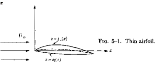
Anticipating the three-dimensional wing case, for which the standard choice is to orient the wing in the x, y-plane, we shall this time consider two-dimensional flow in the x, «-plane around a thin airfoil located mainly along the ж-axis with the free stream of velocity [/„ in the direction of the positive ж-axis as before. Thus, referring to Fig. 5-1, we let the location of the upper and lower airfoil surfaces be given by

zu = tfu(x) = тд(х) + вЦх) — ax zi = ifi(x) = —тд(х) + вЛ{ x) — ax,

where e is a small dimensionless quantity measuring the maximum cross­wise extension of the airfoil, r its thickness ratio, a the angle of attack, and 0 is a measure of the amount of camber. The functions g(x) and h(x)

81

define the distribution of thickness and camber, respectively, along the chord. It will be assumed that g and h are both smooth and that g’ and h1 are of order of unity everywhere along the chord. A blunt leading edge is thus excluded. In the limit of e —» 0 the airfoil collapses to a segment along the z-axis assumed to be located between x = 0 and x = c. We will seek the leading terms in a series expansion in e of Ф to be used as an approximation for thin airfoils with small camber and angle of attack.

For two-dimensional steady flow the differential equation (1-74) for Ф simplifies to

(a2 – Ф2Х)ФХХ + (a2 – Ф2)Фгг – 2ФхФгФхг = 0, (5-2)

where the velocity of sound is given by (1-67), which, for the present case, simplifies to

a2 = a2 – {Ф2Х + Ф2 – Vl). (5-3)

From Ф the pressure can be obtained using (1-64):

Подпись: Cv чМ21 •——– ^ (ф| + ф l-Ul) – 1 ■ (5-4)

2 al J )

The boundary conditions are that the flow is undisturbed at infinity and tangential to the airfoil surface. Hence

Thin-wing Theory

Фг/Фх = 6 0П г = «/u Фг/Фх = on z=eji.

Additional boundary conditions required to make the solution unique for a subsonic flow are that the pressure is continuous at the trailing edge (Kutta-Joukowsky condition) and also everywhere outside the airfoil. In a supersonic flow, pressure discontinuities must satisfy the Rankine – Hugoniot shock conditions. However, to the approximation considered here, these are always automatically satisfied. Strictly speaking, a super­

sonic flow with curved shocks is nonisentropic, and hence nonpotential, but the effects of entropy variation will not be felt to within the approxi­mation considered here, provided the Mach number is moderate.

We seek first an outer expansion of the form

Ф° = Г/„[Фо(ж, z) + €Ф?0, z) + • • •]. (5-6)

The factor U„ is included for convenience; in this manner the first partial derivatives of the Фп-terms will be nondimensional. Since the airfoil in the limit of € —> 0 collapses to a line parallel to the free stream, the zeroth – order term must represent parallel undisturbed flow. Thus

Ф°о = x. (5-7)

By introducing the series (5-6) into (5-2) and (5-3), and using (5-7), we obtain after equating terms of order e

(1 – М2)Ф°1хх-+ Ф?« = 0. (5-8)

The only boundary condition available for this so far is that flow perturba­tions must vanish at large distances,

Подпись: (5-9)і Фіг —» 0 for sjx2 + г2

The remaining boundary conditions belong to the inner region and are to be obtained by matching. The inner solution is sought in the form

Подпись:£/„[Фо(ж, z) + еФі(а;, z) + б2Ф’2(х, «) + •••], (5-10)

z = г/t. (5-11)

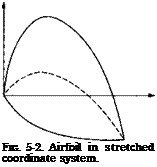
Подпись: FIG. 5-2. Airfoil in stretched coordinate system. This stretching enables us to study the flow in the immediate neighborhood of the airfoil in the limit of e —> 0 since the airflow shape then remains independent of € (see Fig. 5-2) and the width of the inner region becomes of order unity. The zeroth-order inner term is that of a parallel flow, that is, Фо = x, because the inner flow as well as the outer flow must be parallel in the limit t —> 0.

(This could of course also be obtained from the matching procedure.) From the expression for the IF-component,

Подпись: WФг = – еФІ = Ux[$Ux, z)

Подпись: (5-12)«ФггОг, г) +

we see directly that Ф} must be independent of z, say Ф = (ji(x) (which in general is different above and below the airfoil), otherwise W would not vanish in the limit of zero e. Hence (5-10) may directly be simplified to

Ф1 = U<t,[x + — є2Ф2(ж, z) + • • • ]. (5—13)

By substituting (5-13) into the differential equation (5-2) and the asso­ciated boundary condition (5-5) we find that

Фк* = 0, (5-14)

Фг = for г = Ju(x)

(5-15)

Фіі = for z = Ji(x).

Thus, the solution must be linear in z,

ФІ = Ї§+Мї), (5-16)

for z >7u, with a similar expression for 2 < fi. This result means that to lowest order the streamlines are parallel to the airfoil surface throughout the inner region.

The inner solution cannot, of course, give vanishing disturbances at infinity since this boundary condition belongs to the outer region. We

therefore need to match the inner and outer solutions. This can be done in two ways; either one can use the limit matching principle for W or the asymptotic matching principle for Ф. From (5-16) it follows that W’ is independent of z to lowest order, hence in the outer limit 2 = oo

Wi0 = Ut(x, oo) = e^“- (5-17)

Now

W° = еФ°1г. (5-18)

Equating the inner limit (z = 0+) to (5-17), we obtain the following boundary condition:

*u(x, 0+)=J> (5-19)

and in a similar manner

Фї.(*,0-) =§• (5-20)

By matching the potential itself we find that

Viu(x) = Фї(*,0+). (5-21)

To determine it is necessary to go to a higher order in the outer solution.

To illustrate the use of the asymptotic matching principle we first express the two-term outer flow in inner variables,

Ф° = TJ*[x + ez) + • • • ], (5-22)

and then take the three-term inner expansion of this, namely

Ф0 = U„[x + еФ°г(х, 0+) + е2гФ°1г(х, 0+) + • ■ • ], (5-23)

which, upon reexpression in outer variables yields

Ф0 = U*[z + еФІ(х, 0+) + егФЇЛх, 0+) + • • • ]■ (5-24)

The three-term inner expansion, expressed in outer variables, reads

Подпись: x + Є$1и(х) + €2^f + e2d2u(x) +Подпись: (5-25)Подпись:

Thin-wing Theory Thin-wing Theory Thin-wing Theory

dju

with the three-term inner expansion of the two-term outer expansion as given by (5-23) leads to

as before.

From the velocity components we may calculate the pressure coefficient by use of (5-4). Expanding in e and using (5-21) we find that the pressure on the airfoil surface is given by

Cp = ~2еФ°1х(х, 0±), (5-27)

where the plus sign is to be used for the upper surface and the minus sign for the lower one.

An examination of the expression (5-25) makes clear that such a simple inner solution cannot hold in regions where the flow changes rapidly in the x-direction as near the wing edges, or near discontinuities in airfoil surface slope. For a complete analysis of the entire flow field, these must be considered as separate inner flow regions to be matched locally to the outer flow. The singularities in the outer flow that are usually encountered at, for example, wing leading edges, do not occur in the real flow and should be interpreted rather as showing in what manner the perturbations due to the edge die off at large distances. For a discussion of edge effects on the basis of matched asymptotic expansions, see Van Dyke (1964).

In the following we will use the notation

Подпись: (5-28)6ФЇ = <p,

Thin-wing Theory Подпись: (5-29) (5-30) (5-31)

where <p is commonly known as the velocity perturbation potential (the factor Ux is sometimes included in the definition). The above procedure is easily extended to three dimensions, and for ip we then obtain the follow­ing set of linearized equations of motion and boundary conditions:

where S is the part of the x, у-plane onto which the wing collapses as e —> 0.

Fig. 5-3. Separation of thickness and lift problems.

Since the equations of motion and the boundary conditions are linear, solutions may be superimposed linearly. It is therefore convenient to write the solution as a sum of two terms, one giving the flow due to thickness and the other the flow due to camber and angle of attack (see Fig. 5-3). Thus we set

Подпись:where

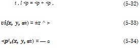
on S. It follows from (5-33) and (5-34) that <p‘ is symmetric in z whereas <pl is antisymmetric. As indicated in Fig. 5-3, represents the flow around a symmetric airfoil at zero angle of attack whereas <pl represents that around an inclined surface of zero thickness, a “lifting surface.” It will be apparent from the simple examples to be considered below that the lifting problem is far more difficult to solve than the thickness problem, at least for subsonic flow.

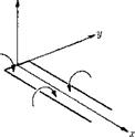
Another consequence of the lineariza­tion of the problem is that complicated solutions can be built up by superposition of elementary singular solutions. The ones most useful for constructing solu­tions to wing problems are those for a source, doublet and elementary horseshoe vortex. For incompressible flow the first two have already been discussed in Chap­ter 2. The elementary horseshoe vortex consists of two infinitely long vortex fila – pIG 5.4 – p^g eiementary ments of unit strength but opposite signs horseshoe vortex, located infinitesimally close together

image72along the positive ж-axis and joined together by an infinitesimal piece along the y-axis, also of unit strength (see Fig. 5-4).

The solution for this can be obtained by integrating the solution for a doublet in the ж-direction. Thus /•00

г___ 1 / г dxi _ 1 г Л x

* ~ J* (xj + y + z2)3/2 47r У2 + г2 y/x*

(5-35)

To extend these solutions to compressible flow the simplest procedure is to notice that by introducing the stretched coordinates

Подпись: (5-36)У = 0у, г = j8z,

Подпись: (5-37)

where /3 = /l — M2, the differential equation (5-29) transforms to the Laplace equation expressed in the coordinates x, y, z. Hence any solution to the incompressible flow problem will become a solution to the compres­sible flow if у and z are replaced by у and z. This procedure gives as a solution for the simple source

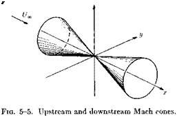
This solution could be analytically continued to supersonic flow (M > 1). However, the solution will then be real only within the two Mach cones (•y/M2 — l)r < x (see Fig. 5-5), and for physical reasons the solution within the upstream Mach cone must be discarded. Hence, since we must discard half the solution it seems reasonable that the coefficient in front of it should be increased by a factor of two in order for the total volume
output to be the same. Thus the solution for a supersonic source would read

Подпись:

Подпись: Z

J___________ 1_________

2ir Vz2 – (М2 – l)r2

A check on the constant will be provided in Chapter 6.

The use of the elementary solutions to construct more complicated ones is a method that will be frequently employed later in connection with three-dimensional wing theories. This method is particularly useful for developing approximate numerical theories. However, in the two-dimen­sional cases that will be considered next as illustrations of the linearized wing theory a more direct analytical method is utilized.

Interference and Nonplanar Lifting-Surface Theories

10- 1 Introduction

For a general discussion of interference problems and linearized theo­retical methods for analyzing them, the reader is referred to Ferrari (1957). His review contains a comprehensive list of references, and although it was editorially closed in 1955 only a few articles of fundamental importance seem to have been published since that date.

The motivation for interference or interaction studies arises from the fact that a flight vehicle is a collection of bodies, wings, and tail surfaces, whereas most aerodynamic theory deals with individual lifting surfaces, or other components in isolation. Ideally, one would like to have theoretical methods of comparable accuracy which solve for the entire combined flow field, satisfying all the various boundary conditions simultaneously. Except for a few special situations like cascades and slender wing-body configurations, this has proved impossible in practice. One has therefore been forced to more approximate procedures, all of which pretty much boil down to the following: first the disturbance flow field generated by one element along the mean line or center surface of a second element is calculated; then the angle-of-attack distribution and hence the loading of the second element are modified in such a way as to cancel this “inter­ference flow field” due to the first. Such interference effects are worked out for each pair of elements in the vehicle which can be expected to inter­act significantly. Since the theories are linear, the various increments can be added to yield the total loading.

There are some pairs of elements for which interference is unidirectional. Thus a supersonic wing can induce loading on a horizontal stabilizer behind it, whereas the law of forbidden signals usually prevents the stabilizer from influencing the wing. In such cases, the aforementioned procedure yields the exactly correct interference loading within the limits imposed by linearization. When the interaction is strong and mutual, as in the case of an intersecting wing and fuselage, the correct combined flow can be worked out only by an iteration process, a process which seems usually to be stopped after the first step.

Interference problems can be categorized by the types of elements involved. The most common combinations are listed below.

(1) Wing and tail surfaces.

(2) Pairs or collections of wings (biplanes or cascades).

(3) Nonplanar lifting surfaces (T – and V-tails, hydrofoil-strut combi­nations).

(4) Wing or tail and fuselage or nacelle.

(5) Lifting surface and propulsion system, especially wing and propeller.

(6) Tunnel boundary, ground and free-surface effects.

It is also convenient to distinguish between subsonic and supersonic steady flight, since the flow fields are so different in’the two conditions.

In the present discussion, only the first three items are treated, and even within this limitation a number of effects are omitted. Regarding item 4, wing-fuselage interference, however, a few comments are worth making. Following Ferrari, one can roughly separate such problems into those with large aspect-ratio, relatively unswept wings and those with highly-swept, low aspect-ratio wings. Both at subsonic and (not too high) supersonic speeds, the latter can be analyzed by slender-body methods along the lines described in Chapter 6. The wings of wider span need different approaches, depending on the Mach number [cf. Sections C, 6-11 and C, 35-50 of Ferrari (1957)]. For instance, subsonically it appears to be satisfactory to replace the fuselage with an infinite cylinder and work with two-dimensional crossflow methods in the Trefftz plane.[7] At super­sonic speeds, however, the bow wave from the pointed body may have a major influence in modifying the spanwise load distribution.

Further Examination of the Rigid, Impermeable Solid

Moving Through a Constant-Density Fluid Without Circulation

This section reviews some interesting results of incompressible flow theory which highlight the similarities between the dynamics of a rigid body and constant-density flow. They are particularly useful when cal­culating the resultant forces and moments exerted by the fluid on one or more bodies moving through it. Consider a particular solid body S of the type discussed above. Let there be a set of portable axes attached to the body with origin at O’; г is the position vector measured instantaneously from O’. Let u(<) and w(t) denote the instantaneous absolute linear and angular velocity vectors of the solid relative to the fluid at rest at infinity. See Fig. 2-2. If n is the outward normal to the surface of S, the boundary condition on the velocity potential is given in terms of the motion by

ЗФ

T – = [u + w X r] • n = u • n —(— и ■ (г X n) on S = 0. (2-33)

In the second line here the order of multiplication of the triple product has been interchanged in standard fashion.

Now let Ф be written as
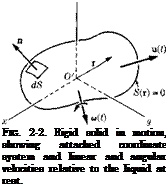
Подпись: FIG. 2-2. Rigid solid in motion, showing attached coordinate system and linear and angular velocities relative to the liquid at rest. Ф = u – ф + ы-Х. (2-34)

Assuming the components of the vectors ф and X to be solutions of Laplace’s equation dying out at in­finity, the flow problem will be solved if these coefficients of the linear and angular velocity vectors are made to satisfy the following boundary conditions on S:

P – = г X n. (2-36) dn

Evidently ф and X are dependent on the shape and orientation of S, but not on the instantaneous magnitudes of the linear and angular veloci­ties themselves. Thus we see that the total potential will be linearly de­pendent on the components of u and w. Adopting an obvious notation for the various vector components, we write

Turning to (2-11), we determine that the fluid kinetic energy can be expressed as

T = ~ f + г)] dS

s s

= + Bv2 + Cw2 + 2 A’vw + 2B’wu + 2C’uv

+ Pp2 + Qq2 + Rr2 + 2 P’qr + 2Q’rp + 2 R’pq + 2 p[Fu + Gv + Hw) + 2q[F’u + G’v + H’w]

+ 2r[F"u + G"v + H"w]}. (2-38)

Careful study of (2-37) and the boundary conditions reveals that A, B, C, . . . are 21 inertia coefficients directly proportional to density p and dependent on the body shape. They are, however, unaffected by the instantaneous motion. Therefore T is a homogeneous, quadratic function of u, v, w, p, q, and r.

By using (2-35) and (2-36) and the reciprocal theorem (2-12), the following examples can be worked out without difficulty:

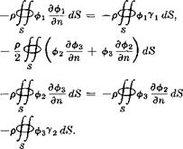
Подпись: A = A' = image37(2-39)

(2-40)

Here 71 and 72 are the direction cosines of the unit normal with respect to the x – and у-axes, respectively.

Further Examination of the Rigid, Impermeable Solid Подпись: (2-41)

Some general remarks are in order about the kinetic energy. First, we observe that the introduction of more advanced notation permits a sys­tematization of (2-38). Thus, in terms of matrices,

The first and last factors here are row and column matrices, respectively, while the central one is a 6 X 6 symmetrical square matrix of inertia coefficients, whose construction is evident from (2-38). In the dyadic or tensor formalism, we can express T

Ї1 — • M • u “T u • S • ш – j – 2^ • I * w. (2—42)

Here M and I are symmetric tensors of “inertias ” and “moments of inertia, ” while S is a nonsymmetrical tensor made up of the inertia coefficients which couple the linear and angular velocity components. For instance, the first of these reads

M = Aii + 5jj + Ckk + A'[ jk + kj] + B'[lsi + ik] + C'[ij + ji],

(2-43)

(Of course, the tensor summation notation might be used in place of dyadics, but the differences are trivial when we are working in Cartesian frames of reference.)

It is suggestive to compare (2-38) with the corresponding formula for the kinetic energy of a rigid body,

Ti = mu2 + v2 + w2] + %[p2Ixx + q2Ivy + r2Izz]

— [Iyzqr – F Izxrp + IxyPq]

+ m{x(vr — ivq) + 1j(wp — ur) + z(uq — vp)}. (2-44)

Here standard symbols are used for the total mass, moments of inertia, and products of inertia, whereas x, y, and z are the coordinates of the center of gravity relative to the portable axes with origin at O’. For many purposes, it is convenient to follow Kirchhoff’s scheme of analyzing the motion of a combined system consisting of the fluid plus the solid body. It turns out to be possible to derive Lagrangian equations of motion for this combined system, which are little more complex than those for the solid alone.

Another important point concerns the existence of principal axes. It is well known that the number of inertia coefficients for the rigid body can be reduced from ten to four by working with principal axes having their origin at the center of gravity. By analogy with this result, or by reference to the tensor character of the arrays of inertia coefficients, one can show that an appropriate rotation of axes causes the off-diagonal terms of M to vanish, while a translation of the origin O’ relative to S converts I to a diagonal, thus reducing the 21 to 15 inertia coefficients. Sections 124 to 126 of Lamb (1945) furnish the details.

For present purposes, we focus on how the foregoing results can be used to determine the forces and moments exerted by the fluid on the solid.

Further Examination of the Rigid, Impermeable Solid Further Examination of the Rigid, Impermeable Solid

It is a well-known theorem of dynamics, for a system without potential energy, that the instantaneous external force F and couple M are related to the instantaneous linear momentum £ and angular momentum Л by

Further Examination of the Rigid, Impermeable Solid Подпись: (2-47)

Furthermore, these momenta are derivable from the kinetic energy by equations which may be abbreviated

Подпись:dTi

дш

The notation for the derivatives is meaningful if the kinetic energy is written in tensor form, (2-42). To assist in understanding, we write out the component forms of (2-47),

£1 = dTi/du, £2 = dTi/dv, £3 = dTi/dw. (2-49a, b,c)

Lagrange’s equations of motion in vector notation are combining (2-45) through (2-48), as follows:

derived by

^5

II

(2-50)

— !(£)•

(2-51)

The time derivatives here are taken with respect to a nonrotating, non­translating system of inertial coordinates. Some authors prefer these results in terms of a time rate of change of the momenta as seen by an observer rotating with a system of portable axes. If this is done, and if we recognize that there can be a rate of change of angular momentum due to a translation of the linear momentum vector parallel to itself, we can replace (2-45) and (2-46) with

(2-52)

(2-53)

The subscript p here refers to the aforementioned differentiation in portable axes. Corresponding corrections to the Lagrange equations are evident.

Since the foregoing constitute a result of rigid-body mechanics, we attempt to see how these ideas can be extended to the surface S moving through an infinite mass of constant-density fluid. For this purpose, we associate with £ and X the impulsive force and impulsive torque which would have to be exerted over the surface of the solid to produce the motion instantaneously from rest. (Such a combination is referred to as a “wrench.”) In view of the relationship between impulsive pressure and velocity potential, the force and torque can be written

These so-called “Kelvin impulses” are no longer equal to the total fluid momenta; the latter are known to be indeterminate in view of the non­vanishing impulses applied across the outer boundary in the limit as it is taken to infinity. Nevertheless, we shall show that the instantaneous force and moment exerted by the body on the liquid in the actual situation are determined from the time rates of change of £ and X.

To derive the required relationship, we resort to a partially physical reasoning that follows Chapter 6 of Lamb (1945). Let us take the linear force and linear impulse for illustration purposes and afterwards deduce the result for the angular quantities by analogy.

Consider any flow with an inner boundary S and an outer boundary 2, which will later be carried to infinity, and let the velocity potential be Ф. Looking at a short interval between a time t0 and a time t, let us imagine that just prior to t0 the flow was brought up from rest by a system of impulsive forces (—рф0) and that, just after t1: it was stopped by —(—рФі). The total time integral of the pressure at any point can be broken up into two impulsive pieces plus a continuous integral over the time interval.

The first integral on the right here vanishes because the fluid is at rest prior to the starting impulse and after the final one. Also these impulses make no appreciable contribution to the integral of Q2/2.

Suppose now that we integrate these last two equations over the inner and outer boundaries of the flow field, simultaneously applying the unit normal vector n so as to get the following impulses of resultant force at these boundaries:

We assert that each of these impulses must separately be equal to zero if the outer boundary 2 is permitted to pass to infinity. This fact is obvious if we do the integration on the last member of (2-57),

The integral of the term containing the constant in (2-57) vanishes since a uniform pressure over a closed surface exerts no resultant force. Further­more, the integral of Q2/2 vanishes in the limit because Q can readily be shown to drop off at least as rapidly as the inverse square of the distance from the origin. The overall process starts from a condition of rest and ends with a condition of rest, so that the resultant impulsive force exerted over the inner boundary and the outer boundary must be zero. Equation (2-58) shows that this impulsive force vanishes separately at the outer boundary, so we are led to the result

f[nf‘1+ pdtdS = 0. (2-59)

a

In view of (2-59), the right-hand member of (2-56) can then be inte­grated over S and equated to zero, leading to

Jjnj*1 pdtdS = f^^dt = jj[—рФі — (—рФ0)]пй5 = ki ~ 5o-

s ° ° s (2-60)

Finally, we hold t0 constant and differentiate the second and fourth mem­bers of (2-60) with respect to fi. Replacing <i with t, since it may be regarded as representing any given instant, we obtain

F = f – (2-61)

This is the desired result. It is a simple matter to include moment arms in the foregoing development, thus working with angular rather than

Подпись: (2-62)

linear momentum, and derive

where Л is the quantity defined by (2-55). The instantaneous force and instantaneous moment about an axis through the origin O’ exerted by the body on the fluid are, respectively, F and M.

If we combine with the foregoing the considerations which led to (2-52) and (2-53), we can reexpress these last relationships in terms of rates of change of the Kelvin linear and angular impulses seen by an observer moving with the portable axes,

(2-63)

(2-64)

Подпись: and Further Examination of the Rigid, Impermeable Solid Further Examination of the Rigid, Impermeable Solid

As might be expected by comparison with rigid body mechanics, fj and can be obtained from the fluid kinetic energy T. The rather artificial and tedious development in Lamb (1945) can be bypassed by carefully examin­ing (2-38). The integrals there representing the various inertia coefficients are taken over the inner bounding surface only, and it should be quite apparent, for example, that the quantity obtained by partial differentiation with respect to и is precisely the ж-component of the linear impulse defined by (2-54); thus one finds

The dyadic contraction of these last six relations is, of course, similar to (2-47) and (2-48).

Further Examination of the Rigid, Impermeable Solid Further Examination of the Rigid, Impermeable Solid

Suitable combinations between (2-65)-(2-66) and (2-61)-(2-64) can be regarded as Lagrange equations of motion for the infinite fluid medium bounded by the moving solid. For instance, adopting the rates of change as seen by the moving observer, we obtain

In the above equations, Fbody and Mbody are the force and moment exerted by the fluid on the solid, which are usually the quantities of interest in a practical investigation.

2-5 Some Deductions from Lagrange’s Equations of Motion in Particular Cases

In special cases we can deduce a number of interesting results by exam­ining (2-67)-(2-68) together with the general form of the kinetic energy, (2-38).

1. Uniform Rectilinear Motion. Suppose a body moves at constant velocity u and without rotation, so that и = 0. The time derivative terms in (2-67) and (2-68) vanish, and they may be reduced to

If body = 0, (2-69)

Mbody = – u X ~ ■ (2-70)

The fact that there is no force, either drag or lift, on an arbitrary body moving steadily without circulation is known as d’Alembert’s paradox. A pure couple is found to be experienced when the linear Kelvin impulse vector and the velocity are not parallel. These quantities are obviously parallel in many cases of symmetry, and it can also be proved that there are in general three orthogonal directions of motion for which they are parallel, in which cases the entire force-couple system vanishes. Similar results can be deduced for a pure rotation with u = 0.

2. Rectilinear Acceleration. Suppose that the velocity is changing so that u = u(t), but still w = 0. Then a glance at the general formula for kinetic energy shows that

дТ^.дТ. ЗГ ЭГ

5u 1 du ^ dv dw

= і [Am + C’v + B’w] + }[Bv – f A’w + C’u]

+ к[Cw + A’v + B’u] = M u. (2-71)

This derivative is a linear function of the velocity components. Therefore,

Fbody = – M ~ ■ (2-72)

For instance, if the acceleration occurs entirely parallel to the ж-axis, the force is still found to have components in all three coordinate directions:

рьjC’g-M’g. (2-73)

It is clear from these results why the quantities A, B, . . . , are referred to as virtual masses or apparent masses. In view of the facts that the

virtual masses for translation in different directions are not equal, and that there are also crossed-virtual masses relating velocity components in different directions, the similarity with linear acceleration of a rigid body is only qualitative.

3. Hydrokinetic Symmetries. Many examples of reduction of the system of inertia coefficients for a body moving through a constant-density fluid will be found in Chapter 6 of Lamb (1945). One interesting specialization is that of a solid with three mutually perpendicular axes of symmetry, such as a general ellipsoid. If the coordinate directions are aligned with these axes and the origin is taken at the center of symmetry, we are led to

T = ЦАи2 + Bv2 + Cw2 + Pp2 + Qq2 + Rr2]. (2-74)

The correctness of (2-74) can be reasoned physically because the kinetic energy must be independent of a reversal in the direction of any linear or angular velocity component, provided that its magnitude remains the same. It follows that cross-product terms between any of these components are disallowed. Here we can see that a linear or angular acceleration along any one of the axes will be resisted by an inertia force or couple only in a sense opposite to the acceleration itself. This is a result which also can be obtained by examination of the physical system itself.

Thin Airfoils in Incompressible Flow

Considering first the symmetric problem for an airfoil at M = 0 of chord c we seek a solution of

<Pxz + Vzz = 0, (5-39)

subject to the boundary conditions that

<рг(х, 0±) = ±r ^ for 0 < x < c (5-40)

and that the disturbance velocities are continuous outside the airfoil and vanish for v/a:2 + z2 —» oo. Since we are dealing with the Laplace equa­tion in two dimensions, the most efficient approach is to employ complex variables. Let

Y = x + гг

V?(Y) = <p(x, z) + гф(х, z) (5-41)

dW, . . , ,

q = – j=: = u(x, z) — iw(x, z),


where q is the complex perturbation velocity vector made dimensionless through division by U„. In this way we assure that, provided Ф is analytic in Y, <p and Ф, as well as q, are solutions of the Laplace equation. Thus we may concentrate on finding a q(Y) that satisfies the proper boundary conditions. In the nonlifting case we seek a q(Y) that vanishes for | Y —> oo and takes the value

q(x, 0±) = u(x, 0±) — iw(x, 0±)

= u0(x) =F iw0(x), say, for 0 < x < c, (5-42)

where

w0(x) = T~ (5-43)

The imaginary part of q(Y) is thus discontinuous along the strip z = 0, 0 < x < c, with the jump given by the tangency condition (5-40). In order to find the pressure on the airfoil we need to know u0, because from (5-31)

Cp(x, 0) = —2<px(x, 0) = — 2w0. (5-44)

To this purpose we make use of Cauchy’s integral formula which states that given an analytic function /(Fx) in the complex plane Fx = X + iz, its value in the point = Y is given by the integral

/(F) – 2ш? с Y] – Y’ (5’45)

Подпись: X2] FIG. 5-6. Integration path in the complex plane.

where C is any closed curve enclosing the point Fx = Y, provided /(Fx) is analytic everywhere inside C. We shall apply (5-45) with / = q and an integration path C selected as shown in Fig. 5-6.

Thin Airfoils in Incompressible Flow Подпись: (5-46)

The path was chosen so as not to enclose completely the slit along the real axis representing the airfoil because q is discontinuous, and hence nonanalytic, across the slit. Thus

In the limit of Ri —> oo the integral over Ci must vanish, since from the boundary conditions q(Yj) —> 0 for Yi —> oo. The integrals over the two paths C2 cancel; hence

Подпись:m _L f q(Y i) dY і J_ f° А д(хг) dxx

qK > 2wiJc3 Yi – Y 2mJo xx — Y ’

where Aq is the difference in the value of q between the upper and lower sides of the slit. From (5-42) it follows that

Ag(xi) = q(xu 0+) — q(xu 0—) = —2гад0(ж1). (5-48)

Подпись: q(Y) = Подпись: 1 f w0(xi) dxі ж Jo Подпись: (5-49)

Hence, upon inserting this into (5-47), we find that

Thin Airfoils in Incompressible Flow Подпись: (5-50) (5-51)

which, together with (5-43), gives the desired solution in terms of the air­foil geometry. Separation of real and imaginary parts gives

Подпись: u(x, z)

Thin Airfoils in Incompressible Flow

In the limit of г —» 0+ the second integral will receive contributions only from the region around xx = x and is easily shown to yield w0 as it should. To obtain a meaningful limit for the first integral, we divide the region of integration into three parts as follows:

Подпись: 1Подпись: 7ГПодпись: XI)WQ(XI) dxi - Xi)2 + z2image75(5-52)

where 6 is a small quantity but is assumed to be much greater than z. We may, therefore, directly set z = 0 in the first and third integrals. In
the second one, we may, for small S, replace w0(xi) by w0(x) as a first approximation, whereupon the integrand becomes antisymmetric in ж — x and the integral hence vanishes. The integral (5-50) is therefore in the limit of z = 0 to be interpreted as a Cauchy principal value integral (as indicated by the symbol C):

Uo{x) = lf^(xiUxl! (5-53)

IT J0 x — Xi

Подпись: dx і Thin Airfoils in Incompressible Flow Подпись: (5-54)

which is therefore defined as

Turning now to the lifting case, we recall that и is antisymmetric in z, and w symmetric. Consequently, on the airfoil,

w{x, 0) = w0(x) = в ^ — a (5-55)

is the same top and bottom, and in (5-45) then

Дq = u(x, 0+) — u(x, 0—) = 2u0(x) = У(х), (5-56)

Thin Airfoils in Incompressible Flow Thin Airfoils in Incompressible Flow

where У(х) is the nondimensional local strength of the vortices distributed along the chord. Hence, (5-47) will yield the following integral formula

This is the integral equation of thin airfoil theory first considered by Glauert (1924). Instead of attacking (5-58) we will use analytical tech­niques similar to those used above to obtain directly a solution of the complex velocity q(Y). This solution will then, of course, also provide a solution of the singular integral equation (5-58). For a more general treatment of this kind we refer to the book by Muskhelishvili (1953).

Again, we shall start from Cauchy’s integral formula (5-45) but this time we instead choose

f(Y) = g(Y)h(Y), (5-59)

where h(Y) is an analytic function assumed regular outside the slit and sufficiently well behaved at infinity so that /(F) —> 0 for Y —> сю.

(5-66)

For the integral to converge, m and n cannot be smaller than —1. Further­more, since the integral for large |F| vanishes like F-1 we must choose

Подпись:

Подпись: (5-60)
Подпись: (5-62)

m + n > —1

in order for q to vanish at infinity. It follows from (5-66) that in the neighborhood of the leading edge

q ~ Y~m~112, (5-68)

whereas near the trailing edge

q ~ (c – Y)-n~112. (5-69)

From the latter it follows that the Kutta-Joukowsky condition of finite velocity at the trailing edge is fulfilled only if n < —1. Hence from what was said earlier the only possible choice is

n = -1. (5-70)

From m we then find from (5-67) that it cannot be less than zero. It seems reasonable from a physical point of view that the lowest possible order of singularity of the leading edge should be chosen, namely

m = 0. (5-71)

Thin Airfoils in Incompressible Flow

However, from a strictly mathematical point of view there is nothing in the present formulation that requires this choice; thus any order singu­larity could be admissible. In settling this point the method of matched asymptotic expansions again comes to the rescue. The present formulation holds strictly for the outer flow only, which was matched to the inner flow near the airfoil. However, as was pointed out in Section 5-2, the simple inner solution (5-25) obviously cannot hold near the leading edge since there the ж-derivatives in the equation of motion will become of the same order as z-derivativ’es. To obtain the complete solution we therefore need to consider an additional inner region around the leading edge which is magnified in such a manner as to keep the leading edge radius finite in the limit of vanishing thickness. Such a procedure shows (Van Dyke, 1964) that the velocity perturbations due to the lifting flow vanish as Y~~1/2 far away from the leading edge. Hence (5-71) is verified and consequently

which is a solution of the integral equation (5-58).

As a simple illustration of the theory the case of an uncambered airfoil will be considered. Then for the lifting flow

Подпись:Подпись: (5-75)w0 = —a

and for (5-73) we therefore need to evaluate the integral

j = J_ / dx і I X Д

7Г Jo X — Xi С — X1

Thin Airfoils in Incompressible Flow Подпись: I dx і 0 Y — X! Подпись: (5-76)
image76

This rather complicated integral may be handled most conveniently by use of the analytical techniques employed above. Using analytical con­tinuation, (5-75) is first generalized by considering instead the complex integral

Подпись: }{Y) = Подпись: (5-77)
image77

whose real part reduces to (5-75) for г = 0+. Now we employ Cauchy’s integral formula (5-45) with

and the same path of integration as considered previously (see Fig. 5-6). Thus

Подпись:Подпись: (5-78)1+C2+C3 Y

Подпись: J_ [ dYг ( Ft V/2 2TriJCl Fi - Yc - Yj Подпись: 1 2тгг Подпись: ^і[г + 0(УГ1)] c, У і Подпись: г.

Along the large circle C1 we find by expanding the integrand in Ff1

image79,image80,image81 Подпись: = ІЗ. (5-79)

The integral over С2 cancels as before, whereas the contribution along C3 becomes

Подпись: (2-157)Taking the real part of this for z = 0+ we obtain

/ = -1 (5-81)

and, consequently, by introducing (5-74) into (5-73),

u(x, 0+) = a = щ(х). (5-82)

Hence the lifting pressure distribution

ДCp = Cp(x, 0—) – Cp(x, 0+) = 4u0(x) = 4a (5-83)

has a square-root singularity at the leading edge and goes to zero at the trailing edge as the square root of the distance to the edge. The same behavior near the edges may be expected also for three-dimensional wings.

The total lift is easily obtained by integrating the lifting pressure over the chord. An alternative procedure is to use Kutta’s formula

L = р{7«,Г.

The total circulation Г around the airfoil can be obtained by use of (5-72). Thus

– -"-far-

Thin Airfoils in Incompressible Flow

The path of integration around the airfoil is arbitrary. Taking it to be a large circle approaching infinity we find that

For the flat plate this leads to the well-known result

In view of the linearity of camber and angle-of-attack effects, the lift – curve slope should be equal to 2ir for any thin profile. Most experiments show a somewhat smaller value (by up to about 10%). This discrepancy is usually attributed to the effect of finite boundary layer thickness near the trailing edge, which causes the rear stagnation point to move a small distance upstream on the upper airfoil surface from the trailing edge with an accompanying loss of circulation and lift. This effect is very sensitive to trailing-edge angle. For airfoils with a cusped trailing edge (= zero

trailing-edge angle), carefully controlled experiments give very nearly the full theoretical value of lift-curve slope.

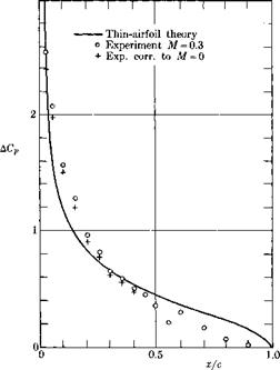
According to thin-airfoil theory, the lifting pressure distribution is given by (5-83) for all uncambered airfoils. Figure 5-7 shows a comparison between this theoretical result and experiments for an NACA 0015 airfoil performed by Graham, Nitzberg, and Olson (1945). The lowest Mach number considered by them was M = 0.3, and the results have therefore been corrected to M = 0 using the Prandtl-Glauert rule (see Chapter 7). The agreement is good considering the fairly large thickness (15%), except near the trailing edge. The discrepancy there is mainly due to viscosity as discussed above. It is interesting to note that the theory is accurate very close to the leading edge despite its singular behavior at x = 0 discussed earlier. In reality, ДCp must, of course, be zero right at the lead­ing edge.

With the aid of the Prandtl-Glauert rule the theory is easily extended to the whole subsonic region (see Section 7-1). The first-order theory has

image82

Fig. 5-7. Comparison of theoretical and experimental lifting pressure distribu­tions on a NACA 0015 airfoil at 6° angle of attack. [Based on experiments by Graham, Nitzberg, and Olson (1945).]

been extended by Van Dyke (1956) to second order. He found that it is then necessary to handle the edge singularities appearing in the first-order solution carefully, using separate inner solutions around the edges; other­wise an incorrect second-order solution would be obtained in the whole flow field.

Interfering or Nonplanar Lifting Surfaces in Subsonic Flow

A unified theory of interference for three-dimensional lifting surfaces in a subsonic main stream can be built up around the concept of pressure or acceleration-potential doublets. We begin by appealing to the Prandtl – Glauert-Gothert law, described in Section 7-1, which permits us to restrict ourselves to incompressible fluids. Granted the availability of high-speed computing equipment, it then proves possible to represent the loading distribution on an arbitrary collection of surfaces (biplane, multiplane, T-tail, V-tail, wing-stabilizer combination, etc.) by distributing appropri­ately oriented doublets over all of them and numerically satisfying the flow-tangency boundary condition at a large enough set of control points. The procedure is essentially an extension of the one for planar wings that is sketched in Section 7-6.

Two observations are in order about the method described below. First it overlooks two sometimes significant phenomena that occur when applied to a pair of lifting surfaces aligned stream wise (e. g., wing and tail). These are the rolling up of the wake vortex sheet and finite thickness or reduced dynamic pressure in the wake due to stalling. They are reviewed at some length in Sections C,2 and C,4 of Ferrari (1957).

The second remark concerns thickness. In what follows, we represent the lifting surfaces solely with doublets, which amounts to assuming negligible thickness ratio. When two surfaces do not lie in the same plane, however, the flow due to the thickness of one of them can induce inter­ference loads on the other, as indicated in Fig. 11-1. The presence of this thickness and the disturbance velocities produced at remote points thereby may be represented by source sheets in extension of the ideas set forth in Section 7-2. Since the procedure turns out to be fairly straightforward, it is not described in detail here.

The necessary ideas for analyzing most subsonic interference loadings of the type listed under items 1, 2, and 3 can be developed by reference to the thin, slightly inclined, nonplanar lifting surface illustrated in Fig.

10- 2. We use a curvilinear system of coordinates x, s to describe the surface of S, and the normal direction n is positive in the sense indicated. The small camber and angle of attack, described by the vertical deflection Az(x, y) or corresponding small normal displacement Дn(x, s), are super­imposed on the basic surface z0(y). The latter is cylindrical, with generators in the free-stream ж-direction. To describe the local surface slope in y, г-planes, we use

(11-1)

Examples of Two – and Three-Dimensional Flows Without Circulation

We now look at some simple illustrations of constant-density flows without circulation, observe how the mathematical solutions are obtained, how virtual masses are determined, and how other information of physical interest is developed.

1. The Circular Cylinder. It is well known that a circular cylinder of radius c in a uniform stream Ux parallel to the negative ж-direction is represented by the velocity potential

image38(2-75)

Here r and в are conventional plane polar coordinates, and the cylinder is, of course, centered at their origin.

If we remove from this steady flow the free-stream potential

Examples of Two - and Three-Dimensional Flows Without Circulation Подпись: (2-76)
Подпись: we are left with
Examples of Two - and Three-Dimensional Flows Without Circulation

This result can be regarded as describing the motion for all time in a set of portable axes that move with the cylinder’s center. Moreover, the velocity U„ may be a function of time.

Examples of Two - and Three-Dimensional Flows Without Circulation Подпись: (2-78) (2-79)
image39

Per unit distance normal to the flow, the kinetic energy of the fluid is

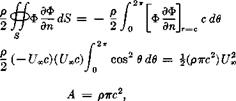
whereas the inertia coefficient В would have the same value and all other coefficients in the r, 0-plane must vanish. We reach the interesting, if accidental, conclusion that the virtual mass of the circular cylinder is precisely the mass of fluid that would be carried within its interior if it were hollowed out. This mass is the factor of proportionality which would relate an ж-acceleration to the inertial force of resistance by the fluid to this acceleration.

These same results might be obtained more efficiently using the complex variable representation of two-dimensional constant-density flow, as dis­cussed in Sections 2-9 ff.

2. Sphere of Radius R Moving in the Positive x-Direction (Fig. 2-3).

With the fluid at rest at infinity, the sphere passing the origin of coor­dinates at time t = 0 and proceeding with constant velocity Ux has the instantaneous equation, expressed in coordinates fixed to the fluid at infinity,

B(x, y, z, t) = (ж — UJ)2 + y2 + z2 — R2 = 0. (2-80)

The boundary condition may be expressed by the requirement that В is a constant for any fluid particle in contact with the surface. That is,

T)D

^ = 0 on В = 0. (2-81)

Подпись: s + Уф ’ VB 01
Подпись: -2Ux(x - UJ)

Working this out with the use of (2-80),

In this example we proceed by trial, attempting to satisfy this condition at t = 0 by means of a doublet centered at the origin with its axis in the positive ж-direction,

Подпись: dПодпись: dximage40"Подпись: (2-83)Подпись: (2-84)

Подпись: V
image41

Hx 4 жг3

Подпись: W

We calculate the velocity components

If (2-85а), (b), and (с) are inserted into (2-82), and r and t are set equal to R and 0, respectively, we are led after some algebra to a formula for the strength H of the doublet:

H = 2irR3Ux. (2-86)

The uniqueness theorem, asserted earlier in the chapter, assures that we have the correct answer.

Подпись: (2-87)2ttR3Uxx _ _ U„x R3 4irr3 2 r3

As in the case of the circular cylinder, all kinds of information can be readily obtained once the velocity potential is available. By adding the potential of a uniform stream Ux in the negative ж-direction one con­structs the steady flow and can then obtain streamlines and velocity and pressure patterns around the sphere. The only inertia coefficients are direct virtual masses. It is also of interest that the unsteady potential dies out at least as fast as the inverse square of distance from the origin when

one proceeds toward infinity, and the velocity components die out at least as the inverse cube. General considerations lead to the result that the disturbance created in a constant-density fluid by any nonlifting body will resemble that of a single doublet at remote points.

The foregoing example of the sphere is just a special case of a more general technique for constructing axially symmetric flows around bodies of revolution by means of an equilibrating system of sources and sinks along the axis of symmetry. (The doublet is known to be the limit of a single source-sink pair.) This procedure was originally investigated by Rankine, and such figures are referred to as Rankine ovoids. Among many other investigators, von Karmdn (1927) has adapted the method to airship hulls.

image42"For blunt shapes like the sphere, the results of potential theory do not agree well with what is measured because of the presence of a large sep­arated wake to the rear, a problem which we discuss further in Chapter 3. It was this sort of discrepancy that dropped theoretical aerodynamics into considerable disrepute during the nineteenth century. The blunt-body flows are described here principally because they provide simple illustra­tions. When it comes to elongated streamlined shapes, a great deal of useful and accurate information can be found without resort to the non­linear theory of viscous flow, however, and such applications constitute the ultimate objective of this book.

Fig. 2-4. Prolate ellipsoid of revolu­tion moving through constant-density fluid at an angle of attack a in the x, y- plane.

3. Ellipsoids. A complete account of the solution of more complicated boundary-value problems on spheres, prolate or oblate ellipsoids of revolu­tion, and general ellipsoids will be found in the cited references. Space considerations prevent the reproduction of such results here, with the exception that a few formulas will be given for elongated ellipsoids of revolution translating in a direction inclined to the major axis. These have considerable importance relative to effects of angle of attack on fuselages, submarine hulls, and certain missile and booster configurations.

For the case shown in Fig. 2-4, the velocity

Подпись:

Подпись: = pjvolume] image44 Подпись: Ux sin a Подпись: (2-89)
image43

u = if/», cos a + jUx sin a gives rise to a Kelvin impulse f = ІAUoo cos a + jBUa sin a

Подпись: — Theoretical (2-90) о Determined by integration FIG. 2-5. Comparison between predicted and measured moments about a cen- troidal axis on a prolate spheroid of fineness ratio 4:1. [Adapted from data reported by R. Jones (1925) for a Reynolds number of about 500,000 based on body length.]

The ellipsoid’s volume is, of course, §7гаЬ2, whereas the dimensionless coefficients

[«o/(2 — ao)L [do/(2 /So)]

are functions of eccentricity tabulated in Section 115 of Lamb (1945).

With constant speed and incidence the force is zero, but the vectors u and £ are not quite parallel and an overturning couple is generated,

Mbody = – uXf

– – k v – – 5^} ™ 2«; (2-90)

the inertia factor here in braces is always positive, vanishing for the sphere. At fineness ratios above ten it approaches within a few percent of unity. Thus the familiar unstable contribution of the fuselage to static stability is predicted theoretically. The calculations are in fairly satisfactory accord with measurements when a/b exceeds four or five. Figure 2-5 presents a comparison with pitching-moment data.