Category AERODYNAMICS

RATE OF CHANGE OF CIRCULATION: KELVIN’S THEOREM

Consider the circulation around a fluid curve (which always passes through the same fluid particles) in an incompressible inviscid flow with conservative body

Подпись: DY Dt image42 Подпись: lcDI Подпись: d + Jc Dt Подпись: (2.13)

forces acting. The time rate of change of the circulation of this fluid curve C is given as

Подпись: Dq Dt Подпись: a Подпись: and Подпись: ~ d = dq Dt 4

Since C is a fluid curve, we have

and therefore

Подпись: DY Dt image43(2.14)

since the closed integral of an exact differential that is a function of the coordinates and time only is <J>C q • dq = <J>C d(q2/2) = 0. The acceleration a is obtained from the Euler equation (Eq. (1.62)) and is

—v(£)+r

Substitution into Eq. (2.14) yields the result that the circulation of a fluid curve remains constant:

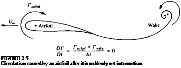
Подпись: FIGURE 2.5 Circulation caused by an airfoil after it is suddenly set into motion.

since the integral of a perfect differential around a closed path is zero and the work done by a conservative force around a closed path is also zero. The result in Eq. (2.15) is a form of angular momentum conservation and is known as Kelvin’s theorem (after the British scientist who published his theorem in 1869), which states that: the time rate of change of circulation around a closed curve consisting of the same fluid elements is zero. For example, consider an airfoil as in Fig. 2.5, which prior to t = 0 was at rest and then at f>0 was suddenly set into a constant forward motion. As the airfoil moves through the

fluid a circulation rairfoii develops around it. In order to comply with Kelvin’s theorem a starting vortex Twake must exist such that the total circulation around a line that surrounds both the airfoil and the wake remains unchanged:

^ P ^airfoil "1" Pvake 1Л

d7“ Ї,————– “° (116)

This is possible only if the starting vortex circulation will be equal to the airfoil’s circulation, but its rotation will be in the opposite direction.

RATE OF CHANGE OF VORTICITY

To obtain an equation that governs the rate of change of vorticity of a fluid element, we start with the incompressible Navier-Stokes equations in cartesian coordinates (Eq. (1.30)),

Подпись:Подпись: (2.5)cfq n

-^ + q* Vq = f— V —+ v V2q

at p

The convective acceleration term is rewritten using the vector identity

q2

q*Vq = V^- — qX?

Now take the curl of Eq. (1.30), with the second term on the left-hand side replaced by the right-hand side of Eq. (2.5). Note that for a scalar A, V x VA = 0 and therefore the pressure term vanishes:

^-VX(qX?) = Vxf+vV25 (2.6)

at

To simplify the result, we use the following vector identity,

Vx(qXt) = qV-&-q-V£ + S-Vq-tV-q (2 J)

along with the incompressible continuity equation and the fact that the vorticity is divergence-free (note that for any vector A, V • V X A = 0). If we also assume that the body force acting is conservative virrotational, such as gravity) then

VXf=0

and the rate of change of vorticity equation becomes

Подпись: (2-8)

image39,image40

= ^r + q’V^ = ^-Vq-l-v V2£ Dt dt 4 4 *

The inviscid incompressible version of the vorticity transport equation is then

fpS’Vq (2.9)

For a flow that is two-dimensional, the vorticity is perpendicular to the flow direction and Eq. (2.8) becomes

(2.10)

and for the two-dimensional flow of an inviscid, incompressible fluid

image41(2.11)

and the vorticity of each fluid element is seen to remain constant.

The vorticity equation (Eq. (2.8)) strongly resembles the Navier-Stokes equation and for very high values of the Reynolds number it is seen that the vorticity that is created at the solid boundary is convected along with the flow at a much faster rate than it can be diffused out across the flow and so it remains in the confines of the boundary layer and trailing wake. The fluid in the outer portion of the flowfield (the part that we will study) is seen to be effectively rotation-free (irrotational) as well as inviscid.

The above observation can be illustrated for the two-dimensional case using the nondimensional quantities defined in Eq. (1.46). Then, Eq. (2.10) can be rewritten in nondimensional form:

Подпись:Dt* Re z

where the Reynolds number, Re, is defined in Eq. (1.56). Here a two – dimensional flow in the x-y plane is assumed and therefore the vorticity points in the z direction. The left-hand side in this equation is the rate at which vorticity is accumulated, which is equal to the rate at which it is being generated (near the solid boundaries of solid surfaces). It is clear from Eq. (2.10a) that for high Reynolds number flows, vorticity generation is small and can be neglected outside the boundary layer. Thus for an irrotational fluid Eq.

(2.2) reduces to

dw _dv Эи _ dw dv _ du

dy dz dz Эх Эх ду

FUNDAMENTALS OF INVISCID, INCOMPRESSIBLE FLOW

In Chapter 1 it was established that for flows at high Reynolds number the effects of viscosity are effectively confined to thin boundary layers and thin wakes. For this reason our study of low-speed aerodynamics will be limited to flows outside these limited regions where the flow is assumed to be inviscid and incompressible. To develop the mathematical equations that govern these flows and the tools that we will need to solve the equations it is necessary to study rotation in the fluid and to demonstrate its relationship to the effects of viscosity.

It is the goal of this chapter to define the mathematical problem (differential equation and boundary conditions) of low-speed aerodynamics whose solution will occupy us for the remainder of the book.

2.1 ANGULAR VELOCITY, VORTICITY,

AND CIRCULATION

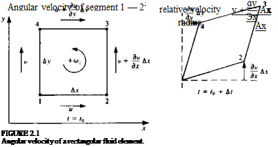
The arbitrary motion of a fluid element consists of translation, rotation, and deformation. To illustrate the rotation of a moving fluid element, consider at t = t0 the control volume shown in Fig. 2.1. Here, for simplicity, an infinitesimal rectangular element is selected that is being translated in the z = 0 plane by a velocity (n, v) of its corner no. 1. The lengths of the sides, parallel

FUNDAMENTALS OF INVISCID, INCOMPRESSIBLE FLOW Подпись: dv Эх

to the x and у directions, are Ajc and Ay, respectively. Because of the velocity variations within the fluid the element may deform and rotate and, for example, the x component of the velocity at the upper corner (no. 4) of the element will be и + (ди/ду)Ау, where higher-order terms in the small quantities Ax and Ay are neglected. At a later time (e. g., t = t0 + At), this will cause the deformation shown at the right-hand side of Fig. 2.1. The angular velocity component (oz (note positive direction in the figure follows the right-hand rule) of the fluid element can be obtained by averaging the instantaneous angular velocities of the segments 1-2 and 1-4 of the element. The instantaneous angular velocity of segment 1-2 is the difference in the linear velocities of the two edges of this segment, divided by the distance (Ax):

Подпись: Ay dy

and the angular velocity of the 1-4 segment is

The z component of the angular velocity of the fluid element is then the average of these two components

l/dv du

<°z~2di~dy)

The two additional components of the angular velocity can be obtained similarly, and in vector form the angular velocity becomes

Подпись: (2.1)ы = tV X q

It is convenient to define the vorticity £ as twice the angular velocity.

£ = 2w = VXq (2.2)

In cartesian coordinates the vorticity components are

(dv du

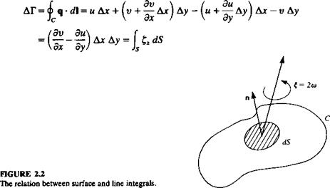
Now consider an open surface S, shown in Fig. 2.2, which has the closed curve C as its boundary. With the use of Stokes’ theorem (see Kellogg,13 p. 73) the vorticity on the surface S can be related to the line integral around C:

I V X q • n dS = j £ • n dS = Ф q • dl

Js ‘s Jc

where n is normal to S. The integral on the right-hand side is called the circulation and is denoted by Г,

Г = <j> q • d (2.3)

This relation can be illustrated again with the simple fluid element of Fig. 2.1. The circulation ДГ is obtained by the evaluation of the closed line integral of the tangential velocity component around the fluid element. Note that the positive direction corresponds to the positive direction of o>.

image36

For the general three-dimensional case these conclusions can be summarized as Г = <|> q*dl = J Vxq-n</S = jVndS (2.4)

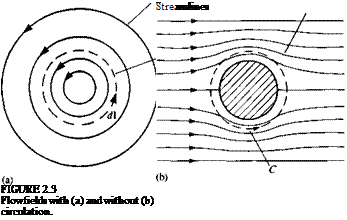
The circulation is therefore somehow tied to the rotation in the fluid (e. g., to the angular velocity of a solid body type rotation). In Fig. 2.3 two examples are shown to illustrate the concept of circulation. The curve C (dashed lines) is taken to be a circle in each case. In Fig. 2.3a the flowfield consists of concentric circular streamlines in the counterclockwise direction. It is clear that along the circular integration path C (Fig. 2.3a) q and d in Eq.

(2.3)

FUNDAMENTALS OF INVISCID, INCOMPRESSIBLE FLOW

are positive for all d and therefore C has a positive circulation. In Fig.

2.36 the flowfield is the symmetric flow of a uniform stream past a circular cylinder. It is clear from the symmetry that the circulation is zero for this case.

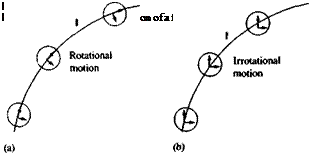
To illustrate the motion of a fluid with rotation consider the control volume shown in Fig. 2.4a, moving along the path l. Let us assume that the viscous forces are very large and the fluid will rotate as a rigid body, while following the path /. In this case V X q Ф 0 and the flow is called rotational. For the fluid motion described in Fig. 2.46, the shear forces in the fluid are negligible, and the fluid will not be rotated by the shear force of the neighboring fluid elements. In this case V X q = 0 and the flow is considered to be irrotational.

SIMILARITY OF FLOWS

Another interesting aspect of the process of nondimensionalizing the equations in the previous section is that two different flows are considered to be similar if the nondimensional numbers of Eq. (1.60) are the same. For most practical cases, where gravity and unsteady effects are negligible, only the Reynolds and the Mach numbers need to be matched. A possible implementation of this principle is in water or wind-tunnel testing, where the scale of the model differs from that of the actual flow conditions.

For example, many airplanes are tested in small scale first (e. g., l/5th scale). In order to keep the Reynolds number the same then either the airspeed or the air density must be increased (e. g., by a factor of 5). This is a typical conflict that test engineers face, since increasing the airspeed 5 times will bring the Mach number to an unreasonably high range. The second alternative of reducing the kinematic viscosity v by compressing the air is possible in only a very few wind tunnels, and in most cases matching both of these nondimensional numbers is difficult.

Another possibility of applying the similarity principle is to exchange fluids between the actual and the test conditions (e. g., water with air where the ratio of kinematic viscosity is about 1:15). Thus a 1/15-scale model of a submarine can be tested in a wind tunnel at true speed conditions. Usually it is better to increase the speed in the wind tunnel and then even a smaller scale model can be tested (of course the Mach number is not always matched but for such low Mach number applications this is less critical).

FLOW WITH HIGH REYNOLDS NUMBER

The most important outcome of the nondimensionalizing process of the governing equations is that now the relative magnitude of the terms appearing in the equations can be determined and compared. If desired, small terms can be neglected, resulting in simplified equations that are easier to solve but still contain the dominant physical effects.

Подпись: Q Подпись: + FLOW WITH HIGH REYNOLDS NUMBER Подпись: *2 FLOW WITH HIGH REYNOLDS NUMBER Подпись: (1.60)

In the case of the continuity equation all terms have the same magnitude and none is to be neglected. For the momentum equation the relative magnitude of the terms can be obtained by substituting Eqs. (1.51-1.56) into Eq. (1.50), and for the x direction we get

Подпись: Re Creeping Viscous Turbulent flow laminar flow flow

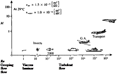
Before proceeding further, let us examine the range of Reynolds number and Mach number for some typical engineering problems. Since the viscosity of typical fluids such as air and water is very small, a large variety of practical engineering problems (aircraft low-speed aerodynamics, hydrodynamics of naval vessels, etc.) fall within the Re »1 range, as shown in Fig. 1.13. So for situations when the Reynolds number is high, the viscous terms become small compared to the other terms of order 1 in Eq. (1.60). But before neglecting

FIGURE 1.13

Range of Reynolds number and Mach number for some typical fluid flows.

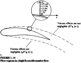
Подпись:  FIGURE 1.14 Flow regions in a high Reynolds number flow.

these terms, a closer look at the high Reynolds number flow condition is needed. As an example, consider the flow over an airfoil, as shown in Fig. 1.14. In general, based on the assumption of high Reynolds number the viscous terms of Eq. (1.60) (or 1.30) can be neglected in the outer flow regions (outside the immediate vicinity of a solid surface where V2q== order 1). Therefore, in this outer flow region, the solution can be approximated by solving the incompressible continuity and the Euler equations:

V • q = 0 (1.61)

da Vd

^ + q-Vq = f(1.62)

Equation (1.62) is a first-order partial differential equation that requires a boundary condition on one velocity component on a solid surface compared to a boundary condition on the velocity vector needed for Eq. (1.30) in the previous section. Since the flow is assumed to be inviscid, there is no physical reason for the tangential velocity component to be zero on a stationary solid surface and therefore what remains from the no-slip boundary condition (Eq. (1.28a, b) is that the normal component of velocity must be zero

qn = 0 (on solid surface) (1.63)

However, a closer investigation of such flow fields reveals that near the solid boundaries in the fluid, shear flow derivatives such as V2q become large and the viscous terms cannot be neglected even for high values of the Reynolds number (Fig. 1.14). As an example, near the surface of a streamlined two-dimensional body submerged in a steady flow in the x direction (with no body forces) the Navier-Stokes equations can be reduced to the classical
boundary-layer equations (see Schlichting,16 p. 131) where now x represents distance along the body surface and z is measured normal to the surface. The momentum equation in the x direction is

image31(1.64)

and in the normal, z direction:

image32(1.65)

So, in conclusion, for high Reynolds number flows there are two dominant regions in the flowfleld:

1. The outer flow (away from the solid boundaries) where the viscous effects are negligible. A solution for the in viscid flow in this region provides information about the pressure distribution and the related forces.

2. The thin boundary layer (near the solid boundaries) where the viscous effects cannot be neglected. Solution of the boundary-layer equations will provide information about the shear stress distribution and the related (friction) forces.

For the solution of the boundary-layer equations, the no-slip boundary condition is applied on the solid boundary. The tangential velocity profile inside the boundary layer is shown in Fig. 1.14 and it is seen that as the outer region is approached, the tangential velocity component becomes independent of z. The interface between the boundary-layer region and the outer flow region is not precisely defined and occurs at a distance <5, the boundary-layer thickness, from the wall. For large values of the Reynolds number the ratio of the boundary-layer thickness to a characteristic length of the body (an airfoil’s chord, for example) is proportional to Re m (see Schlichting,16 p. 129). Therefore, the normal extent of the boundary-layer region is negligible when viewed on the length scale of the outer region.

A detailed solution for the complete flowfleld of such a high Reynolds number flow proceeds as follows:

1. A solution is found for the inviscid flow past the body. For this solution the boundary condition of zero velocity normal to the solid surface is applied at the surface of the body (which is indistinguishable from the edge of the boundary layer on the scale of the chord). The tangential velocity component on the body surface Ue is then obtained as part of the inviscid solution and the pressure distribution along the solid surface is then determined.

2. Note that in the boundary-layer equations (Eqs. (1.64) and (1.65)) the pressure does not vary across the boundary layer and is said to be
impressed on the boundary layer. Therefore, the surface pressure distribu­tion is taken from the inviscid solution in (1) and inserted into Eq. (1.64). Also, Ue is taken from the inviscid solution as the tangential component of the velocity at the edge of the boundary layer and is used as a boundary condition in the solution of the boundary-layer equations.

The solution for a high Reynolds number flow field with the assumption of an inviscid fluid is therefore the first step towards the solution of the complete physical problem. (Additional iterations between the inviscid outer flow and the boundary-layer region in search for an improved solution are possible and are discussed in Chapters 9 and 14.)

DIMENSIONAL ANALYSIS OF THE FLUID DYNAMIC EQUATIONS

The governing equations that were developed in the previous section (e. g., Eq. (1.27)) are very complex and their solution, even by numerical methods, is difficult for many practical applications. If some of the terms causing this complexity can be neglected in certain regions of the flow field, while the dominant physical features are still retained, then a set of simplified equations can be obtained (and probably solved with less effort). In this section, some of the conditions for simplifying the governing equations will be discussed.

In order to determine the relative magnitudes of the various elements in the governing differential equations, the following dimensional analysis is performed. For simplicity, consider the fluid dynamic equations with constant properties (|U = const., and p = const.):

V-q = 0 (1.23)

p(|^ + 4* Vq) = pf-Vp + Iu V2q (1.30)

The first step is to define some characteristic or reference quantities, relevanl
to the physical problem to be studied:

L Reference length (e. g., wing’s chord)

V Reference speed (e. g., the free stream speed)

T Characteristic time (e. g., one cycle of a periodic process, or L/V)

p0 Reference pressure (e. g., free stream pressure, p„)

f0 Body force (e. g., magnitude of earth’s gravitation, g)

image24

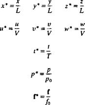
With the aid of these characteristic quantities we can define the following nondimensional variables:

If these characteristic magnitudes are properly selected, then all the non – dimensional values in Eq. (1.46) will be of the order of 1. Next, the governing equations need to be rewritten using the quantities of Eq. (1.46). As an example, the first term of the continuity equation becomes

Эи __ Эи ди* Эх* _V / du*

Эх ди* Эх* Эх Ldx*J

and the transformed incompressible continuity equation is

After a similar treatment, tl. e nomentum equation n the x direction becomes /Vdu*

.V t du*

I r w t, r „ „V Эи* ,V

p{T~dF+vr ^+Vlv‘ ^ + VIW dz

dy*

Podp* ^ Pfofx L Эх*

V (Э2и* д2и* д2и* – h—~r +

Подпись:

DIMENSIONAL ANALYSIS OF THE FLUID DYNAMIC EQUATIONS DIMENSIONAL ANALYSIS OF THE FLUID DYNAMIC EQUATIONS DIMENSIONAL ANALYSIS OF THE FLUID DYNAMIC EQUATIONS

V/Эи* dv* Эи»* _ Z 1аг* + эу*+ ~dz*!~

The corresponding equations in the у and z directions can be obtained by the same procedure. Now, by multiplying Eq. (1.47) by L/V and Eq. (1.48) by

L! pV2 we end up with

ди* „ Эи* л Эи* dt* + “ dx* + v dy* + w

Эи*

(Lfor* ( Po dP* V2)Jx pV2) Эх*

Подпись: (1.49)

Подпись: OZ
image25

Эи* dv* dw* Эх* + Э^* + ~9z*

Подпись: (1.50)p Wd2!** З2и* aPu*^ ~pVL ) Эх*2 + Шу*2 + dz*2)

If all the nondimensional variables in Eq. (1.46) are of order 1, then all terms appearing with an asterisk (*) will also be of order 1, and the relative magnitude of each group in the equations is fixed by the nondimensional numbers appearing inside the parentheses. In the continuity equation (Eq.

(1.49) ), all terms have the same order of magnitude and for an arbitrary three-dimensional flow all terms are equally important. In the momentum equation the first nondimensional number is

image26(1.51)

which is a time constant and signifies the importance of time-dependent phenomena. A more frequently used form of this nondimensional number is the Strouhal number where the characteristic time is the inverse of the frequency пі of a periodic occurrence (e. g., wake shedding frequency behind a separated airfoil),

Подпись:L wL (1 f(o)V = ~V

If the Strouhal number is very small, perhaps due to very low frequencies, then the time-dependent first term in Eq. (1.50) can be neglected compared to the terms of order 1.

The second group of nondimensional numbers (when gravity is the body force and ^ is the gravitational acceleration g) is called the Froude number, and stands for the ratio of inertial force to gravitational force:

Подпись:V

Wg

Small values of F (note that F~2 appears in Eq. (1.50)) will mean that body forces such as gravity should be included in the equations, as in the case of free surface river flows, waterfalls, ship hydrodynamics, etc.

image27

The third nondimensional number is the Euler number, which represents the ratio between the pressure and the inertia forces:

DIMENSIONAL ANALYSIS OF THE FLUID DYNAMIC EQUATIONS

DIMENSIONAL ANALYSIS OF THE FLUID DYNAMIC EQUATIONS

The last nondimensional group in Eq. (1.50) represents the ratio between the inertial and viscous forces and is called the Reynolds number:


„ pVL VL

Re = -— = — JU v

where v is the kinematic viscosity


(1.56)

(1.57)


P

P


v


For the flow of gases, from the kinetic theory point of view (see Yuan,12 p. 257) the viscosity can be connected to the characteristic velocity of the molecules c and to the mean distance Л that they travel between collisions (mean free path), by


Substituting this into Eq. (1.56) yields:


image28

DIMENSIONAL ANALYSIS OF THE FLUID DYNAMIC EQUATIONS

This formulation shows that the Reynolds number represents the scaling of the velocity-times-length, compared to the molecular scale.

The conditions for neglecting the viscous terms when Re»1 will be discussed in more detail in the next section.

For simplicity, at the beginning of this analysis an incompressible fluid was assumed. However, if compressibility is to be considered, an additional nondimensional number appears that is called the Mach number, and is the ratio of the velocity to the speed of sound a :

M = — (1.58)

a

Note that the Euler number can be related to the Mach number since p/p~a2 (see also Section 4.8).

Density changes caused by pressure changes are negligible if (see Karamcheti,15 p. 23)

M2 M2

M«1 ^«1 —«1 (1.59)

and if these conditions are met, an incompressible fluid can be assumed.

DIFFERENTIAL FORM OF THE FLUID DYNAMIC EQUATIONS

Equations (1.15) and (1.19) are the integral forms of the conservation of mass and momentum equations. In many cases, though, the differential repre­sentation is more useful. In order to derive the differential form of the conservation of mass equation, both integrals of Eq. (1.15) should be volume integrals. This can be accomplished by the use of the divergence theorem (see Kellogg,13 p39) which states that for a vector q:

f n*q dS = f V*q dV (1-20)

If q is the flow velocity vector then this equation states that the fluid flux through the boundary of the control surface (left-hand side) is equal to the rate of expansion of the fluid (right-hand side) inside the control volume. In Eq. (1.20), V is the gradient operator, and, in cartesian coordinates, is

_ . 3 . 3 3

V = ‘ —+ j —+ k — Эх dy dz

Подпись: V = e
Подпись: or in indicial form

і

Подпись: [ W,ds = f Jr.S. Jc. DIFFERENTIAL FORM OF THE FLUID DYNAMIC EQUATIONS Подпись: (1.20a)

where e; is the unit vector (i, j, k, for j = 1, 2, 3). Thus the indicial form of the divergence theorem becomes

DIFFERENTIAL FORM OF THE FLUID DYNAMIC EQUATIONS

An application of Eq. (1.20) to the surface integral term in Eq. (1.15) transforms it to a volume integral:

This allows the two terms to be combined as one volume integral: where the time derivative is taken inside the integral since the control volume is stationary. Because the equation must hold for an arbitrary control volume anywhere in the fluid, then the integrand is also equal to zero. Thus, the following differential form of the conservation of mass or the continuity equation is obtained:

Подпись:— + V • pq = 0 3t

DIFFERENTIAL FORM OF THE FLUID DYNAMIC EQUATIONS

and in cartesian coordinates:

Эр Эр Эр Эр /Эи dv ЗиЛ

~si + “3/+V^+Wl~z*,’J/ + Ty+^)~0 By using the material derivative

DIFFERENTIAL FORM OF THE FLUID DYNAMIC EQUATIONS

(1.216)


D д „ Э Э Э Э 7Г s – r + q • V = — + и — + v — + tv — Dt dt dt dx dy dz


Eq. (1.21) becomes


DIFFERENTIAL FORM OF THE FLUID DYNAMIC EQUATIONS

(1.21c)


DIFFERENTIAL FORM OF THE FLUID DYNAMIC EQUATIONS

The material derivative D/Dt represents the rate of change following a fluid particle. For example, the acceleration of a fluid particle is given by

Подпись: (1.22)Dq dq

a = -3 = -3 + q • Vq Dt dt 4 4

DIFFERENTIAL FORM OF THE FLUID DYNAMIC EQUATIONS Подпись: (1.23)

An incompressible fluid is a fluid whose elements cannot experience volume change. Since by definition the mass of a fluid element is constant, the fluid elements of an incompressible fluid must have constant density. (A homogeneous incompressible fluid is therefore a constant-density fluid.) The continuity equation (Eq. (1.21)) for an incompressible fluid reduces to

Note that the incompressible continuity equation does not have time deriva­tives (but time dependency can be introduced via time-dependent boundary conditions).

To obtain the differential form of the momentum equation, the diver­gence theorem, Eq. (1.20a), is applied to the surface integral terms of Eq.

(1.19) :

f РЯіІЧ • n) dS = І V • pqtq dV

■*C. S. Jc. v.

[ HjTij ds=[ dV

■’c. s. Л v. dX-j

Substituting these results into Eq. (1.19) yields

Since this integral holds for an arbitrary control volume, the integrand must be zero and therefore

jt(pqi) + V’pqiq = pfi+^ 0 = 1,2,3) (1.25)

Expanding the left-hand side of Eq. (1.25) first, and then using the continuity equation, will reduce the left-hand side to

Jf (Mi) + V * (РЧіЧ) = <?«[^ + V • pqj + p|+ q • Vq,] = p^

DIFFERENTIAL FORM OF THE FLUID DYNAMIC EQUATIONS

(Note that the fluid acceleration is

which according to Newton’s second law when multiplied by the mass per volume must be equal to E fi )

So, after substituting this form of the acceleration term into Eq. (1.25), the differential form of the momentum equation becomes pa, = E Ft or:

P^ = p/; + |f 0 = 1.2,3) (1.26)

and in cartesian coordinates:

Подпись:(Эи Эм,3м, Эи v дтхх дтху дтх2

РI + и Т + v + w Т – = 2. F* = Pf* + Т~ + а +

V dt Эх ду dzl Эх ду Эг

(dv dv dv dv v-, г – .. дтху дХуу Зт

Р Ьг + и — + v — + ^ — = 2,Fy = Pfy+-^- + ~т – + -^г£

H5t Эх Эу dzJ ^ у у Эх ду Эг

(dw 3w dw ЗиЛ v дтХ2 дГу2 дтгг

Подпись: ЭгЧа+“* + "* + "й)-2р-‘*- + -аГ+*-+

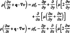
For a Newtonian fluid the stress components т, у are given by Eq. (1.10), and by substituting them into Eqs. (1.26a-c), the Navier-Stokes equations are obtained:

(/ = 1, 2, 3)

image13

and in cartesian coordinates:

FIGURE 1.9
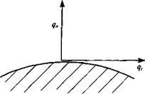
image14Direction of tangential and normal velocity com­ponents near a solid boundary.

image15"image16dy> (1.27b)

(1.27c)

Typical boundary conditions for this problem require that on stationary solid boundaries (Fig. 1.9) both the normal and tangential velocity components will reduce to zero:

q„-0 (on solid surface) (1.28a)

q, = 0 (on solid surface) (1.28b)

The number of exact solutions to the Navier-Stokes equations is small because of the nonlinearity of the differential equations. However, in many situations some terms can be neglected so that simpler equations can be obtained. For example, by assuming constant viscosity coefficient p, Eq. (1.27) becomes

p(^ + 4 • Vq) = pf – Vp + juV2q +1 V(V • q) (1.29)

Furthermore, by assuming an incompressible fluid (for which the continuity equation (Eq. (1.23)) is V • q = 0), Eq. (1.27) reduces to

p(|j + q-Vq) = pf~Vp+ pV2q (1-30)

For an inviscid compressible fluid:

^ + q • Vq = f — — (1.31)

at p

This equation is called the Euler equation.

DIFFERENTIAL FORM OF THE FLUID DYNAMIC EQUATIONS

,явд a

+7 Te+q*Tx

CL*,

FIGURE 1.10

Cylindrical coordinate system.


In situations when the problem has cylindrical or spherical symmetry, the use of appropriate coordinates can simplify the solution. As an example, the fundamental equations for an incompressible fluid with constant viscosity are presented. The cylindrical coordinate system is described in Fig. 1.10, and for this example the г, в coordinates are in a plane normal to the x coordinate. The operators V, V2 and D/Dt in the г, в, x systems are (see Pai,14 p. 38 or Yuan,12 p. 132)


DIFFERENTIAL FORM OF THE FLUID DYNAMIC EQUATIONS

(1.32)


(1.33)

(1.34)


D_

Dt


The continuity equation in cylindrical coordinates for an incompressible fluid then becomes


dqr ldqe, dqx | qr_Q dr г дв Эх г

The momentum equation for an incompressible fluid is r direction:


(1.35)


(Dqr q\_. dP. Jrfl„ 2 3?e

PVN~Т) = + (L36)


в direction:


x direction:


p£3±=pf il+p

У Dt И Эх И 4


image17image18image19image20

DIFFERENTIAL FORM OF THE FLUID DYNAMIC EQUATIONS

image21

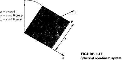
A spherical coordinate system with the coordinates г, d, <p is described in Fig. 1.11. The operators V, V2 and D/Dt in the г, d, <p system are (Karamcheti,15 chapter 2, or Yuan,12 p. 132)

Подпись:„ / э ід і э

^ a >®e aa ’ ®,p a a )

dr r da r sin в dtp!

image22(2d 1 d ( . d 1 Э2

V dr) + r2 sin в dd ,n dd) + r2 sin2 в dip2

R = l + a 3 Яв 3 3

Dt dt "r dr r dd r sin d d<p

The continuity equation in spherical coordinates for an incompressible fluid becomes (Pai,14 p. 40)

1 d(r2qr) 1 d(ge sin d) | 1 Q

r dr sin d dd sin d dqp

The momentum equation for an incompressible fluid is (Pai,14 p. 40): r direction :

Щг q% + q2e. f _$P

dr

. Mr 2 9qe 2qe cot в 2 dqv

+ ———— – —— (1.43)

d direction :

(Ще, ЧгЧв ЧІcot в _ „г 1 дР р(-5Г + ~ 7 )~р1‘~~гэв

( 2 2 dqr qe 2 cos d dqЛ

+ ^ r2 dd r2sin2 0 r2sin20 3<p/

FIGURE 1.12
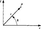
image23Two-dimensional polar coordinate system.
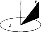
(p direction:

Dq<r qvqr qeqv cot fl ^ і Ф

£)/ /• r / ^v r sin 0 dtp

(V2 Чя> . 2 дЯг. 2 cos e dqe

‘4v^ r2 sin2 O r2 sin 0 3® r2 sin2 в dw ) (145)

When a two-dimensional flow field is treated in this text, it will be described in either a cartesian coordinate system with coordinates x and z or in a corresponding polar coordinate system with coordinates r and в (see Fig. 1.12). In this polar coordinate system, the continuity equation for an incompressible fluid is obtained from Eq. (1.35) by eliminating dqx/dx and the r – and 0-momentum equations for an incompressible fluid are identical to Eqs.

(1.36) and (1.37), respectively.

INTEGRAL FORM OF THE FLUID DYNAMIC EQUATIONS

To develop the governing integral and differential equations describing the fluid motion, the various properties of the fluid are investigated in an arbitrary control volume that is stationary and submerged in the fluid (Fig. 1.8). These properties can be density, momentum, energy, etc., and any change with time of one of them for the fluid flowing through the control volume is the sum of the accumulation of the property in the control volume and the transfer of this property out of the control volume through its boundaries. As an example, the conservation of mass can be analyzed by observing the changes in fluid density p for the control volume (c. v.). The mass mc v within the control volume is then:

mc. v. = [ pdV (1.13)

•’C. V.

where dV is the volume element. The accumulation of mass within the control volume is

Подпись: dmcv dt image11(1.13a)

The change in the mass within the control volume, due to the mass leaving (mout) and to the mass entering (min) through the boundaries (c. s.) is:

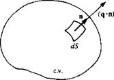
Подпись: FIGURE 1.8 A control volume in the fluid.
image12

mOM – min = p(q • n) dS (1.14)

where q is the velocity vector (к, v, w) and pq • n is the rate of mass leaving across and normal to the surface element dS (n is the outward normal), as shown in Fig. 1.8. Since mass is conserved, and no new material is being produced, then the sum of Eq. (1.13a) and Eq. (1.14) must be equal to zero:

<ii5>

Equation (1.15) is the integral representation of the conservation of mass. It simply states that any change in the mass of the fluid in the control volume is equal to the rate of mass being transported across the control surface (c. s.) boundaries.

In a similar manner the rate of change in the momentum of the fluid flowing through the control volume at any instant d(mq)cv,/dt is the sum of the accumulation of the momentum per unit volume pq within the control volume and of the change of the momentum across the control surface boundaries:

=11. m dv+{, ‘’ч(ч • ■>dS <L l6>

This change in the momentum, as given in Eq. (1.16), according to Newton’s second law must be equal to the forces E F applied to the fluid inside the control volume:

Подпись:d(mq)c v „

The forces acting on the fluid in the control volume in the xt direction are either body forces pft per unit volume, or surface forces лут, у per unit area, as discussed in Section 1.4:

(EfW pfdV+( n, TvdS (1.18)

‘ ‘ І «ЧГ. І». Jc. S.

where n is the unit normal vector that points outward from the control volume.

By substituting Eqs. (1.16) and (1.18) into Eq. (1.17), the integral form of the momentum equation in the і direction is obtained:

~ f pq, dV + f pq,(q – n)dS= [ pfidV+ f прц dS (1.19)

*c. v. ^c. s. Л:.V. *4r. s.

This approach can be used to develop additional governing equations, such as the energy equation. However, for the fluid dynamic cases that are being considered here, the mass and the momentum equations are sufficient to describe the fluid motion.

FORCES IN A FLUID

Prior to discussing the dynamics of fluid motion, the types of forces that act on a fluid element should be identified. Here, forces such as body forces per unit mass f, and surface forces that are a result of the stress vector t will be considered. The body forces are independent of any contact with the fluid, as in the case of gravitational or magnetic forces, and their magnitude is proportional to the local mass.

To define the stress vector t at a point, consider the force F acting on a planar area 5 (shown in Fig. 1.4) with n being an outward normal to S. Then

‘"Sid)

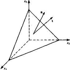
In order to obtain the components of the stress vector, consider the force equilibrium on an infinitesimal tetrahedral fluid element, shown in Fig. 1.5. According to Batchelor11 (p. 10) this equilibrium yields the components in the JC], x2, and x3 directions,

= X топ/ і = 1. 2, 3 (1.7)

image5 Подпись: FIGURE 1.4 Force F acting on a surface S.

/=і

where the subscripts 1, 2 and 3 denote the three coordinate directions. A similar treatment of the moment equilibrium results in the symmetry of the stress vector components so that т/; = r;i.

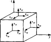
These stress components xtj are shown schematically on a cubical element in Fig. 1.6. Note that r,, acts in the xt direction on a surface whose outward normal points in the x, direction. This indicial notation allows a simpler presentation of the equations and the subscripts 1, 2, and 3 denote the coordinate directions x, y, and z, respectively. For example,

Xi=X x 2 = y x3 = z

Подпись: FIGURE 1.5 Tetrahedral fluid element.
image6

Яг = и Я2 = У q3=w

The stress components shown on the cubical fluid element of Fig. 1.6. can be

FORCES IN A FLUID

image7

FIGURE 1.6

Stress components on a cubical fluid element.

= *,,

Подпись: Txу 1 Til *12 *13 Zyx Tyy 4=l *21 *22 *23 rzx TZy w *31 *32 *33 Подпись: (1.8)

summarized in a matrix form or in an indicial form as follows:

Also, it is customary to sum over any index that is repeated, such that

з

2 *</«, = Tijfij for і = 1,2,3 (1.9)

i=i

and to interpret an equation with a free index (as і in Eq. (1.9)) as being valid for all values of that index.

Подпись: dq, dx image9 Подпись: (1.10)
image8

For a Newtonian fluid (where the stress components r,7 are linear in the derivatives dqj dxj), the stress components are related to the velocity field by (see, for example, Batchelor,11 p. 147)

i=j

i*j

FORCES IN A FLUID Подпись: (o

where ju is the viscosity coefficient, p is the pressure, the dummy variable к is summed from 1 to 3, and dq is the Kronecker delta function defined by

When the fluid is at rest, the tangential stresses vanish and the normal stress component becomes simply the pressure. Thus the stress components become

-p

0

°

0

-P

°

(1.11)

0

0

-PI

image10 Подпись: FIGURE 1.7 Flow between a stationary (lower) and a moving (upper) plate.

Another interesting case of Eq. (1.10) is the one-degree-of-freedom shear flow between a stationary and a moving infinite plate with a speed 14, (shown in Fig. 1.7), without pressure gradients. This flow is called Couette flow (see,

for example, Yuan,12 p. 260) and the shear stress becomes

Подпись: (1.12)Эи ції a,

x” = flTz = – T

Since there is no pressure gradient in the flow, the fluid motion in the x direction is entirely due to the action of the viscous forces. The force F on the plate can be found by integrating txz on the moving upper surface.

PATHLINES, STREAK LINES, AND STREAMLINES

Three sets of curves are normally associated with providing a pictorial description of a fluid motion: pathlines, streak lines, and streamlines.

Pathlines. A curve describing the trajectory of a fluid element is called a pathline or a particle path. Pathlines are obtained in the Lagrangian approach by an integration of the equations of dynamics for each fluid particle. If the velocity field of a fluid motion is given in the Eulerian framework by Eq. (1.4) in a body-fixed frame, the pathline for a particle at P0 in Fig. 1.1 can be obtained by an integration of the velocity. For steady flows the pathlines in the body-fixed frame become independent of time and can be drawn as in the case of flow over the airfoil shown in Fig. 1.1.

Streak lines. In many cases of experimental flow visualization, particles (e. g., dye, or smoke) are introduced into the flow at a fixed point in space. The line connecting all of these particles is called a streak line. To construct streak lines using the Lagrangian approach, draw a series of pathlines for particles passing through a given point in space and at a particular instant in time, connect the ends of these pathlines.

Streamlines. Another set of curves can be obtained (at a given time) by lines that are parallel to the local velocity vector. To express analytically the equation of a streamline at a certain instant of time, at any point P in the fluid, the velocity* q must be parallel to the streamline element dl (Fig. 1.3). Therefore, on a streamline:

image4

Bold letters in this book represent vectors.

If the velocity vector is q = (a, v, w), then the vector equation (Eq. (1.5)) reduces to the following scalar equations:

Подпись: (1.6)w dy – v dz = 0 и dz —wdx = 0 v dx — и dy = 0

or in a differentia] equation form:

Подпись: (1.6a)dx _dy _dz и v w

In Eq. (1.6a), the velocity (a, v, w) is a function of the coordinates and of time. However, for steady flows the streamlines are independent of time and streamlines, pathlines, and streak lines become identical, as shown in Fig. 1.1.