Category AERODYNAMICS

Linear Source/Quadratic Doublet Method

For this example, too, the approach of Section 11.3 is used and a combination of linearly varying strength sources and vortices will be distributed on the solid

image474

FIGURE 11.34

Doublet distribution near the trailing edge of an airfoil.

boundaries 5 (Fig. 11.34) and the vortex distribution is replaced by a quadratic doublet distribution. Following Section 11.3.1 the velocity potential within the volume enclosed by S is selected as Ф* = Фх and the boundary condition at each collocation point is reduced to the form given by Eq. (11.62):

S Bt°i + 2 с№ = 0 (11.62)

i=i j=i

where Ni is the number of singularity strength parameters. In this section a solution based on this equation using linearly varying source and quadratic doublet distributions will be established. The wake, however, will be modeled by a constant-strength doublet as shown in Fig. 11.34. Now, to develop the method of solution, let us follow the basic six step procedure.

Selection of singularity element. The potential at an arbitrary point P due to a linearly varying strength source element with the edge values of or oj+l was derived in the previous section and is given by Eq. (11.110):

Ф-? = PHILS (<jj, aj+ux, z, Xj, Zj, xj+l, zj+l) (11.110)

Similarly, the potential at point P due to a quadratic doublet distribution element where the doublet strength (in panel local coordinates) varies as

fl(x) = Ho + jUi-t + ц2х2

is obtained by combining Eqs. (10.28), (10.59), and (10.80):

+ ^ (x2 – z2)(6i — в2) — xz In —f + z(xx – x2) panel coordinates (11.127) 2jtL r J
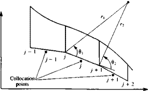
image475 Подпись: FIGURE 11.35 Nomenclature for a quadratic doublet panel element.

where the variables r,, r2, ви and в2 are shown in Fig. 11.35.

When the point P is on the element (z = 0±, xl <x <x2) then this reduces to a combination of Eqs. (10.31), (10.64), and (10.84):

Ф(дг, 0±) = т(^ + ^ j panel coordinates (11.128)

Using the transformation of Eq. (11.23a) (from global to panel coordin­ates) and the above equations for the velocity potential an influence subroutine for the quadratic doublet element can be formulated such that

Ф

Ф" I

фй І = PHIQD [О*, /г,, fi2)j, x, z, xj, zjt xj+1, zj+i] (11.129)

ФC) D

This subroutine computes the potential at a point P due to the jth panel and the superscripts ( )“, ( )b and ( )c represent the panel influence contributions due to the terms in Eq. (11.127) multiplied by ц0, цх, and ц2, respectively. The increment in the potential at point P is therefore the sum of these three terms:

ф = фа + ф’’ + фс (11.130)

It is assumed that these three components of the velocity potential are automatically computed by this subroutine.

Discretization of geometry. The N + 1 panel corner points and N collocation points are generated in a manner similar to the previous examples (see Fig.

11.18) . In this case of the internal Dirichlet boundary condition the collocation points must be placed inside the body. This small inward displacement of the collocation point can be skipped if the panel self induced influence is specified in a separate formula.

Linear Source/Quadratic Doublet Method
image476

Influence coefficients. The increment in the velocity potential at collocation point і due to a quadratic doublet element is computed by using Eq. (11.129) (note that a unit strength was assigned to all three doublet distribution coefficients Mo> Mi and ц2)-

For example, calculating the velocity potential increment by this formula for the first collocation point due to the first panel yields

(ФіМо + ф? і“і + фіМз)і = ЯпМої + Ь uMii + СцМіг

Here the first subscript of the doublets is used as the doublet parameter counter (0, 1, and 2) while the second subscript is the influencing panel counter. Similarly, for the coefficients a, b, and c the first counter is the collocation counter and the second is the influencing panel counter. The potential at this collocation point due to all the doublet panels is

фт = (fluMoi + bnMii + СцМ 21) + (аігМо2 + 612M12 + сі2М2г)

+ • • • + (ДшМолі + blN(iN + cwp2iv) + wPw (11.131)

where nw is the constant-strength wake doublet element (as in Section 11.3.1) and Axw is the wake influence coefficient which can be calculated by using Eq.

(11.66) . The strength of this wake doublet element (modeled by a constant strength doublet panel as shown in Fig. 11.34) is set by applying the Kutta condition at the trailing edge and is give by Eq. (11.118):

Mw = Mu — Ml (11.132)

where Mu and Ml are the upper and lower panel doublet strengths at the trailing edge, respectively.

Equations (11.131) for the potential can be formulated for each colloca­tion point, resulting in N equations (for N panels) with 3N unknown (Mo, Мі» М2)/ and one more unknown, which is the wake doublet strength fiw. Additional equations can be obtained by requiring that the doublet distribution and its gradient will be continuous between neighboring elements. Applying this to the point between the yth and the (/ + l)th panel for the doublet strength results in

Mo/ + Ml/ Асу + М2/(ДС/)2 = Mo. z+1 (11-133fl)

and for the doublet gradient in

Мі/ + 2Мг/ ДCj = Mi,/+i (И-133*)

where A Cj is the panel length. Equations (11.133a and b) can be applied to all panel corner points, excluding the trailing edge, and thereby result in IN -2 equations. The last three equations are found as follows.

1. Equation (11.1336) can be applied at the trailing edge, so that the upper and lower doublet gradients will be equivalent:

Miai T 2мглг Дслі— M11 (11.134)

2. The Kutta condition is specified at the trailing edge by using Eq. (11.132).

Mw = MoN + Ml N Д CN + М2Лі(ДСЛі)2 — Мої (11.135)

3. The last “missing” equation can be obtained by specifying the Ф* = Ф* Dirichlet boundary condition (Eq. (11.62)) on an additional point inside the body. This equation will have the form of the regular N boundary conditions (e. g., as in Eq. (11.131)) and for best results it needs to be
specified near the trailing edge (e. g., on the camberline toward the trailing edge, inside a thick airfoil, or between the upper and lower trailing edge collocation points).

Establish RHS vector. The boundary condition given by Eq. (11.62) is specified at the N + 1 collocation points and the strength of the sources will be specified by using Eq. (11.61) (note that in this case the panel edge source values Oj are evaluated at the panel edges).

a; = n,-Q» (11.61)

Since the source contribution to the velocity potential is now known, the potential due to all the N panels (with N + 1 panel edge source values) can be computed by using Eq. (11.120) such that

N

RHS, = – ‘Z PHILS (Oj, oj+x, xh zh xj, Zj, xj+1, z,+1) (11.120)

y=i

The right-hand side vector RHS, is now evaluated at the N collocation points plus at the (N + l)th point (which was selected inside the body and near the trailing edge).

Solve Equations. At this point it is possible to establish N + 1 equations based on the boundary condition (Eq, (11.62)) plus two equations based on the trailing edge conditions (Eqs. (11.134) and (11.135)) and they will have the following form:

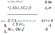
Подпись: A*2 N №w/ Подпись:Я 11^11C11 fl21^21c21

аЛ! +1,1 ^ ЛМ-1,1+1,1

Подпись: 0, -1, -1, 0

о, 0

RHS,

Подпись: (11.136)
image478

rhs2

In this equation the matrix will have 3N + 1 columns (same as the ц vector) and N + 3 rows (same as the RHS vector). The additional 2(N – 1) equations
can be obtained by using Eqs. (11.133-11.135). However, from the computa­tional point of view it is desirable to reduce the influence matrix size, which can be done by substituting the above equations backward while calculating the influence matrix.

It is possible to rearrange Eqs. (11.133a and b) to create a regression formula such that

2

f*u = (/*o,/+i – Hot) – Hi. j+i (11.137a)

^ = 2^с-^1,]+1~iU, y) (11.137b)
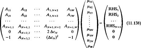
image479

Using these regression equations, all july and y.2j can be eliminated (by performing column operations on the matrix), excluding the last two (nXN and H2n)- These algebraic operations can be performed automatically when assembling the matrix coefficient and will reduce Eq. (11.136) to the form

where now we have N + 3 equations with N + 3 unknowns /Xoi, jUo2,. . . , Hon> Pin, Pin, Hw and AXj are the new coefficients obtained after the resubstitution process.

Solve equations. Solution of the full-matrix equation (Eq. (11.138)) with N + 3 unknown values цк can be obtained by standard matrix solvers. Then the local panel doublet distribution can be obtained by using the same regression formulation that was used to reduce the number of columns in the influence coefficient matrix.

Calculation of pressures and loads. Once the values of the doublet parameters {fxoi, |Uo2. . • • , Ho> Hin> 1*2n) are known, the panel doublet distribution can be calculated. Then the perturbation velocity at each collocation point can be calculated by using the tangential derivative of the doublet at the panel center and the total tangential velocity becomes

Подпись:Qi, = Qt„ + (му + 2^2i~y)

and the pressure coefficient can be calculated by using Eq. (11.18). The lift and pitching moment of the panel can be obtained by using the method described by Eqs. (11.78-11.80).

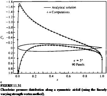
A computer program based on the quadratic doublet is presented in Appendix D and the formulation of the doublet only method is very similar to this one. The pressure coefficients computed with this method for the airfoil of Section 6.6 at an angle of attack of 5° are very similar to the data presented in Fig. 11.31.

METHODS BASED ON QUADRATIC DOUBLET DISTRIBUTION (USING THE DIRICHLET B. C.)

To demonstrate some of the techniques needed for higher-order methods, the linearly varying elements were used in the previous section. The last method to be tested then should be a linearly varying strength vortex panel-based method using the Dirichlet boundary condition. However, such a linearly varying vortex element is equivalent to a quadratic doublet distribution, which will be used to formulate the next two methods.

Also, for the constant strength singularity distribution based elements for N panel elements, N boundary condition based equations were constructed. Combined with the Kutta condition a set of N + 1 algebraic equations were obtained, including the last unknown, which was the wake doublet strength Hw – For higher-order methods, the number of unknowns increase linearly with the order of approximation and, therefore, additional equations must be specified. In the case of the linear methods, N — 1 equations (-1 since the trailing edge point is excluded) were obtained by equating the neighbor panel strengths, which is equivalent to requiring a continuous singularity distribution strength. In this section a generic approach is provided to obtain the additional equations that are needed as the order of approximation for the singularity strength distribution increases. Usually these equations are based on require­ments such as smooth first, second, and higher derivatives at the panel corner point between two neighbor panels, but there are different methods of “obtaining” these additional equations, which can be optimized for certain problems. Therefore, the approach presented here is mainly to demonstrate the method, but improvement of these methods to tailor them for specific problems is encouraged.

Linear Doublet Method

The method of the previous section can be further simplified by equating the source strengths to zero in Eq. (11.60). The value of the constant for the internal potential is selected to be zero and consequently the boundary condition describing the internal potential (Eq. (11.60)) reduces to

!сЛ + Ф. = 0 (11.81)

;=i

where Л/, is the number of singularity strength parameters and

Ф„ = LLx + W„z (11.82)

Again, note that now ju will represent the potential jump from zero to Фи on the boundary (see Fig. 11.26) and therefore Ф„ is the local total potential (whereas in the previous example ц was the jump in the perturbation potential only).

Equation (11.81) can be specified at each collocation point inside the body, providing a linear algebraic equation for this point. The steps toward establishing such a numeric solution are very similar to those of the previous method.

Подпись: Ф ф“ фь Linear Doublet Method Подпись: (11.116)

Selection of singularity element. The potential at an arbitrary point P due to the y’th linearly varying strength doublet element with the two edge values of yt, and ju/+1 is given by Eq. (11.116):

Recall that the superscripts ( )“ and ( )b represent the panel influence contributions due to the leading and trailing doublet strengths, respectively.

Discretization of geometry. The N + 1 panel corner points and N collocation points are generated in a manner similar to the previous examples (see Fig.

11.18) . In this case of the internal Dirichlet boundary condition the collocation points must be placed inside the body. This small inward displacement of the collocation point can be skipped if the panel self induced influence is specified in a separate formula.

Influence coefficients. The influence of this doublet panel is calculated exactly as in the previous section. The velocity potential at each point is the sum of all the individual panel influences and, for example, for the first panel is given by

Eq. (11.117):

фді = (Ф? іМі + Фи^г) + (Ф?2^2 + ФЇгМз)

Н—– 1-(Фїл^л/+ Філг/*л/+і) + Фiwl*w (11.117)

where fiw is the constant-strength wake doublet element (as in Section 11.3.1). The strength of this wake doublet element is set by applying the Kutta condition at the trailing edge and is given by Eq. (11.118).

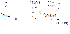
Defining the influence coefficients c, y as in the previous section the following N + 1 influence relations and the (N + 2)th Kutta condition can be summarized in a matrix as in Eq. (11.119):

image470

(11.123)

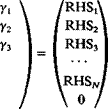
Establish RHS vector. The second term in this equation is known and can be transferred to the right-hand side of the equation. The RHS vector then becomes

image471Подпись: (11.24)RHSi
RHS2

|RHS„+I|
0

and the Ф^ term is calculated by using Eq. (11.82).

Solve equations. Substituting the influence coefficients of the doublets and the

image472

RHS vector into the boundary condition of Eq. (11.81) we get

Linear Doublet Method

(11.125)

In the case that both of Eqs. (11.118) and (11.118a) are applied at the trailing edge then the boundary condition is specified only at the N collocation points (see previous section). Consequently with the use of Eq. (11.119a) the equations to be solved become

image473

(11.125a)

Either of these full-matrix equations with N + 2 unknown values ju* can be solved by standard matrix solvers. Note that in this case (compared to Eq. (11.121)) the doublet represents the jump in the total potential (and not the perturbation only).

Calculation of pressures and loads. Once the values of the doublet parameters (fiu , nN+i) are known, the tangential velocity component at each colloca­tion point can be calculated by differentiating the local potential. For example, such a two-point formula is

g,. = ^— ^ (11.126)

‘ xi+l-xj

and the pressure coefficient can be calculated by using Eq. (11.18). The lift and pitching moment of the panel can be obtained by using the method described by Eqs. (11.78-11.80).

This method seems to involve less numerical calculations than the equivalent linear doublet/source method and therefore will require somewhat less computational time. (A computer program based on this method is presented in Appendix D, Program No. 9.)

LINEARLY VARYING SINGULARITY STRENGTH METHODS (USING THE DIRICHLET B. C.)

In this section linearly varying strength doublet and source elements will be used to formulate methods based on the Dirichlet boundary condition. Since a linear vortex distribution is “equivalent” to a quadratic doublet distribution (which will be described in Section 11.6), such vortex methods are not presented here.

11.5.1 Linear Source/Doublet Method

LINEARLY VARYING SINGULARITY STRENGTH METHODS (USING THE DIRICHLET B. C.) Подпись: (11.62)

For this example, the approach of Section 11.3 is used and a combination of linearly varying strength sources and doublets will be distributed on the solid boundaries S (Fig. 11.32). Following Section 11.3.1 the velocity potential within the volume enclosed by S is selected as Ф(* = Фос and the boundary condition at each collocation point is reduced to the form given by Eq. (11.62):

where Ni is the number of singularity strength parameters. To establish a solution based on this equation using linearly varying singularity distributions, let us follow the basic six-step procedure.

Selection of singularity element. The potential at an arbitrary point P (not on the surface) due to a linearly varying strength source o(x) = a0+ o, x was

Linear-strength singularity element model for a closed body.

derived in Eqs. (10.14) and (10.47) (in the panel coordinate system) and is

Подпись: £i_ An Подпись: x — X, LINEARLY VARYING SINGULARITY STRENGTH METHODS (USING THE DIRICHLET B. C.) Подпись: ■xl Подпись: -In r + 2xz{Q2 - &i) — x(x2 -xt)j panel coordinates (11.108)

Ф = -7^[(лг -*0 In r – (x – x2) In r + 2z(d2 – 0,)] 4 Л

LINEARLY VARYING SINGULARITY STRENGTH METHODS (USING THE DIRICHLET B. C.)
panel coordinates (11.108a)

Подпись: (11.109) (11.109a) Using the transformation of Eq. (11.23a) (from panel to global coordin­ates and back) and the above equations for the velocity potential, a subroutine (e. g., PHILS) can be formulated. From the computational point of view it is more useful to evaluate the panel influence based on its edge values. Since the source values are assumed to be known, based on Fig. 11.30 we can write for the /th panel

o0, = Oj

Подпись:-2b

where ajt oj+1 are the source values at the panel’s two edges. So based on the formulas for the velocity potential (Eqs. (11.108) and (11.108a), including the transformation between the panel and global coordinate systems as in Eq. (11.23a)) and on the substitution of Eqs. (11.109) and (11.109a) the influence subroutine for the linearly varying source is defined as

Ф5 = PHILS (oj, oj+1, z, Xj, Zj, xj+u z;+1) (11.110)

Here the potential due to the /’th element is a function of the coordinates and the panel edge singularity strengths.

Next, the potential at an abitrary field point P due to the linearly varying strength doublet fi(x) = fi0 + fitx is obtained by combining Eqs. (10.28) and

(10.59) :

panel coordinates

(11.111)

When the point P is on the element (z = 0±, xx <x <x2) then this reduces to the results of Eqs. (10.31) and (10.64):

Ф(х, 0±) = + panel coordinates (11.111a)

Similarly to the source case, a substitution for the doublet strength parameters ц0 and /хъ in terms of the panel edge values, gives

Подпись:Mo, = My

— ^+1 ~ Iі >

Mi, —

*y+i ~ Xj

These equations combined with Eq. (11.111) result in

– **i+1—Г2x(8/+} – в/) + z ln^1] panel coordinates (11.113) QjzyXj^ і xp L fj J

and now the panel influence depends on the leading and trailing singularity strengths njt nj+1. It is useful to rearrange this equation so that the first term Ф" is a function of jU/ and the second part Ф* is a function of Thus Eq. (11.113) is rewritten as

ф = ф“ + ф* (11.113a)

ф*> = –

– ^’+l—— [jc(0;+i — 8.) + ^ In -^1 panel coordinates

2 iTT +1 j L 2 Tj j

(11.115)

Again, using the transformation of Eq. (11.23a) (from global to panel coordinates) and the above equations for the velocity potential an influence subroutine can be formulated such that

r

Ф” = PHILD (fij, fij+u x, z, Xj, Zj, xj+1, zi+l) (11.116)

WJd

These subroutines (for the source and doublet elements) compute the potential at a point P due to the ;th panel and superscripts ( )° and ( )b in the case of the doublet element represent the panel influence contributions due to the leading and trailing doublet strengths, respectively.

Discretization of geometry. The N + 1 panel corner points and N collocation points are generated in a manner similar to the previous examples (see Fig.

11.18) . In this case of the internal Dirichlet boundary condition the collocation points must be placed inside the body. This small inward displacement of the
collocation point can be skipped if the panel self induced influence is specified in a separate formula.

Influence coefficients. The increment in the velocity potential at collocation point і due to a linearly varying strength doublet on panel j is computed by using Eq. (11.116):

image467(

Note that the contribution due to the panel edge singularity strengths is automatically computed (as in Eqs. (11.114) and (11.115)). Thus, for the first collocation point the doublet influence due to the first panel is

Ф11М1 + ФиМг

and that due to all the doublet panels is

Фоі = (Ф? іМі + ФпМг) + (Ф?2|И2 + Ф?2Мз)

+ • • • + (Ф + ФшМлч-і) + ФпуМи’ (11-117)

where nw is the constant-strength wake doublet element (as in Section 11.3.1). The strength of this wake doublet element is set by applying the Kutta condition at the trailing edge such that

Подпись: (11.118)Mw — Млі+ 1 Ml

It is possible to add additional conditions at the trailing edge such as the requirement that the tangential velocity components on the upper and lower surfaces will be equal (or the upper and lower doublet gradients will be equal and opposite in sign). In terms of the four nearest (to the trailing edge) corner-point doublet values this condition becomes

Подпись: (11.118a)Mi М2— Mn Млм-і

Equation (11.117) for the potential can be formulated for each colloca­tion point, resulting in N equations (for N panels). But a closer examination of the problem reveals that at this phase we have N equations with N + 2 unknowns jUj, . . . , juN+1, іuw. An additional equation is obtained by specifying the Kutta condition at the trailing edge (Eq. (11.118)). The last “missing” equation can be obtained by specifying the Ф* = Ф» Dirichlet condition on an additional point inside the body. This equation will have the form of the regular N boundary conditions (e. g., as in Eq. (11.62)) and for best results it needs to be specified near the trailing edge (e. g., on the camberline, inside a thick airfoil, or between the upper and lower trailing edge collocation points).

To construct the influence coefficient matrix, the potential at any point inside the body due to the doublet distribution can be expressed in terms of the influence coefficients cljt as in Eq. (11.62), such that the first term in each row

Подпись: c, LINEARLY VARYING SINGULARITY STRENGTH METHODS (USING THE DIRICHLET B. C.)

(as in Eq. (11.117)) is

the (N + l)th term in each row is

ci, N+1 = ®IN

and the last, (N + 2)th, term is the wake contribution:

ci, N+2 = CiW — ®iW

(Since the wake is modeled by a constant-strength doublet panel its influence coefficient is calculated by using Eq. (11.66), which is presented in Section

11.3.1. ) All the other elements will include the influence of the two neighbor

panels:

c, y = Ф,-y_, + Ф?,, i#l, N + l, N + 2

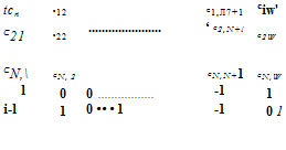
These N + l influence equations and the (N + 2)th Kutta condition can be summarized in a matrix as

Подпись:Подпись: cn C21 I CN+1,1 1 N+l N+2

X X см =

.=i /=i

It is possible to substitute the last equation (the Kutta condition) into the previous equations as was done in Section 11.3.1 and reduce the order of the matrix by one to N + 1 (but for simplicity it is not done for this case).

In this example for the (N + l)th equation, the boundary condition was specified at an additional collocation point inside the body. It is possible to use Eq. (11.118a) instead of this alternative and then Eq. (11.119) will have the form

Подпись:Подпись: t*i  /*2Подпись: f^N+lN+2 N+2

(11.119a)

Here the first N equations are a statement of the doublet contribution to the Dirichlet boundary condition on the N collocation points and the last two equations are forms of the Kutta condition (Eqs. (11.118) and (11.118a)).

Establish RHS vector. The combination of source and doublet distributions of Eq. (11.62) is not unique and as in Section 11.3.1 the strength of the sources will be specified by using Eq. (11.61) (note that in this case the panel edge source values Oj are evaluated at the panel edges):

CTy = ny‘Q» (11.61)

Since the source contribution to the velocity potential is now known, the potential due to all the N panels can be computed by using Eq. (11.110) such that

N

RHS, = – 2 PHILS (a), o/+ux„ z„ xn zjt xl+u z/+,) (11.120)

/=i

The right-hand side vector RHS, is now evaluated at the N collocation points plus at the (N + l)th point (which is needed when using Eq. (11.119) and was selected inside the body and near the trailing edge).

RHS*

Подпись: Сц C12 • * * С1,Л/+1 CW  / C21 C22 . . C2,N+l ^2 W / ^2 CN+1,1 CN+1,2 CN+,N+ CN+1,W IIUN+1 ^ 1 0 0 -1 1 /v LINEARLY VARYING SINGULARITY STRENGTH METHODS (USING THE DIRICHLET B. C.)

Solve equations. Substituting the influence coefficients of the doublets and the RHS vector into the boundary condition (Eq. (11.62)) we get

(11.121a)

Either of these full-matrix equations with N + 2 unknown values цк can be solved by standard matrix solvers.

Calculation of pressures and loads. Once the values of the doublet parameters (Hi, , nN+i) are known, the tangential velocity component at each colloca-

LINEARLY VARYING SINGULARITY STRENGTH METHODS (USING THE DIRICHLET B. C.) Подпись: (11.122)

tion point can be calculated by differentiating the local potential:

image468(11.18)

The lift and pitching moment of the panel can be obtained by using the method described by Eqs. (11.78-11.80).

A computer program based on this method was formulated and the computed pressure coefficients for the airfoil of Section 6.6 at an angle of attack of 5° are very similar to the data presented in Fig. 11.31. The linearly varying strength doublet portion of this method can be found in Program No. 9 in Appendix D.

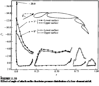
Подпись: c FIGURE 11.33 Effect of angle of attack on the chordwise pressure distribution of a four-element airfoil.
As an additional example, the pressure distribution on a four-element airfoil was calculated by using this method and is presented in Fig. 11.33. Experimental data (which is not presented here) agrees well with these results excluding the large suction peak at the leading edge (which was near Cp = -13 in the experimental data). The effect of an angle of attack change is depicted in

this figure and it seems that mostly the forward elements are affected by such a change.

Linear-Strength Vortex Method

The constant strength vortex method of Section 11.2.3 posed some difficulties which can be corrected by using the linear strength vortex element. To describe the method let us follow the basic six step procedure:

Selection of singularity element. The linearly varying source distribution shown in Fig. 11.29 includes the same nomenclature that is used for the linearly varying strength vortex panel. The velocity components (и, w)p in the
direction of the panel coordinates were obtained in Sections 10.2 and 10.3 (Eqs. (10.39), (10.40), (10.72), and (10.73)):

Подпись: (JC — JC i)2 + z2

p 2л L x—x2 x-xtJ 4л L (x—x2)+ z

Подпись:+ 2x(tan-1 — —– tan-1 —-—) panel coordinates

x — x2 x-x,/J

Yo, (x-Xi )2 + z2 Yix, (x-xt f + z2′,

WD = — -— In ————————- -5————- 5 — —— I — In ——————————- 4? 7 + Ui — X2)

Linear-Strength Vortex Method Linear-Strength Vortex Method Подпись: panel coordinates Подпись: (11.98)

p 4л (jc – jc2)2 + z2 2л 12 (jc – jc2)2 + z2

where the subscripts 1, 2 refer to the panel edges j and j + 1, respectively. As in the case of the linearly varying strength source, it is useful to rearrange these equations in terms of their edge vortex strengths y, and y,+l (see Eqs. (11.88a and b)) and to use the subscripts j and j + 1 instead of 1, 2.

WjVUZM ,nfe!+ * (Г,,. ~ Г,)(* -*y>( _ e)

2л jc;+1 – JCy/ ry 2л{хі+х — jcy)

Linear-Strength Vortex Method Подпись: (11.100)

panel coordinates (11.99)

These two equations combined with the transformation of Eq. (11.23) can be included in a subroutine VOR2DL such that

(

u, w

u“, wa I = VOR2DL (у,, уу+і, xh z„ Xj, zjt xj+u zj+l) (11.101)

Ub, WbJij

where the superscripts ( )° and ( )b represent the contributions due to the leading and trailing singularity strengths, respectively. For simplicity, this procedure is not repeated here but can be obtained simply by taking all terms multiplied by y, in Eqs. (11.99) and (11.100) to produce the ( )“ component and all terms multiplied by y;+1 to produce the ( )b component (as was done in the case of the linearly varying strength source—see Eqs. (11.91) and (11.92)). This decomposition of the velocity components is automatically calculated by Eq. (11.101), and

(u, w) = (ua, wa) + (ub, wft)

Discretization of geometry. The panel cornerpoints, collocation points, and normal vectors are computed as in the previous methods.

Linear-Strength Vortex Method

Influence coefficients. In this phase the zero normal flow boundary condition (Eq. (11.4)) is implemented. For example, the self-induced velocity due to the yth element with a unit strength y, and y;+1, at the first collocation point can be obtained by using Eq. (11.101):

u, w

ua, wa = VOR2DL (y, = 1, Yj+i = l, Xi, zu xt, zjt xJ+1, zj+l) (11.102)

Подпись: ub, wb

v

Similarly to the case of the linearly varying strength source the velocity at each collocation point is influenced by the two edges of the jth panel. Thus, when adding the influence of the j + 1 panel and on, the local self-induced velocity at the first collocation point will have the form

(u, w)i = (u“, wa)nyl + [(іub, wb)n + (ua, wa)l2]y2 + [0Л wb)12 + (ua, H’°),3]y3 + • • • + [(u6, H’b)ljA,_1 + («“, w°)jN]yA, + (ub, wfr)1A, yN+I

This equation can be reduced to a form

(u, w)! = (u, w)11y1 + (m, w)i2y2 + ••• + («, w)1>A,+1 Ys+l such that for the first and last terms

(м, и’),! = (ua, wa)n у, (11.103л)

(и, »v)1>A,+, = (ub, н’*)ш Yn+ (11.103b)

and for all other terms

(u, w)Uj = [(m6, wfr)l y_, + (ua, wa)UjYi (11.103c)

From this point and on the procedure is similar to the linearly varying strength source method. The influence coefficient is calculated when у, = 1 and

a,, = (u, w),., • n, (11.104)

For each collocation point there will be N + 1 such coefficients and unknowns

Yj-

Establish boundary condition (RHS). The free-stream normal velocity com­ponent RHS, is found, as in the case of the discrete vortex (by using Eq. (11.6a)):

RHS, = -(IL, ИУ • (cos ar,, – sin a,)

Solve equations. Specifying the boundary condition for each (i = 1—» N) of the collocation points results in N linear algebraic equations with the unknowns y, (/ = 1 —» N + 1). The additional equation can be found by specifying the Kutta condition at the trailing edge:

Consequently the set of equations to be solved becomes

Подпись:image462a 12

a22

a32

[ dm aN2 1 0 0

The above set of algebraic equations has a well-defined diagonal and can be solved for Yj by using standard methods of linear algebra.

Calculation of pressures and loads. Once the strength of the vortices y, is known, the perturbation velocity at each collocation point can be calculated using the results for a vortex distribution (e. g. Eq. (3.147)):

Q’=(Q, J, + y,Yl+’ (11.106)

image463

and the pressure coefficient can be calculated by using Eq. (11.18):

The lift of the panel can be computed from this pressure distribution or by using the Kutta-Joukowski theorem

image465(11.107)

where Acj is the panel length. The total lift and moment are obtained by summing the contribution of the individual elements (as in Eqs. (11.54) and

Подпись: (11.55)).

A computer program based on this method is presented in Appendix D (Program No. 6) and the computed pressure coefficients for the airfoil of Section 6.6 at an angle of attack of 5° are presented in Fig. 11.31.

LINEARLY VARYING SINGULARITY STRENGTH METHODS (USING THE NEUMANN B. C.)

As an example of higher-order paneling methods using the Neumann boundary condition, the linear source and vortex formulations will be presented. Since the linear doublet distribution is equal to the constant-strength vortex distribution, only the above two methods will be studied. Here the panel surface is assumed to be planar and the singularity will change linearly along the panel. Consequently, the singularity strength on each panel includes two unknowns and additional equations need to be formulated.

11.4.1 Linear-Strength Source Method

The source-only based method will be applicable only to the nonlifting configurations and is considered to be a more refined model than the one based on constant-strength source elements. The basic six step procedure is:

Selection of singularity element. A segment of the discretized singularity distribution on a solid surface segment is shown in Fig. 11.29. To establish a normal-velocity boundary condition based method (see Eq. (11.4)), the induced velocity formulas of a constant and a linear strength source distribu­tion are combined (Eqs. (10.17) and (10.48), and Eqs. (10.18) and (10.49)). The parameters в and r are shown in Fig. 11.29 and the

where the subscripts 1, 2 refer to the panel edges j and j + 1, respectively.

zp +

image457

x

FIGURE 11.29

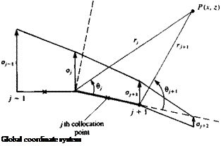
Nomenclature for a linear-strength surface singularity element.

Подпись: Global coordinate system

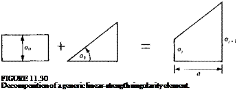
In these equations ct0 and a, are the source strength values, as shown in Fig. 11.30. If the strength of о at the beginning of each panel is set equal to the strength of the source at the end point of the previous panel (as shown in Fig. 11.29), a continuous source distribution is obtained. Now, if the unknowns are the panel edge values of the source distribution (ojt aj+1, . . . as in Fig. 11.29) then for N surface panels on a closed body the number of unknowns is N + 1. The relation between the source strengths of the elements shown in Fig. 11.30 and the panel edge values is:

af = a0 (11.88a)

Oj+i = o0 + axa (11.88b)

Подпись: FIGURE 11.30 Decomposition of a generic linear-strength singularity element.

where a is the panel length and for convenience the induced velocity equations are rearranged in terms of the panel-edge source strengths о) and ay+1 and the

subscripts 1, 2 are replaced with the j and / + 1 subscripts, respectively:

<?/(*/+1 – Xj) + (g/ + 1 – Oj)(x – Xj) r,

Подпись:4+1

—– 1 – u-z—- —fL + (6І+Л — в,)] in panel coordinates (11.89)

2n ‘*^y+i Гу/ L z j

Подпись: = -±(4Подпись: 7+1

Подпись: 2яхі+1 Xj

Уiti+<’&«-*’> + ((( _„,

/’ r, 2jr(jfy+j – Гу)

in panel coordinates (11.90)

Note that Eqs. (11.89) and (11.90) can be divided into velocity induced by at and by oj+l, such that

(u, w)p = (ua, wa)p + (и*, wb)p (11.91)

LINEARLY VARYING SINGULARITY STRENGTH METHODS (USING THE NEUMANN B. C.) Подпись: (11.926)

where the superscripts ( )° and ( )b represent the contribution due to the leading and trailing singularity strengths, respectively. By rearranging Eqs. (11.89) and (11.90) the ( )° part of the velocity components is

and the ( )b part of the velocity components is

. – ■*<> JL – _L + (9 . „ ,1

LINEARLY VARYING SINGULARITY STRENGTH METHODS (USING THE NEUMANN B. C.) Подпись: (11.92c) (11.92d)

2я{хі+і – Xj) ri+1 2nXj+l-Xj)l z J

Подпись: / u  _ / cos or, w)  -sin 0',- LINEARLY VARYING SINGULARITY STRENGTH METHODS (USING THE NEUMANN B. C.) Подпись: (11.23)

To transform these velocity components back to the x-z coordinates, a rotation by the panel orientation angle a, is performed as given by Eq. (11.23):

This procedure can be included in an induced velocity subroutine SOR2DL (where L stands for linear) which will compute the velocity (и, w) at an arbitrary point (x, z) in the global coordinate system due to the yth element.

u, w

Подпись: (11.93)ua, wa I = SOR2DL(a/( oj+u x, z, Xj, Zj, x.+1, zj+1)

The four additional velocity components (h“, wa, ub, wb) will be a byproduct of subroutine SOR2DL.

Discretization of geometry. The panel cornerpoints, collocation points, and normal vectors are computed as in the previous methods.

Influence coefficients. In this phase the zero normal flow boundary condition is implemented. For example, the velocity induced by the jth element with a unit strength Oj and cry+1, at the first collocation point can be obtained by using Eq.

(11.93) :

(

u, w

ua, wa = SOR2DL(ay = 1, aj+^ = , xx, zu xh zy, xj+u zj+l) (11.93a) ub, wb I ij

where the superscripts ( )e and ( )* represent the contributions due to the leading and trailing singularity strengths, respectively. This example indicates that the velocity at each collocation point is influenced by the two edges of the y’th panel. Thus, when adding the influence of the j + 1 panel and on, the local induced velocity at the first collocation point will have the form

(и, w)! = (ua, Wa)na, + [(ub, w6)!! + (m“, H’a)12]a2 + [(иь, wb)l2 + (u“, *va)13]a3

+ • • • + [(иЬ, Wb)i, N-l + («“, *v<,)in]^n + (ub, wb)iNoN+l

This equation can be reduced to a form

(m, w)a = (m, w)!!^ + (m, w)12<t2+ • • • + (u, w)i N+laN+l

such that for the first and last terms

(a, w)„ = K, wOnOj

(11.94a)

(u, h01>;V+1 = (ub, wb)lNoN+1

(11.94b)

and for all other terms

(и, w)hj = [(и*, W’*)1>y_1 + (ua, Wa)hjOj

(11.94c)

From this point and on the procedure is similar to the constant-strength source method. The influence coefficient is calculated when ау = 1 and

aij = (U, W)i, j ■ n,

(11.95)

For each collocation point there will be N + 1 such coefficients and unknowns

Establish boundary condition (RHS). The free-stream normal velocity com­ponent RHSi is found, as in the case of the discrete source (by using Eq. (11.6b)), at the collocation point

RHS, = —1/«, sin a,

Solve equations. Specifying the boundary condition for each (i = —>N)of the collocation points results in N linear algebraic equations with the unknowns (j = 1 —* N + 1). The additional equation can be found by requiring that the flow leaves parallel to the trailing edge, thus

CTj + CT/v+^O (11.96)

Another option that will yield a similar result is to establish an additional collocation point slightly behind the trailing edge and require that the velocity will be zero there (stagnation point for finite-angle trailing edges). Conse­quently the set of equations to be solved becomes

Calculation of pressures and loads. Once the strength of the sources Oj is known, the velocity at each collocation point can be calculated using Eq.

(11.93) and the pressure coefficient can be calculated by using Eq. (11.18).

The formulation presented here allows for the nonlifting body to be “slightly” nonsymmetric. In the case of a symmetric body the number of unknowns can be reduced to N/2 (e. g., to the number of upper surface elements only) by the minor modification presented at the end of Section 11.2.1.

Note that for a closed body the sum of the sources must be zero. However, this condition is not an independent one and cannot be used instead of the additional equation (Eq. (11.96)).

A computer program based on this method is presented in Appendix D (Program No. 5) and the computed pressure coefficients for the airfoil of Section 6.6 result in a pressure distribution similar to that of Fig. 11.19.

Constant-Strength Doublet Method

An even simpler method for lifting airfoils can be derived by setting the source strengths to zero in Eq. (11.60). The value of the constant for the internal potential is selected to be zero (since a choice similar to that of the previous section of Ф, = О» will result in the trivial solution). Consequently the boundary condition describing the internal potential (Eq. (11.60)) reduces to

Ісл + Ф. = 0 (11.81)

i=і

where

Ф* = Uax + W^z (11.82)

Note that now ц will represent the potential jump from zero to Ф„ on the boundary (see Fig. 11.26) and therefore Ф„ is the local total potential (whereas in the previous example fj, was the jump in the perturbation potential only).

Equation (11.81) can be specified at each collocation point inside the body, providing a linear algebraic equation for this point. The steps toward
establishing such a numeric solution are very similar to the previous method:

Selection of singularity element. For this case a constant-strength doublet element is used and the potential at an arbitrary point P (not on the surface) due to a constant-strength doublet is given by Eq. (11.64) and by the routine of Eq. (11.66):

Подпись: (11.66)ЛФл = PHICD (juy, x, z, Xj, zj, xj+u z/+1)

Discretization of geometry. The N + 1 panel comer points and N collocation points are generated in a manner similar to the previous example and a typical grid is shown in Fig. 11.18. Since in this case the internal Dirichlet boundary condition is used the collocation points must be placed inside the body (with a small inward displacement under the panel center—this inward displacement can be skipped if the self-induced influence is specified separately).

image452

Influence coefficients. The increment in the velocity potential at collocation point і due to a unit strength constant doublet element of panel j is given by Eq. (11.68):

The construction of the doublet influence matrix and the inclusion of the Kutta condition (and the wake doublet nw) is exactly the same as in the previous example. Thus, after substituting the Kutta condition (juw = fiN – Ці), the c, y influence coefficients become the atj coefficients (see Eq. (11.70)). Using these results, Eq. (11.81), when specified at each collocation point, will have the form

Подпись: = 0image453(11.83)

image455 image454
Подпись: (11.84)

Establish RHS vector. The second term in this equation is known and can be transferred to the right-hand side of the equation. The RHS vector then becomes

and the Ф„4 term is calculated by using Eq. (11.82).

Solve equations. At this phase the N equations will have the form similar to Eq. (11.73) and can be solved for the N unknown values (ik.

Calculation of pressures and loads. Once the strength of the doublets ft, is known, the potential outside the surface can be calculated based on the principle shown schematically in Fig. 11.26 (but now Ф* = 0). Equation (11.75) is still the basis for calculating the local velocity but now the external potential

TABLE 11.3

Influence matrix for the airfoil shown in Fig. 11.27 using ten panels (a = 5°, constant-strength doublets only, with the Dirichlet boundary conditions)

0.50

0.00

0.01

0.01

0.01

0.01

0.01

0.01

0.04

0.40

0.02“

ft 1

~ 0.81Г

0.00

0.50

0.01

0.01

0.01

0.01

0.02

0.06

0.34

0.04

0.02

ftl

0.49

0.00

0.01

0.50

0.02

0.02

0.03

0.07

0.27

0.08

0.01

0.02

ft 3

-0.08

0.00

0.01

0.02

0.50

0.04

0.08

0.23

0.10

0.03

0.01

0.01

ft*

-0.61

0.00

0.01

0.02

0.06

0.50

0.24

0.12

0.03

0.01

0.00

0.00

f*5

-0.92

0.00

0.01

0.03

0.12

0.24

0.50

0.06

0.02

0.01

0.00

0.00

ft 6

=

-0.91

0.01

0.03

0.10

0.23

0.08

0.04

0.50

0.02

0.01

0.00

-0.01

th

-0.59

0.01

0.08

0.27

0.07

0.03

0.02

0.02

0.50

0.01

0.00

-0.02

ft*

-0.06

0.04

0.34

0.06

0.02

0.01

0.01

0.01

0.01

0.50

0.00

-0.02

ft 9

0.50

0.40

0.04

0.01

0.01

0.01

0.01

0.01

0.01

0.00

0.50

-0.02

M10

0.88

-1.00

0.00

0.00

0.00

0.00

0.00

0.00

0.00

0.00

1.00

-1.00

ftw

0.00

у substituting

ftw = ft 1C

– fit we get

. «4 ^

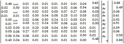
Подпись: 0.48 0.00 0.01 0.01 0.01 0.01 0.01 0.01 0.04 0.43“ fti ” 0.88 -0.02 0.50 0.01 0.01 0.01 0.01 0.02 0.06 0.34 0.06 ftz 0.49 -0.02 0.01 0.50 0.02 0.02 0.03 0.07 0.27 0.08 0.03 fti -0.08 -0.01 0.01 0.02 0.50 0.04 0.08 0.23 0.10 0.03 0.02 ft4 -0.61 0.00 0.01 0.02 0.06 0.50 0.24 0.12 0.03 0.01 0.01 fti -0.92 0.01 0.01 0.03 0.12 0.24 0.50 0.06 0.02 0.01 0.00 ft6 -0.91 0.02 0.03 0.10 0.23 0.08 0.04 0.50 0.02 0.01 -0.01 ft7 -0.59 0.03 0.08 0.27 0.07 0.03 0.02 0.02 0.50 0.01 -0.02 Its -0.06 0.06 0.34 0.06 0.02 0.01 0.01 0.01 0.01 0.50 -0.02 ft9 0.50 0.43 0.04 0.01 0.01 0.01 0.01 0.01 0.01 0.00 0.48 10 0.88

The solution is:

~ft?

-0.6970030"

ft2

-0.3259878

ft3

0.2767572

ft4

0.8576335

fti

1.182451

ftb

1.016438

ft7

0.5045773

ft8

-0.2092538

ft9

-0.8805848

ftw

-1.270261

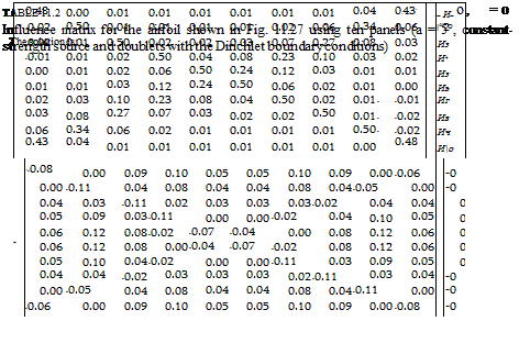
Mw — Mio Mi ~~ —0.5732538

Фм is equal to the local total potential jump ц across the solid surface. Thus, the local external tangential velocity above each collocation point can be calculated by differentiating the velocity potential along the tangential direc­tion and Eq. (11.76) will have the form

Q, t = fli+A I* (1185)

The pressure coefficient and the fluid dynamic loads can be calculated now using the formulation of the previous section (Eqs. (11.77)-(11.80)).

Example 1 Lifting thick airfoil. This constant-strength doublet method is applied to the same problem of the previous section and the resulting pressure distribution with 10 and 90 panels is very close to the results presented in Fig. 11.27. It seems that this method is as effective as the combined source and doublet method and it does not have the matrix multiplication of the source matrix (less numerics). The influence coefficients for the N = 10 panel case are presented in Table 11.3 along with the solution vector. This information is presented since it was found that such data (as in Tables 11.2 and 11.3) is extremely useful in the early stages of code development and validation. Table

11.3 presents the doublet influence coefficients before and after the inclusion of the Kutta condition and also the magnitude of the solution vector цк, which is larger in this case than in the case shown in Table 11.2. This is a result of the unknown fik representing hete the total velocity potential whereas in the

image456

FIGURE 11.28

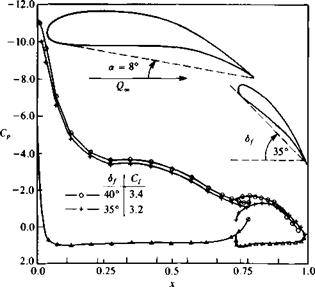
Effect of flap deflection on the chordwise pressure distribution of a two-element airfoil (triangles represent lower surface computational results for both flap angles).

combined doublet/source case the doublet represents the perturbation potential only. Reference 9.2 claims that since the unknown цк are larger in the doublet-only solution, there is a numerical advantage (in terms of convergence for a large number of panels) for using the combined source/doublet method.

Example 2 Two-element airfoil. This method is applied to the two-element airfoil shown in Fig. 11.28. The effect of a 5° flap deflection on the chordwise pressure distribution is shown in the lower part of the figure. In general the effect of flap deflection is to increase the lift of the main planform more than the lift of the flap itself.

A sample student computer program for this method is presented in Appendix D, Program No. 7.

Combined Source and Doublet Method

As the first example for this approach let us use the combination of source and doublet elements on the surface. This means that each panel will have a local source and doublet strength of its own. Since Eq. (11.60) is not unique, either the source or the doublet values must be specified. Here the inner potential is selected to be equal to Ф* and for this case the source strength is given by Eq.

(9.12) as

о^Пу-Q» (11.61)

Since the value of the inner perturbation potential was set to zero (or
(ф* = ф,) Eq. (11.60) reduces to

+ = 0 (11.62)

/=i i=і

This equation (boundary condition) is specified at each collocation point inside the body, providing a linear algebraic equation for this point. The steps toward establishing such a numerical solution are as follows:

Selection of singularity element. The velocity potential at an arbitrary point P (not on the surface) due to a constant-strength source element was derived in the panel’s frame of reference in Eq. (10.19):

Ф = ~ {(* — *1) In [(* – *i)2 + z2] – (де – x2) In [(де – x2)2 + z2]

+ 2z(tan-1 — ———— tan-1 —-—■) | panel coordinates (11.63)

JC — ДС2 ДС-ДСі/J

and that due to a constant-strength doublet element in Eq. (10.28):

Ф = – tan-1 — —————- tan-1 —-— panel coordinates (11.64)

2л L де — дг2 jc-jcJ

These equations can be included in two subroutines that calculate the potential at point (де, z) due to the source and doublet element j:

ДФ* = PHICS (Oj, x, z, xjt Zj, Xj+i, zi+l) (11.65)

ДФа = PHICD (Ц), x, z, xh zjt xj+l, zj+x) (11.66)

These subroutines will include the transformation of the point (де, z) into the panel coordinates (e. g., in Eq. (11.23a)) and it is assumed that these potential increments are expressed in term of the global дс-z coordinates. However, since the influence coefficients depend on view angles and distances between points, the transformation of ДФ back to the global coordinate system can be skipped.

Discretization of geometry. The N +1 panel corner points and N collocation points are generated in a manner similar to the previous example of the constant-strength source (Fig. 11.18). However, now the internal Dirichlet boundary condition will be applied and therefore the collocation points must be placed inside the body. (Usually an inward displacement of 0.05 panel lengths is sufficient—but attention is needed near the trailing edge so that the collocation point is not placed outside the body. In the case where the self-induced influence is specified by a separate formula, then for simplicity the collocation point can be left at the center of the panel surface.)

Influence coefficients. The increment in the velocity potential at collocation point і due to a unit-strength constant source element of panel j is obtained by using Eq. (11.65):

Ьц = PHICS {oj = 1, Xj, z„ xJt Zj, xl+l, z/+1) (11.67)

and that due to the same panel but with a unit-strength doublet:

c(> = PHICD (fij = 1, Xj, Zj, Xj, Zj, xJ+u zj+l) (11.68)

Note that this calculation is simpler than in the case of the velocity boundary condition, which required the computation of two velocity com­ponents and a multiplication by the local normal vector.

Also the influence of the doublet panel on itself (using Eq. (10.31)) is

c„ = § (11.69)

and for the source the self-induced effect can be calculated by using Eq. (11.67).

Determination of the influence of the doublets at each of the collocation points will result in a N x N influence matrix, with N + 1 unknowns (where the wake doublet fiw is the (N + l)th unknown). The additional equation is provided by using the Kutta condition (see Fig. 11.20):

(цг – pN) + pw = 0 (11.36)

Combining this equation with the influence matrix will result in N +1 linear equations for the influence of the doublets:

Jcu

cn…………………

C1N

Cl W

lnA

N+1 N+l

I C21

^22 ………….

C2N

Сг w

1 1*2

X 2 Сц/ij—

……………………..

-=i j=i

I CNl

CAI2 …………

CNN

CNW

Pn

l

О

о

-1

1/

By replacing (iw with fiN – /ij from Eq. (11.36), the order of the above matrix can be reduced to N. The first row, for example, will have the form

(Cn — + Cj2(i 2 + ■ • • + (с1Лг + С1(у)до ДГ

and only the first and the Mh columns will change due to the term ±ciW. We can rewrite the doublet influence such that

fly = Cjj j Ф 1, N

fl/i= cn — ciW j = l (11.70)

fl/TV = Cl7V + CiW j = N

With this definition of the doublet coefficients and with the 6,-, coefficients of the source influence, Eq. (11.62), specified for each collocation point 1—> N,

will have the matrix equation form

= 0 (11.71)

Establish RHS vector. By specifying the source strength at the collocation point, according to Eq. (11.61), the second matrix multiplication can be

equation, thus

fRHSi’ RHS2

Combined Source and Doublet Method Подпись: (11.73)

і RHS,

Подпись: RHS,aN2> ■ ■ ■ , <*NNi

with N unknown values цк, which can be computed by solving this full-matrix equation.

Calculation of pressures and loads. Once the strength of the doublets fx, is known, the potential outside the surface can be calculated. This is shown schematically in Fig. 11.26, which indicates that the internal perturbation potential Ф, is constant (and equal to zero) and the external potential Фи is

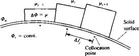
Подпись: дФ д( Ф, + p) 4l ~ dT ~ di Подпись: дЛ dl image449FIGURE 11.26

Doublet panels on the surface of a solid boundary.

equal to the internal potential plus the local potential jump /x across the solid surface:

Фи = Ф, + /і (11.74)

ЭФ*и

ai

Подпись: Q,= Подпись: (11.75)

The local external tangential velocity component above each collocation point can be calculated by differentiating the velocity potential along the tangential direction:

where / is a line along the surface. For example, the simplest numerical interpretation of this formula is

= —Д/— + 6,. (11.76)

where Alj is the distance between the two adjacent collocation points, as shown in the figure. This formulation is more accurate at the jth panel second corner point and can be used to calculate the velocity at this point. The pressure coefficient can be computed by using Eq. (11.18):

Подпись: 'Piimage450(11.77)

The contribution to the lift coefficient is then

AC,. = – Cp. Ц cos a, (11.78)

where A lj and ay are shown in Fig. 11.21. The total lift and moment are obtained by summing the contribution of each element:

L=2ALy (11.79)

/=1

N

Af0 = 2 АСДдсу cos a) (11.80)

,=і

and the nondimensional coefficients can be calculated by using Eqs. (11.12) and (11.13).

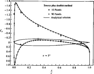
Example 1 Lifting thick airfoil. A short computer program (Program No. 8 in Appendix D) was prepared to demonstrate the above method and the same airfoil geometry was used as for the previous examples. Table 11.2 shows the

~иГ

-0.1795420

”0.8”

Иг

-0.1691454

0.7

Из

-0.1914112

0.01

И4

-0.2294960

-0.07

Из

Ив

=

-0.2296733 -7.9113595×10 2

RHS, =

-0.13

-0.12

Иг

9.1565706 х 10“2

-0.05

Ив

0.2577208

0.03

Ич

0.3524704

0.08

И ю

0.3651389

0.09

Combined Source and Doublet Method
numeric equivalent of Eq. (11.71) for N= 10 panels, along with the RHS vector and the solution vector (of the doublet strengths). These results are plotted in Fig. 11.27, which shows that even with such a low number of panels a fairly reasonable solution is obtained. When using a larger number of panels (N = 90) the solution is very close to the analytic solution at both the leading and trailing edges. As mentioned earlier, the potential-based influence computations (Eqs. (11.67) and (11.68)) and the pressure calculations (of Eq. (11.76) or Eq. (11.38)), seem to be computationally more efficient than the previous methods.

image451

FIGURE 11.27

Chordwise pressure distribution on a symmetric airfoil, using 10 and 90 panels (combined source/doublet method with Dirichlet boundary condition).

CONSTANT-POTENTIAL (DIR1CHLET BOUNDARY CONDITION) METHODS

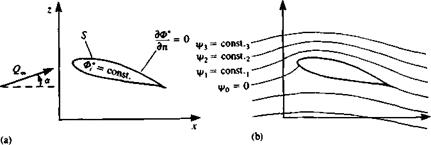
In the previous examples the direct, zero normal velocity (Neumann) boundary condition was used. In this section similar methods will be formulated based on the constant-potential method (Dirichlet boundary condition). This condition was described in detail in Section 9.2 and in principle it states that if дФ*/дп = 0 on the surface of a closed body then the internal potential Ф,* must stay constant (Fig. 11.25a)

Ф,* = const. (11.56)

It is possible to specify this boundary condition in terms of the stream function 4х (Fig. 11.256) and in this case the body shape is enclosed by the stagnation streamline where 4х = const, (which may be selected as zero). Many successful numerical methods are based on the stream function and they are very similar to the methods described in this chapter. Also, the stream function can describe flows that are rotational, but an equivalent three-dimensional formulation of such methods is nonexistent. Because of the lack of three – dimensional capability, only the velocity potential-based solutions will be discussed here.

Following Chapter 9, the velocity potential can be divided into a free-stream potential Ф* and perturbation potential Ф, and the zero normal velocity boundary condition on a solid surface (internal Dirichlet condition) is

Ф* = Ф + Ф* = const.

Placing the singularity distribution on the boundary S (and following the two-dimensional equivalent of Eq. (9.10)—see Eq. (3.17)) this internal boundary condition becomes

Ф*(х, z) = -^- f In (In/■)]*/£ + Ф„ = const. (11.57)

image446

FIGURE 11.25

Methods of fulfilling the zero normal velocity boundary condition on a solid surface.

and when the point (x, z) is on the surface then the coefficient 1/2л becomes 1 /л.

This formulation is not unique and the combination of source and doublet distributions must be fixed. For example, source-only or doublet-only solutions can be used with this internal boundary condition, but when using both types of singularity the strength of one must be prescribed. Also, any vortex distribution can be replaced by an equivalent doublet distribution, and therefore solutions based on vortices can be used too.

To construct a numerical solution the surface S is divided into N panels and the integration is performed for each panel such that

2 — I о In r dS — Ц —- (In r) dS + Ф„, = const.

i=l 2Л./panel j=1 2л /panel on

The integration is limited now to each individual panel element, and for constant, linear, and quadratic strength elements this was done in Chapter 10. For example, in the case of constant-strength singularity elements on each panel the influence of panel / at a point P is

image447(11.58)

in the case of a doublet distribution and for a source distribution

Подпись: -1 2л image448(11.59)

Once these influence integrals have been evaluated (as in Chapter 10) the boundary condition inside the surface (at any point) becomes

N N

X BjOj + X Cjfij + Фоо = const. for each collocation point (11.60)

y = l /=1

By a specification of this boundary condition on N collocation points, N linear equations can be created.

Constant-Strength Vortex Method

The constant-strength vortex distribution was shown to be equivalent to a linear-strength doublet distribution (Section 10.3.2) and therefore is expected to improve the solution of the flow over thick bodies. However, this method is more difficult to use successfully compared to the other methods presented here. One of the problems arises from the fact that the self-induced effect (Eq.

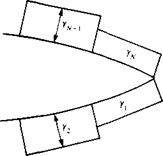
(10.43) ) of this panel is zero at the center of the element (and the influence coefficient matrix, without a pivoting scheme, will have a zero diagonal). Also, when using the Kutta condition at an airfoil’s trailing edge (Fig. 11.23) the requirement that Уі + Yn = 0 eliminates the lift of the two trailing edge panels. Consequently, if N panels are used, then only N — 2 independent equations can be used and the scheme cannot work without certain modifications to the method. One such modification is presented in Ref. 5.1 (pp. 281-282) where additional conditions are found by minimizing a certain error function. In this section, we try to use an approach similar to the previous source and doublet methods, and only the specifications of the boundary conditions will be modified. We will follow the basic six-step procedure of the previous sections.

Selection of singularity element. Consider the constant-strength vortex ele­ment of Section 10.2.3, where the panel is based on a flat surface element. To establish a normal-velocity boundary condition based method, only the induced velocity formulas are used (Eqs. (10.39) and (10.40)):

image443panel coordinates (11.44)

panel coordinates (11.45)

Подпись: FIGURE 11.23image444Constant-strength vorticity panels near the trailing edge of an airfoil.

Here, again, the velocity components (u, w)p are in the direction of the panel local coordinates, which need to be transformed back to the x-z system by Eq.

(11.23) .

This procedure can be included in an induced-velocity subroutine VOR2DC (where C stands for constant) that will compute the velocity (и, w) at an arbitrary point (x, z) due to the yth element:

(и, w) = VOR2DC (y,, z, Xjt zh xj+u z;+1) (11.46)

Discretization of geometry. In terms of generating the panel corner points (*;■ = 1. Zj=)> (*j=2, Zj=2), ■ ■ ■ , (xj=N+1, Zj=N+l), collocation points (jc, = 1, Z,=i). (*,=2. zi=2)> ■■■, (xi=N, z,=N), which are placed at the center of each panel, and the normal vectors n,-, the procedure of the previous section can be used (see Fig. 11.18).

Influence coefficients. A possible modification of the boundary condition that will eliminate the zero self-induced effect is to use an internal zero tangential- velocity boundary condition. This is based on Eq. (9.8), which states that inside an enclosed body Ф* = const. Consequently, the normal and tangential derivatives of the total potential inside the body are zero:

Подпись:<ЭФ* ЭФ* дп dl

In this particular case the inner tangential velocity condition will be used and at each panel:

(f/„ + u, + и>), • (cos or,, -sin or,) = 0 (11.47a)

In order to specify this condition at each of the collocation points (which are now at the center of the panel and slightly inside), the tangential velocity component is obtained by using Eq. (11.46). For example, the velocity at a collocation point 1, due to the yth vortex element is

(и, w)v = VOR2DC (Yj, xu zu Xj, zjt xj+l, zj+x) (11.48)

The influence coefficient at] is now defined as the velocity component tangent to the surface. Consequently, the contribution of a unit-strength singularity element j, at collocation point 1 is

а и = (и, w)v • (cos alt – sin or,)

where ax is the orientation of the panel (of the collocation point) as shown in Fig. 11.17. The general influence coefficient is then

йц = (и, w)ij • (cos ar„ – sin or,) (11.49)

By using this boundary condition the self-induced influence of the panel is
nonzero, and at the center of the panel, Eqs. (10.42) and (10.43) are recalled,

up(x, 0±) = ±| wp(x, 0±) = 0

Consequently, when і = j the influence coefficient becomes

al7 = – J (11.50)

Establish boundary condition (RHS). The free-stream tangential velocity component RHS, is found by

RHS, = —(£Л», Ж») • (cos <*,, -sin at) (11.51)

Note that in this case the free stream may have an angle of attack. The numerical procedure (using the double “DO loop” routine) for calculating the influence coefficients and the RHS, vector is the same as for the previous methods.

Solve Equations. Specifying the boundary condition for each (/ = 1 —* N) of the collocation points results in a set of algebraic equations with the unknowns y, 0 = 1 -* N). In addition the Kutta condition needs to be specified at the trailing edge:

Yi + У/v = 0 (11.52)

But now we have N + 1 equations with only N unknowns. Therefore, one of the equations must be deleted (e. g., the fcth equation) and by adding the Kutta condition the following matrix equation is obtained:

(

Подпись: RHS, RHS2Подпись:all ai2 ……………………..

a21 a22 ……………………………….

Подпись: IRHS^JJ 0 aN-1,1 aN-1,2 …………………..

t 1 0 0 • • ■

Caculation of pressures and loads. Once the strength of the vortices y, is known, the velocity at each collocation point can be calculated using Eq.

(11.48) and the pressure coefficient can be calculated by using Eq. (11.18) (note that the tangential perturbation velocity at each panel is y,/2):

Подпись:Подпись: (11.53)Cp = –

The aerodynamic loads can be calculated by adding the pressure coefficient or by using the Kutta-Joukowski theorem. Thus the lift of the )th panel is

AT, = pQ^Yj Де,

where Дcy is the panel length. The total lift and moment are obtained by adding the contribution of each element:

L = £aL, (11.54)

/=i

N

M0 = X cos or) (11.55)

/=i

and the nondimensional coefficients can be calculated by using Eqs. (11.12) and (11.13).

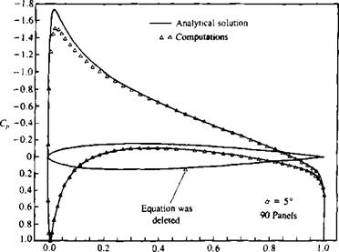
Example 1 Symmetric thick airfoil at angle of attack. The above method is applied to the symmetric airfoil of Section 6.6. The computed pressure distribu­tion is shown by the triangles in Fig. 11.24 and it agrees fairly well with the exact analytical results. The point where the computations disagree is where one equation was deleted. This can easily be corrected by a local smoothing procedure, but the purpose of this example is to highlight this problem. From the practical point of view it is better to use panels with a higher order (e. g., linear) vortex distribution or any of the following methods.

The sample student computer program that was used for this calculation is provided in Appendix D, Program No. 4.

image445

X

c

FIGURE 11.24

Chordwise pressure distribution on a symmetric airfoil at angle of attack of 5° using constant-strength vortex panels.