Category AERODYNAMICS

Constant-Strength Vortex Line Segment

Constant-Strength Vortex Line Segment Подпись: (10.114)

Early numerical solutions for lifting flows were based on vortex distribution solutions of the lifting surface equations (Section 4.5). The three-dimensional solution of such a problem is possible by using constant-strength vortex line segments, which can be used to model the wing or the wake. The velocity induced by such a vortex segment of circulation Г was developed in Sections 2.11-2.12 and Eq. (2.68b) states

If the vortex segment points from point 1 to point 2, as shown in Fig. 10.23,
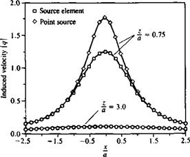
image391FIGURE 10.19

Comparison between the velocity induced by a rectangular source element and an equivalent point source along a horizontal survey line (median).

FIGURE 10.20
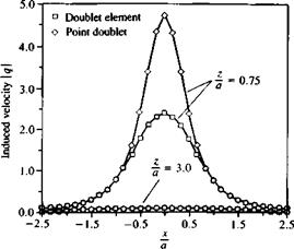
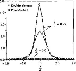
image392Comparison between the velocity in­duced by a rectangular doublet ele­ment and an equivalent point doublet along a horizontal survey line (median).

then the velocity at an arbitrary point P can be obtained by Eq. (2.72):

Подпись:„ – Г Г1 X r2 (t! Г2

1,2 4я|гіХг2|2Го rj r2)

For a numerical computation in a cartesian system where the (jc, y, z) values of the points 1,2, and P are given, the velocity can be calculated by the following steps:

1. Calculate X r2:

(Гі X r2), = (yp – y,)(zp – z2) – (zp – z,)(yp – y2)
(г, X r2)y = -(Xp – X)(zp – z2) – (zp – z,)(xp – x2)
(ri x r2), = (xp – х^ІУр – y2) – (yp – Уі)(хр – x2)
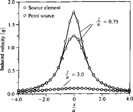
image393FIGURE 10.21

Comparison between the velocity in­duced by a rectangular source ele­ment and an equivalent point source along a horizontal survey line (diagonal).

FIGURE 10.22

Подпись: Induced velocity q image394Comparison between the velocity in­duced by a rectangular doublet ele­ment and an equivalent point doublet along a horizontal survey line (diagonal).

Also the absolute value of this vector product is

ki x r2|2 = (rt X r2)2 + (г, X r2)2 + (Гі X r2)2

2. Calculate the distances ru r2:

П = У/(хр – x,)2 + (yp – y,)2 + (z„ – zxf r2 = VC*p – X2)2 + (yp – y2f + (zp – Z2f

3. Check for singular conditions. (Since the vortex solution is singular when the point P lies on the vortex. Then a special treatment is needed in the vicinity of the vortex segment—which for numerical purposes is assumed to have a very small radius e)

IF (ru or r2, or Iг! X r2|2 < e)

where € is the vortex core size (which can be as small as the truncation error)
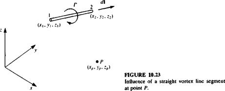
image395

THEN (M = v = w = 0)

or else u, v, w, can be estimated by assuming solid body rotation or any other (more elaborate) vortex core model (see Section 2.5.1 of Ref. 10.3).

4. Calculate the dot-product:

*b * r, = (X2 – x^iXp – Xi) + (y2 – уЖур – Ух) + (z2 – Z)(zp – Zi)

Го r2 = (x2 – Xi)(xp – x2) + (y2 ~ УїХУр – Уг) + (z2 – z^)(zp – z2)

5. The resulting velocity components are

и = X(rt x r2)x v = K(tt x i2)y w = K( rt x r2)2

where

image396

For computational purposes these steps can be included in a subroutine (e. g., VORTXL—vortex line) that will calculate the induced velocity (и, v, w) at a point P(x, y, z) as a function of the vortex line strength and its edge coordinates, such that

image397

As an example for programming this algorithm see subroutine VORTEX (VORTEX = VORTXL) in Program No. 12 in Appendix D.

Comparison of Near/Far-Field Formulas

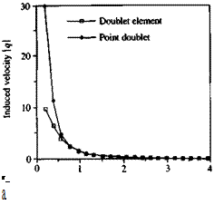
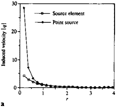
To demonstrate the possible range of applicability of the far-field approxima­tion, the induced velocity for a unit strength rectangular source or doublet element, shown in Fig. 10.16, is calculated and presented in Figs. 10.17-10.22 (figures based on Browne and Ashby102). The computed results for the velocity component parallel to r in Fig. 10.16 versus distance r/a (where a is the panel length as shown in Fig. 10.16) clearly indicate that the far-field and exact formulas converge at about r/a >2 (e. g. Figs. 10.17 or 10.18).

Similar computations for the total velocity induced by a doublet panel are presented in Fig. 10.18, and at r/a > 2 the two results seem to be identical.

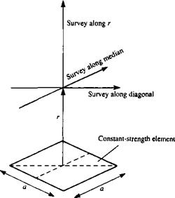
FIGURE 10.16

image388Survey lines for the velocity induced by a rectangular, flat element.
A velocity survey above the panel (as shown in Fig. 10.16) is presented in Figs. 10.19-10.22. Here the total velocity survey is done in a horizontal plane at an altitude of z/a =0.75 and 3.0, along lines parallel to the panel median and diagonal.

These diagrams clearly indicate that at a height of z/a = 0.75 the far-field formula (point element) is insufficient for both the doublet and source elements. However at a distance greater than z/a = 3 the difference is small and numerical efficiency justifies the use of the far-field formulas.

Подпись: a FIGURE 10.17

Comparison between the velocity induced by a rectangular source element and an equiv­alent point source versus height r/e.

FIGURE 10.18

Подпись: r_ a Comparison between the velocity induced by a rectangular doublet element and an equiv­alent point doublet versus height rja.

Constant Doublet Panel Equivalence to Vortex Ring

Consider the doublet panel of Section 10.4.2 with constant strength ц. Its potential (Eq. (10.104)) can be written as

fi f zdS 4л Js r3

Подпись: q = УФ = image385

where r = V(x – x„)2 + (y – y0)2 + z2. The velocity is

where we have used

JM = д_ _Э _____ Э__1

дхг3~ Эхо г3’ дуг3~ dy0r3

Now, let C represent the curve bounding the panel in Fig. 10.15 and consider a vortex filament of circulation Г along C. The velocity due to the

filament is obtained from the Biot-Savart law (Eq. (2.68)) as

Подпись:d X r

and for d = (dx0, dy0) and r = (x – x0, у – y0, z) we get

J

z z

■ і 3 <*Уо – j 1 d*o + k[(y – Уо) dxo-(x~ *0) dy0] с г r

Stokes theorem for the vector A is

VXA dS

and with n = к this becomes

Подпись: A • (Л =Подпись: 3AX 3y0 image386dS

Л f Г. 9 z Э z / Э x-x0 д у-уоЧ] An Js L* 9xn r3 1 dy0r3 9×0 r3 9y0 r3

Подпись: 4 Подпись: dS

Using Stokes’ theorem on the above velocity integral we get

Once the differentiation is performed, it is seen that the velocity of the filament is identical to the velocity of the doublet panel if Г = ц.

The above derivation is a simplified version of the derivation by Hess (in Appendix A, Ref. 12.4), which relates a general surface doublet distribution to a corresponding surface vortex distribution

Подпись: 4Подпись:image387f diX

J ^

■>c whose order is one less than the order of the doublet distribution plus a vortex ring whose strength is equal to the edge value of the doublet distribution.

Quadrilateral Doublet

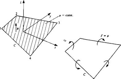
Consider the quadrilateral element shown in Fig. 10.15, with a constant doublet distribution. Using the doublet element which points in the z direction the velocity potential can be obtained by integrating the point elements:

Подпись:zdS

[(x-x0 )2 + (y-y0)2 + z2f/2

This integral for the potential is the same integral as the w velocity component

image384

FIGURE 10.15

Quadrilateral doublet element and its vortex ring equivalent.

of the quadrilateral source and consequently

Ф = – p – [tan" 4 ж L

tan-

^wi12e2 – h2^

+ tan-1

tan"1

(т2ъеъ – лз j

+ tan-1

ио_1(

(‘/П34Є4 – л4

( zr4 /

+ tan-1

tan_,

{m^ei-hiY

К zr! / J

(10.105)

(10.106)

The velocity components can be obtained by differentiating the velocity potential

ЗФ ЭФ ЭФ

Quadrilateral Doublet

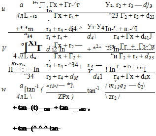
4л – [(x – *!)(* – x2) + (y – yO(y – y2) + z2]}

z(y2-y3)(r2 + r3)

hr2{rxr2 – [(x – XjKx – x2) + (y – y,)(y – y2) + z2]}

________________ z(x3-x2)(r2 + r3)__________________

r2r3{r2r3 – [(x – x2)(x – x3) + (y – y2)(y – y3) + z2]}

________________ z{xA – x3)(r3 + r4)________________

r3r4{r3r4 – [(x – x3)(x – x4) + (y – y3)(y – y4) + Z2]} ________________ z(x 1 – X4)(r4 + Г])__________________ 1

– [(* – – ^i) + (у – y4)(y – Уі) + z2]} J

[(^ – x2)(y – yQ – (x – xQ(y – y2)](rt + r2) ■гіГ2{ГГ2 – [(x – Xx)(x – x2) + (y – Ух)(у – y2) + z2]} [(x – x3)(y – y2) – (x – x2)(y – y3)](r2 + r3) r2r3{r2r3 – [(x – x2)(x – x3) + (y – y2)(y – Уз) + Z2}} [(x – x4)(y – Уз) – (x – x3)(y – y4)](r3 + r4) r3r4{r3r4 – [(x – x3)(x – x4) + (y – y3)(y – y4) + 22]}

[(JC – *i)(;y – ^4) -(.X – x4)(y – уО](л4 + rj) 1

and following Hess and Smith101 they are


z(yi ~ y2)(ri + r2)


и =


Quadrilateral Doublet

(10.107)


z{x2 – Xi)(ri + r2)


Quadrilateral Doublet

+


+


(10.108)


Quadrilateral Doublet

+


Quadrilateral Doublet

(10.109)


n [(x-x2)(y-y1)-(x-xl)(y-y2)](rl + r2)

ц; =:————————————————————————–

4л L – [(x – Xi)(x – x2) + (у – Уі)(у – y2)]}

| [(x – x3)(y – y2) – (x – x2)(y – y3)](r2 + r3)

r2r3{r2r3 – [(x – x2)(x – x3) + (y – y2)(y – Уз)]}

| [(x – x4)(y – Уз) – (x – x3)(y – y4)](r3 + r4)

r3r4{r3r4 – [(x – x3)(x – x4) + (y – y3)(y – y4)]}

1 [(-у-^хХу-у^-^-^Су-УїЖ^ + ‘-і) 1

r4r1{r4r1 – [(x – x4)(x – Xj) + (y – y4)(y – Уі)]} j

(Note that z = 0 must be used in the rk terms of Eq. (10.92), too.)


In Section 10.2.2 it was shown that a two-dimensional constant-strength doublet element is equivalent to two equal (and opposite direction) point vortices at the edge of the element. Similarly, in the next section we will show that the three-dimensional constant-strength doublet element is equivalent to a constant-strength vortex ring that is placed at the panel edges. Therefore, the above formulas for the velocity potential and its derivatives are valid for twisted panels as well (but in this case when the point P lies on the element the u, v velocity components may not be zero).

FAR FIELD. The far-field formulas for a quadrilateral doublet with area A can be obtained by using the results of Section 3.5 and are

Подпись: (10.110) (10.111) (10.112) (10.113) Ф(х, у, z) = z[(x – x0f + (y – y0f + z2]-3’2
_3M________ (x – x0)z________

“ 4* [{x-x0f + (y-y0)2 + z2r

ЗдА_______ (у-Уо)г________

4л [(x – x0)2 + (y – y0)2 + z2]512

M (x-x0)2 + (y-y0)2-2z2 4л [(x – x0)2 + (у – Уо)2 + z2]5f2

An algorithm for calculating the influence of this quadrilateral constant strength doublet panel is given in Appendix D, Program No. 11.

Quadrilateral Source

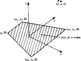
Consider a surface element with a constant-strength source distribution a per area bounded by four straight lines as described in Fig. 10.14. The element comer points are designated as (хг, yx, 0),… , (x4, y4, 0) and the potential at an arbitrary point P(x, y, z), due to this element is

<10s7)

and the velocity components can be obtained by differentiating the velocity potential:

Подпись:Подпись: ЭФ ЭФ ЭФ ~дх’~ду’ ~dz)image382"(10.88)

Quadrilateral Source

FIGURE 10.14

Quadrilateral constant-strength source element.


image383

Execution of the integration within the area bounded by the four straight lines requires a lengthy process, and the results are obtained by Hess and Smith.101 Using their results, the potential for a planar element becomes

ф – <T f Г (x ~ *і)(Уі – Уі) ~ (У ~ Уі)(*г ~ *і) іп г + гг + <*іг 4я 1L dl2 r, + r2-d,2

| (* – х2)(Уз ~ >2) -(У – Уі)(х з ~ х2) 1п г2 + г3 + d23

^23 Ь + г3- d23

, (* – х3)(у4 – Уз) -(у – Уз)(*4 – *з) 1п Гг + п 4- </34

г/34 Г3 + г4 – d34

, (* – *4)(Уі – >4) -(у – У*)(хі – *4) 1п г4 + Гі + d4 л

d41 r4 + r1-dAl

Quadrilateral Source

+ tan


du = V(*2 – *i)2 + (У2 – Уіf d-a = V(x3 ~ x2f + (л – Уг)2 dM = V(*4 – *з)2 + (У* ~ Уз)2 d*i = V(*i – x4f + (Уі – У*)2

Гк = л/(х – xk)2 + (у – yk)2 + z2 к = 1, 2, 3, 4 ek = (x – xkf + z2 к = 1, 2, 3, 4 hk = (x — xk)(y — yk) * = 1,2, 3,4 The velocity components, based on the results of Ref. 10.1, are

where


(10.90a)

(10.906)

(10.90c)

(10.90d)

(10.91a)

(10.916)

(10.91c)

(Ю.9Ы)

(10.92)

(10.93)

(10.94)


and


Quadrilateral Source

and


Quadrilateral Source

(10.95)


(10.96)


The и and v components of the velocity are defined everywhere, but at the edges of the quadrilateral they become infinite. In practice, usually the influence of the element on itself is sought, then near the centroid these velocity components approach zero. The jump in the normal velocity com­ponent as z—»0 inside the quadrilateral is similar to the results of Section 4.4.

w(z = 0±) = ±| (10.98)

When the point of interest P lies outside of the quadrilateral then

w(z = 0±) = 0 (10.99)

-oA

4W(* – x0)2 + (y – y0f +

Подпись: Ф(х, у, z) = Подпись: (10.100)

FAR FIELD. For improved computational efficiency, when the point of interest P is far from the center of the element (jc0, y0, 0) then the influence of the quadrilateral element with an area of A can be approximated by a point source. The term “far” is controlled by the programmer but usually if the distance is more than 3-5 average panel diameters then the simplified approximation is used. Following the formulation of Section 3.4 (in the panel frame of reference) the point source influence for the velocity potential is

The velocity components of this source element are

Подпись: (10.101) (10.102) Подпись:________ oA(x – x0)________

4л[(х – x0)2 + (y – y0)2 + z2fa

________ oA(y-y0)_________

________ oA(z – z0)________

4*[(*-x0)2 + (y-yo)2 + z2]3/2

Подпись: w(x, y, z) = Подпись: (10.103)

4n[{x – x0)2 + (y – y0)2 + z2]3a

A student algorithm for calculating the influence of a quadrilateral constant strength source element is given in Appendix D, Program No. 11.

THREE-DIMENSIONAL CONSTANT – STRENGTH SINGULARITY ELEMENTS

In the three-dimensional case, as in the two-dimensional case, the discretiza­tion process includes two parts: discretization of the geometry and of the singularity element distribution. If these elements are approximated by polynomials (both geometry and singularity strength) then a first-order approximation to the surface can be defined as a quadrilateral[2] panel, a second-order approximation will be based on parabolic curve-fitting, while a third-order approximation may use a third-order polynomial curve-fitting. Similarly, the strength of the singularity distribution can be approximated (discretized) by constant-strength (zero-order), linearly varying (first-order), or by parabolic (second-order) functions.

The simplest and most basic three-dimensional element will have a quadrilateral geometry and a constant-strength singularity. When the strength of this element (a constant) is unknown a panel code using N panels can be constructed to solve for these N constants. In the following section, such constant-strength elements will be described.

The derivation is again performed in a local frame of reference, and for a global coordinate system a coordinate transformation is required.

Quadratic Doublet Distribution

As indicated by Eq. (3.150) in Section 3.14 a quadratic doublet distribution is similar to the linear vortex distribution of the previous section. However, in situations when the Dirichlet type boundary condition is applied, it is more convenient to use the corresponding doublet distribution (instead of the linear vortex distribution). Thus, a quadratic doublet distribution along the x axis

Quadratic Doublet Distribution

image380

FIGURE 10.13

Quadratic-strength doublet element.


(jt, <x <x2) will have a strength distribution of

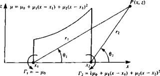
ИІx) = (*o + Pi(x ~ *i) + – Xyf

where the doublet elements pointing in the z direction [ц = (0, ju)] are selected, as shown in Fig. 10.13. Since the contribution of the constant and linear strength terms were evaluated in the previous sections, only the third term (ju(jc) = (i2x2) is considered and the influence at a point P(x, z) is an integral of the influences of the point elements between xx—*x2:

(10.77)

, 4 dl Г2 (x-x0)zxl J U{X>Z) Д,[(*-*„ )2 + z2]2dXo

(10.78)

, ч – Рг Г2 [(X – x0f ~ z2x% ^X’Z)~2nl Цх-х^ + г2]2

(10.79)

The integral for the velocity potential is obtained by introducing the variable X=x— x0 (thus dX = — dx0), which transforms Eq. (10.77) to the form

Подпись: dXГ~хг(x2-2xX + X2)z 2л X_Xl X2 + z2

The three integrals formed by the terms appearing in the numerator are evaluated in Gradshteyn and Ryzhik,6 3 pp. 68-69, and yield

ф(*> z) = ^ J(x2 – z2)(0! – в2) – xz ln^ + z(Jti – jc2)J

where the variables r,, r2, 6X, and 02 are shown in Fig. 10.13.

Note that Eq. (10.80) can be rewritten as

Подпись:Ф(*, 2) = Ф** + £-(х21Є1-х22в2)

such that Ф** is the potential of the equivalent linear vortex distribution of Eq. (10.71) (with ц2 = ~УіД).

Ф** = 2л [~XZ ІП% + “Xl) + _ z2^01 ” + 2л^202 “ *201^

(10.81a)

Therefore, Eq. (10.81) states that the potential of a quadratic doublet distribution is equivalent to the velocity potential of a linearly varying strength vortex distribution plus two concentrated vortices at the panel edges as shown schematically in Fig. 10.13.

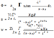
To obtain the velocity components we can use the similarity between Eq. (10.80) and the potential of a linearly varying strength vortex distribution (Eqs. (10.72) and (10.73)). Replacing ju2 with – ухІ2 in Eqs. (10.72) and

(10.73)

Quadratic Doublet Distribution Quadratic Doublet Distribution Подпись: (10.82)

and adding the velocity components of the two point vortices yields

Подпись: x X - x2 1 2 (x — x2)2 + z2 J (10.83
image381

and

The value of the potential on the element (z = 0±, Xj <x <x2) becomes

2

Ф(х. 0±) = ^(ві-в2)

and above the element вх — 62 = —л, whereas under the element вх — в2 = л. Consequently,

2

Ф(х, 0±) = T (10.84)

Similarly the velocity components become

Подпись: (10.85)u(x, 0±) = ^ (—2x)(02 – Єх) = T/x2x

86)

and the velocity is singular at the panel edges because of the point vortices there.

Note that for the general element, where ju(x) = ц0 + ju,(x – X]) + /і2(х – Xi)2, the potential jump at the edges of this doublet distribution results in two concentrated vortices. The vortex at xx will have a strength of —ц0 while the one at x2 will have a strength of [ju0 + Ц{х2 – Xj) + ju2(x2 – Xj)2], as shown schematically in Fig. 10.13.

Linear Vortex Distribution

In this case the strength of the vortex distribution varies linearly along the element

У(*) = Уо + Уі(*-*і)

Again, for simplicity consider only the linear portion where y(x) = ylx and y{ is a constant. The influence of this vortex distribution at a point P in the x-z plane is obtained by integrating the influences of the point elements between

Xi~>x2:

Подпись:(10.68)

(10.69)

Уі [xz, r z, N x2-x2-z2„ x2-x-z2

ф = — hr ln4 + o (*!-**)+———————— о——– ві————- о——-

Подпись: 2л 1 2 r2 2 Подпись: вг] (Ю.71)

Using the integral in Appendix В (Eq. (B.18)):

The velocity components are similar to the integrals of the linear source (Eqs. (10.51) and (10.52))

и = zln{*~X’l + Zl-2x(tan_1 ——————— tan’1 – Ml (10.72)

4 лі (x-x2) +z2 x-x2 x-xxJl

Подпись:■-—)]

X — Ху/J

(10.73)

When the point P lies on the element (z = 0±, x{<x <x2), then Eq. (10.71) reduces to

Подпись:Ф=±^(х2-х2)

4

At the center of the element this reduces to

Ф = ±¥±(х2ї + 2х1х2- 3×1)

Also, on the element

and at the center of the element (above +, under -):

W = ±^(*l+X2)

w = -%z(x1-x2)

Linear Doublet Distribution

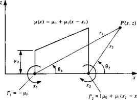
Consider a doublet distribution along the x axis with a strength ц(х) = fi0 + fi,(x — xx), consisting of elements pointing in the z direction [ц = (0, /х)], as shown in Fig. 10.12. In this case, too, only the linear term (ц(х) = цхх) is

image378FIGURE 10.12

Linearly varying strength doublet element.

considered and the influence at a point P(x, z) is an integral of the influences of the point elements between xl—*x2-

4 -/*1 Ґ2 *0*

Ф(ДС,2)“ 2л і, (*-*о)2 + *2 °

(10.56)

/ Ч /*1 Ґ2 *о(* – X0)z л__ и(Х’ } Я І, [(*-*o)2 + z2]2^0

(10.57)

/ ч -/*і Г2[(* -*о)2-*2К j W(X, Z) ~ 2Л і [(*-*0f + z22dXo

(10.58)

The integral for the velocity potential is similar to the w velocity component of the linear source (Eq. (10.46)). Therefore, following Eq. (10.49), the result is

ф*^[2,№-ад+2|п^]

(10.59)

and in cartesian coordinates

2*(tan 1———– tan 1——— )

x-x2 x—xx)

Linear Doublet Distribution

image379

Linear Doublet Distribution

To obtain the velocity components we observe the similarity between Eq.

(10.59) and the potential of a constant-strength vortex distribution (Eq. (10.37)). Replacing /2, with – y in Eq. (10.38) yields

ф’ ‘ [2<J: “ ‘■>,an ^ "2<jr “,г) ,an" ^+2

(10.38a)

and therefore the potential of the linear doublet distribution of Eq. (10.60) is

Ф = ф* *

+ ^(хів1-х2в2)


(10.61)


and the two last terms are potentials of point vortices with strengths [xlxl and (see Eq. (10.8)). The velocity components therefore are readily available, either by differentiation of this velocity potential or by using Eqs. (10.39) and

(10.9) :

Подпись:z z I

——– tan 1———

X—X2 JC-XjJ

Подпись: (10.62)/*1*2 г___________ /*1*1 г

2л (x – x2)2 -I – z2 2л (х – xt)2 + z2

and for the w component using Eqs. (10.40) and (10.10)

= _/*i (* *г)2 z2 /*i*i *~*i /*i*2 * *2

W 4л П (jc -*i)2 + z2 2л (j:-Xi)2 + z2 2л (x – x2)2 + z

The values of the potential and the velocity components on the element (z = 0±, Xi<x<x2) are

Ф = ^~rX 2

(10.64)

-r Ml

(10.65)

A*i Г. (x-x2)2 2×1 2×2 1 W 4jt L П(х – хг)2 x — Xi x — x2l

(10.66)

^1 f*2+*ll Jt lx2 — JCi J

and the w velocity component at the center of the element becomes

(10.66a)

and the velocity is singular at the panel edges because of the point vortices there.

Note that for the general element, where ц(х) = fi0 + Pi(x – *1), the potential becomes

ф=ф** “ ё ■(0z _ ві)+й(Xi ~Хг)вг (10-67)

and due to the potential jump at the edges of this doublet distribution two concentrated vortices exist. The vortex at xt will have a strength of -/r0 while the one at x2 will have a strength of [fii(x2 – x^ + ц0], as shown schematically in Fig. 10.12.

Linear Source Distribution

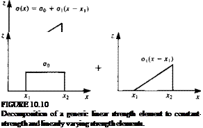
Consider a linear source distribution along the x axis (xl<x <x2) with a source strength of o(x) = ct0 + a,(x — xx), as shown in Fig. 10.10. Based on the principle of superposition, this can be divided into a constant-strength element and a linearly varying strength element with the strength o(x) = axx. Therefore, for the general case (as shown in the left-hand side of Fig. 10.10) the results of this section must be added to the results of the constant-strength source element.

image373

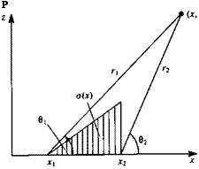
The influence of the simplified linear distribution source element, where o(x) = o1x, at a point P is obtained by integrating the influences of the point elements between xl-*x2 (see Fig. 10.11).

FIGURE 10.11

Подпись: P Nomenclature for calculating the influence of linearly varying strength source.

Linear Source Distribution

Details of the integration are presented in Appendix В (Eq. (B.13)), and the results are

(10.47)

where rlt r2, 0i, and 02 are defined by Eqs. (10.15) and (10.16). The velocity components are obtained by differentiating the velocity potential (Appendix B, Eqs. (B.14) and (B.15))

Подпись: (10.48) (10.49) m = ^ [Jln p + (*! – x2) + z(02 – 0X)

S [2 ln?,+:^-ад]

CTi Г* ~

Ф 4яІ 2

image376,image377

Substitution of rk, вк from Eqs. (10.15) and (10.16) results in

When the point P lies on the element (z = 0±, xi<x<x2), then Eq.

(10.50) reduces to

Ф = j1 [(*2 – *x) In (x – де,) – (x2 – xl) In [x – x2 – x(x2 – *1)] (10.53)

At the center of the element this reduces to

Подпись:-£<*М-г¥!-г)

Also, on the element

° Г, x – xi , Л, СГ,

W = ± — JC 2

and at the center of the element

CTi t

and

w = ±-(x2-xl)