As a first example for demonstrating the principle of numerical solutions, let’s consider the solution for the symmetric, thin airfoil. Because the airfoil is thin, no sources will be used, while the doublet distribution will be approximated by two constant-strength doublet elements (/r1( ju2, pointing in the – z direction). This element is equivalent to two concentrated vortices at the panel edges (see Fig. 9.16). However, the geometry of the “lumped-vortex” model was developed in Chapter 5, and by placing the vortex at the quarter chord and the collocation point at the three-quarter chord point of the panel the Kutta condition is automatically satisfied. Using this knowledge the equivalent discrete vortex model (with only two elements) for the airfoil is shown in Fig. 9.17. Also for the thin lifting surface only the Neumann (velocity) boundary condition can be used, because of the zero thickness of the airfoil. (Note that the doublet representation in Fig. 9.16 clearly indicates the existence of a
|
Г = Ml Г2 = И2 – Ml r„ = ^2

FIGURE 9.16
Constant-strength doublet element representation of the flat plate at an angle of attack (using two doublet panels pointing in the – z direction).
|
starting vortex at a large distance behind the airfoil which is shown in Fig. 9.17 too.)
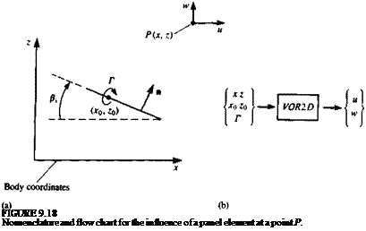
Selection of singularity element. For this very simple example the lumped – vortex element is selected and its influence is derived in terms of the geometry involved. Such an element is described in Fig. 9.18л, and it consists of a concentrated vortex at the panel quarter chord, a collocation point, and a normal vector n at the three-quarter chord. It is important to remember that this element is a simplification of the two-dimensional continuous solution and therefore accounts for the Kutta condition at the trailing edge of the airfoil.
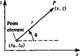
If the vortex of circulation Г of the element is at (jc0, Zo), then at an arbitrary point P(x, z), according to Section 3.8, the velocity induced by this element will be
Г (г-2b)
U 2л (x — x0)2 + (z — Zo)2 (лг-лср)
W 2л (x – x0f + (z – Zo)2
|
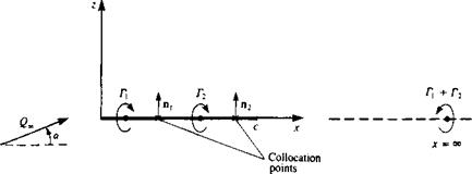
FIGURE 9.17
Equivalent discrete-vortex model for the flow over a flat plate at an angle of attack (using two elements).
|
and in a matrix form that is more useful for computations

where
This can be programmed as an influence coefficient subroutine in the manner shown in Fig. 9.186. Let us call this routine VOR2D and an algorithm based on Eq. (9.31) will have the form
(и, w) = VOR2D (Г, x, z, *o, Zq) (9.32)
Discretization of geometry and grid generation. For this example, the thin airfoil case is being solved (Fig. 9.17). For simplicity, only two elements will be used so that no computations are necessary. At this phase the geometrical information on the grid has to be derived. This can be automated by computer routines for more complex situations, but for this case the vortex point locations are
(•*oi. *o,) = (c/8, 0) (*o2, Z02) = (5c/8, 0)
and the collocation points are
(*ci, Zci) = (3c/8, 0) (*e2, zc2) = (7c/8, 0)
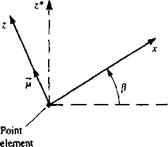
The normal vectors n must be evaluated at the collocation points, and for an arbitrary element і are
where the angle /3, is defined in Fig. 9.18a. In this particular case, when the airfoil has no camber and is placed on the z = 0 plane, both normals are identical:
ІІ! = (0, 1) n2 = (0,1)
Influence coefficients. Here the condition requiring zero velocity normal to the airfoil will be enforced. This boundary condition, according to Eq. (9.4), is
(q + Q«) • n = 0 (9.34)
The velocity q is induced by the unknown vortices, while the free-stream normal component can be calculated directly, and hence is moved to the right-hand side of the equation:
q • n = Q, • n (9.34a)
Because, in this case, the airfoil was divided into two elements with two unknown vortices of circulation Г1( T2, two equations based on the zero flow across the airfoil boundary condition will be derived at the collocation points. Defining as positive Г a clockwise rotation, the velocity induced by a unit strength vortex at point 1 on collocation point 1 is calculated with Eq. (9.32):
(«11, vt’n) = VOR2D (1.0, *cl, zcl, xm, z01) = (o, – ^ ^—j
and the velocity induced at collocation point 1, by a unit vortex at point 2, is
(«12, и’и) = VOR2D (1.0, xcl, zcl, x^, zm) = (o,
The velocity induced at collocation point 2, by a unit vortex at point 1 is
(«21, w2i) = VOR2D(1.0,xc2, zc2,x0l, Zoi) = (о, ~2д. .зс/4)
and the velocity induced at collocation point 2, by a unit vortex at point 2 is
(«22, *v22) = VOR2D (1.0, xc2, zc2, jc02, z02) = (o, – — *
The influence coefficients a,; are really the normal component of the flow velocity induced by a unit strength vortex element Г; at collocation point і:
a,/ = Ч, ДГ; = 1) • n, (9.35)
For the current problem, Eq. (9.35) is applied to collocation point 1 and to vortex point 1, thus
 -2
-2
Similarly for the second vortex,
0l2 = (Ml2, W’izXO, 1) = —
and for the second collocation point,
2
az = (M2i. И’гіХО» 1) = —
2
a22 = (U22> И>22)(0) 1) =
ЛС
Note that the left-hand side of Eq. (9.34a) can be described now as
q • n = 2 «оГ, for i = 1, 2 (9.36)
;=i
Establish RHS. The solution is based on enforcing the boundary condition of Eq. (9.34a) at the collocation points. Since the product Q„ • n is known it is transferred to the right-hand side of the equation:
q • n = – Q* • n = RHS (9.37)
It is useful to express the component of the free stream in vector form to allow easy vector operations; for this particular case the right-hand side (RHS) is
RHS, = -(l/., W.) • n, (9.38)
where (t/„, W„) = Q„(cos a, sin a). Computing the RHS vector for the two collocation points results in
RHSj = – gooSin a
RHS2= – Q„sin a
Solve linear set of equations. The results of the previous computations can be summarized as


 І a, jTi = RHS,
/=і
and explicitly, for this particular case,
/ —2/яс 2/яс /ГЛ -2/Зяс —2/яс/Г2/
which can be solved by standard matrix methods
Secondary computations: pressures, loads, velocities, etc. The solution of the

above set of algebraic equations is
The resulting pressures and loads can be computed by using the Kutta – Joukowski theorem (Section 3.11):
A U = pQSi
and by assuming a constant pressure distribution along the element, the pressure difference becomes
Ap, = pQSja
where a is the panel length. The lift and moment are then
2
L = 2 A A, = рОІ, лс sin a (9.40)
i=i
2 c2
M = — 2 A L/Х/ = – pj22jr—sin a (9.41)
i = l **
These results are similar to those for a zero-thickness symmetrical airfoil (Section 5.4) and equal to the exact flat plate solution (Section 6.5.1) and the method can easily be expanded to various camberline shapes and even multielement lifting airfoils.
Description of more complex methods for solving the potential flow problem will be presented in the following chapters.


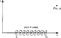 FIGURE 10.9

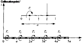


 (9.45)

