Category Aircraft Flight

Optimum economy with the jet engine

The fuel flow rate in a gas-turbine engine depends only on the throttle set­ting and is approximately proportional to the thrust produced by the engine rather than the power. Unlike the piston engine the efficiency of the turbo-jet engine (Chapter 6) improves with increasing dynamic pressure and reducing temperature. For optimum engine efficiency we therefore need to fly fast and high.

Because the engine efficiency increases with speed, the best speed to fly at is a compromise between the requirements of the airframe and the engine. Thus, unlike the piston engined aircraft, the best cruising speed will be somewhat higher than the minimum drag speed (Fig. 7.4).

Because of the way in which the engine behaves, we now need the dynamic pressure (and hence operating speed) to be as high as possible. Thus we need to design and operate the aircraft so that the best airframe performance is obtained at as high a speed as possible. The requirement for high speed is good news for the commercial operator, as we will see shortly. The aircraft should also be operated at high altitude so that the temperature of the air is low, to further improve engine performance.

As we have seen, reducing the wing area enables us to increase the dynamic pressure to compensate. In order to fly at high speed we therefore need an air­craft with the smallest possible wing area, consistent with acceptable low speed performance.

Flying high, too, has its limitations. The lower the air density the higher the stalling speed of the aircraft (Chapter 2). The maximum speed, for a conventional transonic airliner, will be dictated by the onset of problems associated with high Mach number (the buffet boundary Chapter 9), and so flight becomes possible over an increasingly restricted speed range as height is increased (Fig. 7.8). From an operational viewpoint a safety margin must be allowed to allow for accidental speed changes and for manoeuvres

Fig. 7.8 Effect of weight on stall and buffet boundary

A reduction in aircraft weight as fuel is used means that the intersection between stall and buffet boundaries occurs at a greater height

such as making turns which make extra demands on the wing lift as will be seen later.

Wing plan shape

The way in which the lift per metre of span varies along the span, depends on (among other things) the way in which the chord varies along the span. For untapered rectangular planform wings, most of the trailing vorticity is shed near the tips. In this case, the downwash will be greatest near the tips. If a tapered wing is used, the lift is increased at the centre, and trailing vorticity is produced more evenly along the span.

Theoretical analysis indicates that for a given amount of lift, the smallest amount of trailing vortex (induced) drag will be produced when the downwash is constant along the span. The same analysis also shows that the constant downwash condition is obtained if the lift per metre of span varies from zero at the tips, to a maximum at the centre, following an elliptical relationship, as indicated in Fig. 2.11. An elliptical spanwise variation of lift thus represents a theoretical ideal case for minimum trailing vortex drag.

On aircraft with unswept wings, an elliptical variation of lift can be produced by using a wing where the chord varies elliptically with distance along the span. Such wings have rarely been built, but one notable example

Wing plan shapeConstant downwash

Подпись: < Ml

Подпись: Lift at centre (maximum)

Lift/metre of span at distance у from centre = Lift at centre

Fig. 2.11 Elliptical variation of lift along the span

This variation gives a constant downwash along the span, and the minimum amount of trailing vortex (induced) drag shown in Fig. 2.12 is the Spitfire wing, which has a precise elliptical variation of chord.

There are manufacturing problems associated with an elliptical planform and furthermore, this shape is not ideal from a structural point of view. The structural designer would prefer the lift forces to be concentrated near the centre or root of the wing, so as to reduce bending moments. He would also like the depth of the wing spars to reduce towards the tips to maintain a con­stant level of bending stress. If the wing section shape were then to be the same at all positions, the chord would have to reduce accordingly. This would lead to the form of wing shown by the dashed lines of Fig. 2.13. The trailing vortex drag depends on the lift required, which in turn depends on the aircraft weight. A wing of this better structural shape should be lighter than the elliptical wing. The elliptical planform would only represent the shape for minimum induced drag if the weight of the wing structure were negligible. This is never the case, and by using a more efficient structural shape, it is possible to save weight. It therefore follows that for a real aircraft, the lowest drag would be given by a planform shape that was somewhere between the two extremes shown in Fig. 2.13; a compromise between the aerodynamic and structural ideals. In fact, a straight taper gives a good compromise, and has the advantage of being easy to construct. This factor shows the importance of integrating all aspects of aircraft design, and not trying to optimise any one feature in isolation.

The fact that an elliptical planform does not represent the true minimum drag shape for a practical aircraft was shown by Prandtl in 1933. It should be noted that the Spitfire was originally conceived with a simple tapered wing. The elliptical planform was adopted largely because of a need to increase the

Wing plan shape

Wing plan shape

Fig. 2.12 Elliptical and tapered planforms

The Spitfire (upper) had a wing with an elliptical variation of chord along the span. This theoretically gives the minimum amount of trailing vortex drag for a given wing area The Mustang (lower) used a wing with conventional taper, but improved aerofoil section. Merlin-engined versions of the two aircraft had similar performance, the Mustang being in some respects superior

The Spitfire shown in the photograph is actually a late Griffon-engined Mk-14

Wing plan shapePreferred planform for purely structural considerations

Elliptical planform for minimum trailing vortex (induced) drag

Fig. 2.13 Wing shapes for minimum trailing vortex (induced) drag and for structural efficiency. A straight taper gives a good compromise and is easier to manufacture The elliptical planform shown is that of the Spitfire section depth around mid-span to accommodate ammunition boxes and the undercarriage mechanism.

When engines are mounted on the wings, their weight reduces the bending stresses on the inboard sections of the wing. Little or no taper is thus required for the inboard sections. When an untapered centre section with tapered outer sections is used, the overall wing planform approximates roughly to the ellipt­ical aerodynamic ideal. Designers rarely seem to have taken advantage of this, but the DH Canada Dash-8 (Fig. 13.4) is one example.

On a straight-tapered or untapered wing, an elliptical distribution of lift may be produced by using a variation of incidence along the span; in other words, by twisting the wing. Spanwise variation of wing-section camber is also used in some designs.

For a given aircraft weight and flight altitude, the use of a fixed amount of twist or camber variation can only produce a truly elliptical lift distribution at one speed. This is not necessarily a major objection, however, as many other aspects of aircraft design are optimised for a preferred combination of speed, height and weight, or cruise condition.

Reducing frontal area

Strongly unfavourable pressure gradients can be avoided by making all parts of the aircraft as thin as possible: in other words, by reducing the frontal area. In the case of the fuselage of an airliner, any reduction in cross-sectional area must be offset by an increase in length, if the same number of passengers is to be accommodated to an equal standard of comfort. The increase in length is accompanied by an increase in the surface area, and this in turn means that the surface friction drag will increase. There is always an optimum comprom­ise between decreased boundary layer normal pressure (form) drag resulting from reduced frontal area, and increased surface friction drag caused by the increased surface area.

In the case of wing sections, reducing the thickness will result in a reduction in the depth of the structural spars. The bending strength of a spar depends on its breadth, and on the cube of its depth. Any small reduction in depth must be offset by a large increase in breadth, and hence weight. Thin wing sections also have the disadvantage that they stall at relatively low angles of attack. The reasons for the use of thin sections on transonic and supersonic aircraft will be described later.

Propellers

When the aircraft is in flight, the relative velocity between the air and a section of a propeller blade has two components, as illustrated in Fig. 6.4. The flight – direction or axial component comes from the forward flight velocity. The other (tangential) component comes from the blade velocity due to rotation.

If the propeller blade is set at a positive angle of attack relative to the resultant relative velocity, it will generate a force, in the same way as a wing generates lift. However, instead of resolving this force into lift and drag components, we may resolve it more conveniently into forward thrust, and tangential resistance. The resistance force produces a turning moment about the propeller shaft axis, and this is the resistance torque which the engine has to overcome.

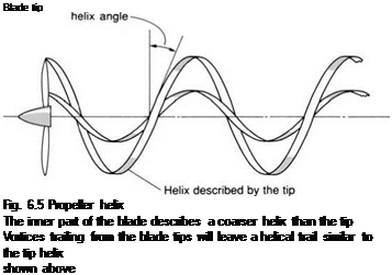
Any point on a blade describes a helix as it moves through the air, as shown in Fig. 6.5. The angle between the resultant velocity and the blade rotation direction is called the helix angle (see Figs 6.4 and 6.5). It will be seen that the

Propellers
Propellers
Подпись: Relative axial velocity
Подпись: Direction
Подпись: Thrust
Подпись: Helix angle

PropellersResultant relative

velocity

Fig. 6.4 Propeller geometry

Подпись: Blade tip Fig. 6.5 Propeller helix The inner part of the blade describes a coarser helix than the tip Vortices trailing from the blade tips will leave a helical trail similar to the tip helix shown above

The resultant aerodynamic force on the blade section can be resolved into thrust and resistance

inner part of the blade is describing a coarser helix than the tip. If all sections of the blade are to meet the resultant velocity at the same effective angle of attack, the blade will need to be twisted, so that the geometric pitch angle (defined in Fig. 6.4) is greater near the hub than at the tip. The blade twist can be seen in Fig. 6.6.

Propellers

Fig. 6.6 Advanced six-bladed high-aspect-ratio propellers on the Lockheed Super Hercules

The inner part of a propeller blade describes a coarser helix than the outer, so the blades are twisted along their length. The spinner covers the ineffective drag – producing centre, and also houses the pitch-varying mechanism. In this picture, the blades are feathered (turned edge-on to the wind) to prevent them from windmilling when the aircraft is parked. The turbo-prop engine, unlike the piston engine, has little resistance to turning when not in operation

The production of thrust by a propeller blade is similar to the generation of lift by a wing. It therefore follows that the blades will produce trailing vortices. Since the blades are rotating, however, the trailing vortices take the form of helical trails.

Engine installation

In many early multi-engined jet aircraft, the engines were buried in the wing roots, as in the British Comet airliner (Fig. 9.3), and Vulcan and Victor bombers. The pylon-mounted under-wing arrangement of the American Boeing 707 air­liner, and the B-47 bomber set a trend that has been followed to this day for large subsonic aircraft. The main advantage of the podded under-wing arrange­ment is that it reduces the wing bending moment, since the engine weight partly offsets the upward force due to wing lift. In addition, intake aerodynamic losses are lower in the shorter axi-symmetric pod arrangement, and access is better.

Tail or rear-fuselage mounting was once popular for all types of transport aircraft. This arrangement produces an aerodynamically cleaner wing, but the advantage is offset by the lack of wing bending-moment alleviation, and by problems arising from the engine intake being in the wake of the wing. For large aircraft, the under-wing arrangement is now preferred, but tail mounting is still popular for smaller transports such as the Hawker 800 businessjet illustrated in Fig. 10.22.

The complete aircraft

We have so far concentrated on the factors which make supersonic wings different from their transonic and subsonic counterparts and have seen some of the reasons which underlie the selection of a particular planform for a particular aircraft. Although a few aircraft, such as the Blackbird shown in Fig. 8.18, have been designed with integrated fuselage and wing geometry, by far the largest number of supersonic aircraft retain the traditional arrangement of a discrete fuselage joined to a wing.

When we were looking at the supersonic wing we were concerned mainly with the shock waves, and resulting wave drag, produced by the lifting surface. It was mentioned, albeit very briefly, that both the thickness and angle of attack

Fig. 8.17 Effect of planform on drag

Fig. 8.18 Configuration for Mach 3

The SR-71 used lifting fuselage chines as well as a highly swept delta wing (Photo courtesy of Lockheed California Co.)

of the wing would contribute to the wave drag. The ‘thickness’ contribution also applies to other components of the aircraft, particularly the fuselage. Since the primary object of the aircraft is to carry things, we are normally concerned to reduce wave drag as far as possible with respect to the volume of the aircraft; so wave drag is usually considered in two parts – the wave drag due to the volume and the wave drag due to lift. The volume wave drag is primarily affected by the cross-sectional area distribution.

Unconventional control surfaces

The use of multiple roll-control surfaces is advantageous, partly for reasons of safety, but also because conventional outboard ailerons may become just too effective at high speed, and can induce unacceptable wing bending and twisting moments. On many aircraft, including large airliners, a set of high speed ailerons may be fitted inboard of the usual low speed ones, as seen in Fig. 10.10. This reduces the amount of span available for installing flaps, how­ever, and one method of overcoming this problem, is to arrange at least one of these sets of control surfaces as so-called flaperons, where differential move­ment has the same effect as ailerons, and collective movement produces the effect of flaps. Flaperons are used on the F-16.

Fig. 10.15 Trailing-edge elevons on the delta-winged Concorde, shown drooped with power off

On delta-winged aircraft, trailing-edge elevons are fitted, as on Concorde (Fig. 10.15). Elevons are trailing-edge control surfaces which act as ailerons when operated differentially, and as elevators when operated collectively (i. e. both moving in the same direction).

One problem with delta-winged aircraft is that trailing-edge control surfaces cannot be used as flaps, without simultaneously behaving like elevators; pro­ducing a nose-down pitching moment, which has to be counteracted in some way. This is another reason why a canard foreplane is desirable on delta-winged aircraft. A combination of leading-edge flaps and elevons may also be used.

A final variant is the taileron used on the Tornado aircraft shown in Fig. 3.14. The slab tail surfaces can be operated differentially as ailerons, or collectively as elevators. Tailerons have a number of potential advantages. Like inboard high speed ailerons, they produce a smaller rolling moment than outboard wing mounted ailerons. They reduce the bending stresses on the wing, and allow more room on the wing for flaps. Notice the full-span flaps on the Tornado in Fig. 3.14.

When several sets of roll control surfaces are installed on one aircraft, the task of sorting out which surface to use in any particular condition is generally too much for the pilot to cope with, and the selection is normally made automatic­ally. In most cases, the pilot has some selection override capability. Davies (1971) gives a good account of roll control surface operation on typical airliners.

Longitudinal dynamic stability – pitching oscillations

Let us look first in greater detail at the motion we considered above in which we disturb the aircraft in pitch and then release it (Fig. 12.2). If the aircraft is

statically stable then the resulting pitching moment will be nose down, tending to return the aircraft to its original attitude. This restoring moment is very nearly directly proportional to the disturbance for a conventional aircraft operating at moderate Mach number. The way in which it is produced by the tailplane was described in Chapter 11. The resulting motion for a typical air­craft is shown in Fig. 12.2 and consists of a heavily damped oscillation in pitch, accompanied by very little change in height or speed. This motion has come to be called the ‘Short Period Pitching Oscillation’, or SPPO.

If the motion was solely caused by the restoring moment due to increased tail angle of attack, then the oscillation would continue with the same ampli­tude. It would then be said to be neutrally stable dynamically or ‘undamped’. During the motion, however, another effect is caused by the tailplane which is not apparent when we simply consider the ‘static’ forces due to the change in attitude.

Consider the instant in the motion when the aircraft is pitching, nose up, through its original attitude (Fig. 12.3). This pitching motion increases the angle of attack on the tail and hence produces a moment which opposes the nose-up pitching. Note that this effect depends on the rate of change of the attitude of the aircraft, or its angular speed. This speed is greatest at the time when the aircraft passes through the equilibrium position. It opposes the over­shoot (Fig. 12.3), thus tending to damp out the oscillatory motion. Because the oscillations eventually disappear the motion is dynamically as well as statically stable.

A further damping effect is provided because the angle of attack of the air­craft is increasing with time. The increase in the strength of the wing trailing vortex system, caused by the angle of attack increase, takes some time before it

Fig. 12.3 Damping of pitching oscillation

Angular velocity causes a lift force on tail which opposes the rotation in pitch and damps oscillation

makes itself felt at the tail. The tail lift is, therefore, a little greater than it would be if the angle of attack were held steady, and this again contributes to the damping effect.

The combined effect of these damping terms is usually very pronounced, and the motion is heavily damped, usually not lasting more than one or two cycles in a typical conventional aircraft configuration.

In the above paragraphs a very simplified view has been taken of the SPPO, since the emphasis has been on the major factors influencing the motion. In reality, as the angle of attack changes during the pitching motion of the aircraft, the lift will change, also in an oscillatory fashion. Thus the pitching motion will be combined with a vertical motion. A more detailed analysis of the motion shows that this has a slight influence on frequency but significantly increases damping.

Another, even more subtle, factor which we have ignored is the effect that the pitching motion has on the wing itself. This is explained by Fig. 12.4. As the wing rotates, the relative motion through the air produces a downwash over the front of the section and an upwash over the rear. This has the effect of changing the moment produced by the wing section, and this again will add slightly to the damping of the motion. If the wing is swept, this effect will be more pronounced because the distance between the root and tip sections will mean that an upwash will be produced at the tip and a downwash at the root.

>N

О

о

ф

ф

О)

О)

сг>

The air flow around an aerofoil section

In Fig. 1.13 we show the streamline patterns around an aerofoil section at a small angle of attack. Streamlines indicate the instantaneous direction of flow, and if the flow is steady, they also show the path that a particle would follow. Streamlines are defined as imaginary lines across which there is no flow. Therefore, the closeness of the lines gives an indication of flow speed. If the streamlines converge, the air is funnelled through at an increased speed, just as it does in the narrowing part of a duct, as described earlier (Fig. 1.10). Notice how the streamlines converge over the front of the upper surface of the aero­foil in Fig. 1.13, indicating an increase in speed, and diverge underneath, show­ing a decrease. A similar effect may be seen in the flow around the rotating cylinder in Fig. 1.12.

Some important features of the flow around the aerofoil may be seen by looking at the dividing streamline; the streamline which effectively marks the

The air flow around an aerofoil section

Fig. 1.13 Streamlines around an aerofoil

The dividing streamline meets the section just under the leading edge, at the stagnation position where the flow speed is momentarily zero, and the pressure reaches its maximum value

division between the air that goes over the wing, and that which flows under it. We have already mentioned that the flow divides not on the nose, but at a point under it, even on a flat plate. Notice also, how the air is drawn up towards the aerofoil at the front, as well as being deflected downwards from the trailing edge. This is also true for the spinning cylinder. Behind the wing of an aircraft, there is an overall downward flow of air, or downwash, but it should be noted, that this is predominantly a three-dimensional effect, as described in Chapter 2. The downwash seen in Fig. 1.12 would not be nearly so pronounced if the cylinder completely spanned the tunnel from wall to wall.

How the boundary layers form

In a laminar boundary layer, molecules from the slow-moving air near the surface mix and collide with those further out, tending to slow more of the flow. The slowing effect produced by the surface thus spreads outwards, and the region affected, the boundary layer, becomes progressively thicker along the direction of the flow. The way in which the boundary layers grow is illustrated in Fig. 3.2.

At the position called transition, an instability develops, and the flow in the layer becomes turbulent. In the turbulent boundary layer, eddies form that are relatively large compared to molecules, and the slowing down process involves a rapid mixing of fast and slow-moving masses of air. The turbulent eddies extend the influence outwards from the surface, so the boundary layer effectively be­comes thicker. Very close to the surface, there is a thin sub-layer of laminar flow.

Surface friction drag

Just as the surface slows the relative motion of the air, the air will try to drag the surface along with the flow. The whole process appears rather similar to the
friction between solid surfaces and is known as viscous friction. It is the pro­cess by which surface friction drag is produced.

The surface friction drag force depends on the rate at which the air adjacent to the surface is trying to slide relative to it. In the case of the laminar bound­ary layer, the relative air speed decreases steadily through the layer. In the tur­bulent layer, however, air from the outer edge of the layer is continually being mixed in with the slower-moving air, so that the average air speed close to the surface is relatively high. Thus, the turbulent layer produces the greater amount of drag for a given thickness of layer.