Category Airplane Stability and Control, Second Edition

Departures in Modern Fighters

In spite of the best efforts of designers to apply the departure research lessons of Moul, Paulson, Pinsker, Weissman, and others, fighter airplanes of the F-14, F-15, F-16, and F-18 generation have departure problems. The situation was summarized by the high angle of attack researcher and test pilots, NASA veterans Seth B. Anderson and Einar K. Enevoldson, and the young NASA Langley engineer, Luat T. Nguyen (1983). This is what they reported for specific airplanes:

Departures in Modern Fighters

Figure 9.12 System steady states plotted as a function of stabilizer angle for the Grumman F-14A Tomcat. The solid curves, for stabilizer angles more negative (trailing edge up) than —7 degrees, indicate stable trim conditions. Dashed curves for stabilizer angles between —5.4 and —6.7 degrees represent unstable trim points and those between two Hopf bifurcations are represented by the small dots. (From Jahnke and Culick, Jour of Aircraft, 1994)

Grumman F-14A Mild directional divergence and roll reversal start at an angle of attack of 15 degrees. Divergent wing rock and yaw excursions occur at an angle of attack of 28 degrees in the takeoff and landing configurations. A snap roll series can occur if the airplane is rolled at a high angle of attack. The pilot is located some 22 feet ahead of the airplane’s center of gravity. As a result, if yaw excursions are allowed to build up, cockpit lateral and longitudinal accelerations are high enough to interfere with the pilot’s ability to apply recovery control. A cure for F-14A departures was found by the NASA team, in a switch of roll control at high angles of attack from differential deflection of the horizontal tails to rudder deflection. This feature and foldout canards on the fuselage forebody are used on advanced, digitally controlled F-14As (Chambers, 2000).

General Dynamics F-16A and F-16B Yaw and roll departures are effectively prevented by a system that detects yaw rate above a threshold and automatically appliesspin recovery control: aileronswith and rudder against the yaw. However,

Departures in Modern Fighters

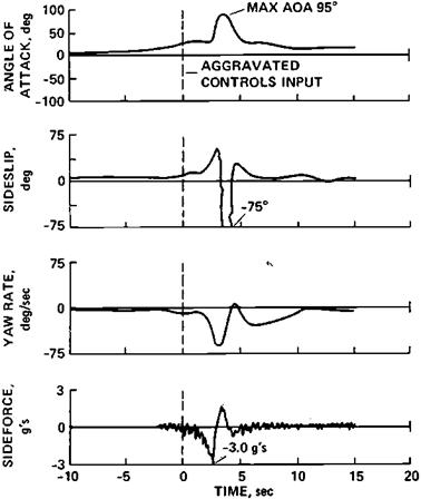
Figure 9.13 Transonic yaw departure obtained with a McDonnell Douglas F/A-18A by using pro­spin controls, or aileron against, and rudder with a turn at a medium angle of attack. (From Anderson, Enevoldson, and Nguyen, AGARD CP-347, 1983)

an angle of attack limiting system can be defeated in a number of ways, leading to excessive angles of attack.

McDonnell Douglas F/A-18A An automatic spin recovery mode, providing full control authority when yaw departure is sensed, can be defeated if the air­plane goes into a spin mode in which the yaw rate is relatively low. Although not a departure problem, the F/A-18A has an odd falling leaf spin mode, in­volving large sideslip, roll rate, and pitch rate oscillations. Response to pitch recovery control is slow. Finally, yaw departures are triggered by pro-spin con­trol applications at medium angles of attack and high subsonic Mach numbers (Figure 9.13).

Boeing F/A-18E/F An automatic spin detection and recovery mode has been added relative to older F/A-18 models. The falling-leaf characteristic of the F/A-18A/C is still present with the bare airframe. However, a new в feedback eliminates the falling-leaf mode (Heller et al., 2001).

Grumman EA-6B This airplane was not included in the AGARD survey paper by Anderson, Enevoldsen, and Nguyen. However, its nose-slice behavior at the stall is documented in AIAA Paper 87-2361 by Frank L. Jordan, David E. Hahne,

Matthew F. Masiello, and William Gato. Approaching the stall, the EA-6B first experiences a rolloff, followed by a nose slice. Numerous EA-6B accidents in fleet service attributed to departures led to a NASA research program on the problem (Chambers, 2000). An EA-6B fitted with NASA modifications (higher vertical tail, inboard wing leading-edge droop, etc.) had departure-free performance, but budgetary constraints prevented their application to service airplanes.

McDonnell Douglas F-15E Thisairplane islikewise not included in the AGARD survey. Its departure characteristics are described in Sitz, Nelson, and Carpenter (1997). Control laws are modified for yaw rates above 42 degrees per second, to increase differential tail power in recovery. Departures are found with lateral loading asymmetry. With the left wing loaded, at angles of attack above 30 degrees, rolls to the right are rapid and hard to counter.

Rockwell/MBB X-31 Departures of this research canard fighter at angles of attack of 60 degrees were corrected by a fuselage nose strake (Chambers, 2000).

The conclusion to be drawn from this survey is that departures can still be obtained on modern fighter airplanes. Designers should concentrate on understanding and controlling the vortex flows that often underlie departures, on simple warning cues and recovery procedures, and on crew restraint systems that permit functioning in the face of strong accelerations.

CHAPTER 10

The Lockheed S-3A Viking

Lockheed S-3A development followed a similar path to that for the McDonnell Douglas T-45A. That is, corrections for deficiencies found in the 1973 flight tests of the fourth S-3A airplane were stretched out over the next ten years. The original S-3A design had the same problem in carrier approaches as did the original T-45A Goshawk. With jet bypass engines delivering enough thrust at low engine rotation speeds to stay on the final approach path, “If all of a sudden you’re starting a settle coming into the carrier, you add power to regain altitude but nothing happens because of the delay in getting the engines to respond” (Wilson, 1992).

In the case of the S-3A, the belated fix was the direct lift control system described previously. Another belated stability and control fix to the S-3A for carrier suitability is thrust trim compensation. The S-3A’s low-slung engines produce longitudinal trim changes when power is used to adjust the final approach path angle, upsetting the desired constant angle of attack condition. The compensation moves the elevators automatically when the pilot adjusts the throttle position.

Canard Airplane Spin Recovery

Aerodynamic and mass criteria for good spin recovery of tail-last configurations are well known, as a result of years of experience and testing. A builder of a conventional tail-last configuration can rely on NASA spin recovery design charts with a fair degree of confidence. The NASA design charts specify minimum rudder and fuselage areas in certain locations, depending on calculated airplane moment of inertia parameters. The point is that airplane designers who cannot afford the expense of testing their designs in specialized spin-tunnel facilities or in model drop tests can still be reasonably assured of safe spin recoveries by using the NASA design charts and other guidelines.

The NASA spin recovery design charts do not specifically apply to canard configurations and can only offer the most general guide in those cases. A canard airplane designer should count on spin-tunnel or drop model tests, in order to ensure safe spin recoveries. Canard

Canard Airplane Spin Recovery

Figure 17.2 The canard six-place Jetcruzer, the first airplane to be granted a spin-resistant certification under FAA Part 23. Numerous attempts to spin the airplane were unsuccessful. (From AOPA Pilot, Aug. 1994)

surface tests by Neihouse in 1960 showed prospinning or propelling yawing moments for some canard sizes and locations on the fuselage nose.

Possible spin recovery problems are of course avoided if the airplane’s longitudinal control power is limited sufficiently so thatthe airplane cannot be stalled. An airplane’s main wing must be stalled and autorotation (Jones, 1934; McCormick, 1979) must be initiated before an airplane can spin. Even if the airplane stalls, spinning might still be avoided if rudder power is limited or coordinated with the ailerons, as in two-control airplanes such as the Ercoupe. Control limiting without penalty to the airplane’s utility is altogether feasible for modern computer-controlled fly-by-wire machines, such as the Northrop B-2 and Grumman X-29A.

For ordinary fly-by-cable airplanes, limiting longitudinal control power to that just needed to attain maximum lift coefficient can be defeated by loading the airplane to have a more aft center of gravity. Otherwise stated, limiting longitudinal control power to avoid stalling and spinning inevitably cuts down an airplane’s usable center-of-gravity range, reducing its util­ity. Some form of control limiting through center-of-gravity range has apparently been used in a recently certificated canard airplane. This is the six-place turboprop Jetcruzer, a prod­uct of Advanced Aerodynamics and Structures, Inc., of Burbank, California (Figure 17.2). Numerous attempts by test pilots to stall and spin the airplane were unsuccessful. The FAA granted the airplane a “spin-resistant”-type certificate, under the Federal Airworthiness Standards, Part 23.

Stabilizer Twist and Speed Stability

Collar and Grinsted (1942) showed that stabilizer setting can have an effect at high airspeeds on the variation with airspeed of the elevator stick forces required for trim. This variation is called speed stability. Push stick forces should be needed for trim at increasing airspeeds, so that if the stick is released, it will come aft, nosing the airplane up and reducing airspeed.

Airplanes with leading-edge-up rigged stabilizers will require trailing-edge-up elevator angles for trim in cruising flight. The up-elevator angles will put a down load on the stabilizer rear spar, tending to twist the stabilizer further in the leading-edge-up direction. Increasing airspeeds will increase the down load and twist, requiring increasing up-elevator angles and pull stick forces. This amounts to speed instability, pull forces needed for trim at increasing airspeeds rather than push forces. The Douglas A2D-1 Sky Shark, with an adjustable stabilizer, had this problem until its elevator tab was rigged trailing-edge up. This caused the elevator to float trailing-edge down in cruising flight and the stabilizer to be carried more leading-edge down, correcting the problem.

A reverse problem can occur on airplanes whose stabilizers are rigged leading-edge down. A leading-edge-down rig is used on some airplanes to improve nose-wheel liftoff for takeoffs at a forward center of gravity. A leading-edge-down rig can lead to excessive speed stability, requiring large push forces to trim in dives. If an airplane with a leading-edge-down stabilizer rig gets into an inadvertent spiral dive and push forces are not supplied, normal acceleration can exceed the structural limit. This effect is thought to be responsible for some in-flight structural failures, unfairly attributed to pilot inexperience in high-performance airplanes. W. H. Phillips considers this may be the cause for some failures of the Beech Bonanza (Phillips, 1998).

An aeroelastic problem related to stabilizer twist is spurious control inputs that result from airframe distortion under maneuvering loads. Fuselage deflection under positive load factor caused control inputs that increased load factor on the Vought F8U-1 airplane (Phillips, 1998). This was destabilizing in maneuvers. Reversing the position of a link in the elevator control system reversed the effect, providing stability instead.

Compensatory Operation and Model Categories

Pilot-in-the-loop analysis methods have had their earliest and most meaningful successes representing compensatory operation. As applied to pilot-in-the-loop operation, in compensatory operation or tracking the pilot operates on displayed or perceived errors to minimize them in a closed-loop fashion. Precognitive pilot operation is essentially open – loop; the pilot is not part of the tracking loop.

Mathematical models for pilot compensatory operation fall into two categories, struc­tural and algorithmic. Structural models reduce the pilot to subsystems such as muscle manipulators and vestibular sensors, each with transfer functions. Structural model pilot transfer functions contain delays, leads, and lags. The overall assemblage must reproduce pilot behavior in an end-to-end fashion. This challenging approach is made possible by careful frequency response measurements on human subjects (McRuer, 1973).

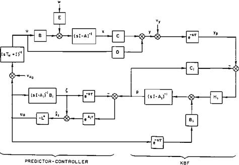
Pilot algorithmic models have grown out of modern optimal control theory. These models include an estimator, such as a Kalman filter, which processes the pilot’s observations to provide an estimate of the airplane’s state, and a controller, which is a mathematical model for the pilot’s regulation and muscular functions (Figure 21.2). Minimization or maximization of a criterion function provides the required results.

Compensatory Operation and Model Categories

Figure 21.2 Algorithmic pilot model, used in an optimal control loop. The airplane or plant matrices A, B, C, and D, including a noise-shaping filter E, are at the upper left. The airplane’s state is estimated by the Kalman-Bucy filter at the lower right. The optimal controller is on the lower left. (From Thompson, AIAA Paper 88-4183, 1988)

It is important to recognize that delay-lead-lag pilot models are needed primarily in analysis of compensatory operation of inner, generally attitude loops. Such loops are closed at high frequencies relative to pilot dynamics. Pure gain models for the pilot are generally adequate for analysis of turn coordination and lower frequency speed and path control loops.

The Future of Variable-Stability Airplanes

The engineers atNASA, Calspan, DERA, the Canadian NRC, Princeton University, and other European and Asian laboratories who had so much to do with the development of variable-stability airplanes can point to impressive accomplishments using these devices. Variable-stability airplanes shed light on many critical issues, such as the role of roll-to-yaw ratios on required Dutch roll damping, permissible levels of spiral divergence, and the effect of longitudinal flying qualities on instrument landing system (ILS) landing approaches. Variable-stability airplanes have also provided a preliminary look at the flying qualities of radical new airplanes such as the Convair B-58 Hustler; the Rockwell X-15, XB-70, B-1, and Space Shuttle Orbiter; the Lockheed A-12 and F-117A; the Grumman X-29A; various lifting body projects; and the Anglo-French Concorde before those new airplanes flew.

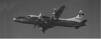
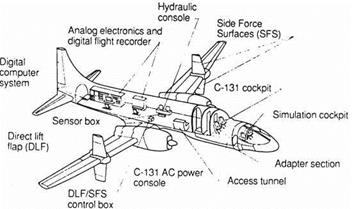
The TIFS machine, based on a reengined Convair C-131B transport, has had a particularly productive career (Figure 3.12). Calspan engineers provided the TIFS with the ability to add aerodynamic forces and moments to all 6 degrees of freedom. Flight tests are carried out from an evaluation cockpit built into the airplane’s nose, while a safety crew controls the airplane from the normal cockpit. Some 30 research programs have been run on this airplane. The majority of them were general flying qualities research; ten programs were on specific airplanes. A T-33 variable-stability airplane also had a very productive career, with more than 8,000 flying hours to date. A new application of variable-stability airplanes has been reported from the DLR, in which the ATTAS in-flight simulator investigated manual flight control laws for a future 110-seat Airbus transport airplane.

The Future of Variable-Stability Airplanes

The Future of Variable-Stability Airplanes

Figure 3.12 The TIFS (Total In-Flight Simulator) variable-stability airplane, built up by Calspan from a Convair C-131B airplane for the Air Force. The TIFS can generate direct lift and side force. (From Phillips, Jour, of Guidance, Control, and Dynamics, July-Aug. 1989)

In spite of this impressive record, there are reasons to look for limitations in the future use of variable-stability airplanes in the engineering development of new aircraft. A sig­nificant obstacle is the practical difficulty in updating and maintaining the vast computer data bases needed to represent the mathematical models of complex digital flight con­trol and display systems and nonlinear, multivariable aerodynamic data bases. Maintaining current data bases should be inherently easier for locally controlled ground-based simula­tors, as compared with variable-stability airplanes operated by another agency at a remote site.

Another limitation to the future use of variable-stability airplanes in the engineering development of specific airplanes has to do with the cockpit environment. Correctly detailed controls, displays, and window arrangements, important for a faithful stability and control simulation, may be difficult to provide on a general-purpose variable-stability airplane. Correct matching of accelerations felt by the pilot is also desirable. Although variable – stability airplanes do provide the pilot with both acceleration and visual cues, both cannot be represented exactly, along with airplane motions, unless the variable-stability machine flies at the same velocity as the airplane being simulated and unless the pilot is at the same distance from the airplane’s center of gravity in both cases.

Those conditions are rarely satisfied, except in some landing approach simulations. For example, the Princeton University VRA, flying at 105 knots, has been used to simulate the Space Shuttle Orbiter flying at a Mach number of 1.5. Pilot acceleration cues can be retained under a velocity mismatch of this kind by a transformation of variable-stability airplane outputs that amounts to using a much higher yaw rate (Stengel, 1979). Likewise, pilot location mismatch is conveniently corrected for by a transformation on the sideslip angle. If these transformations are applied to correct pilot acceleration cues, visual cues will be made incorrect. An alternative scheme to provide correct pilot acceleration cues relies on the direct side and normal force capabilities of advanced machines such as the TIFS.

In general, the cockpit environment of a new airplane can be represented fairly readily in a ground-based simulator. Correct visual cues can be provided as well, although there are often troubling lags in projection systems. The major loss in fidelity for ground simulators, as compared with variable-stability airplanes, comes from the compromises or actual losses in pilot motion cues. When these are provided by servo-driven cabs, accelerations must be washed out. That is, to avoid unreasonably large simulator cockpit cab motions, only acceleration onsets can be represented. Sustained accelerations must be tapered off smoothly and quickly in the ground-based systems, or they must be simulated by pressures applied to the pilot’s bodies with servo-controlled pressure suits. Belsley (1963) provided an early summary paper in this area. Later on, Ashkenas (1985) and Barnes (1988) reviewed the utility and fidelity of ground-based simulators in flying qualities work.

There is a debatable size problem involved with the use of variable-stability airplanes. W. H. Phillips points out that in Robert Gilruth’s original handling qualities studies, contrary to the expectationsof many people, pilotswere satisfied with much lower valuesof maximum rolling velocity on large airplanes than on small ones. This finding is reflected in the pb/2V criterion of acceptability, which allows half as much maximum rolling velocity when the wing span is doubled at the same airspeed.

Again, pilots of small airplanes choose lower control forces than do pilots of large air­planes. Phillips concludes that pilots adapt to airplanes of different sizes and that erroneous results may be obtained if this adaptable characteristic of the human pilot is not accounted for. This might be the case when a large airplane is simulated with a much smaller variable – stability airplane, or vice versa.

A counterargument is that two fundamental airplane dynamics properties affecting air­plane feel vary systematically with airplane size, giving the pilot a cue to the size of the airplane, even if all that the pilot sees of the airplane is the cockpit and the forward view out of the windshield. Short-period pitch natural frequency shows a systematic trend downward with increasing airplane weight and size. The roll time constant, the time required for an airplane to attain final rolling velocity after step aileron inputs, shows a systematic trend upward with increasing airplane size.

Thus, a small variable-stability airplane whose dynamics match those of a large airplane may well feel like the large one to the pilot. W. O. Breuhaus (1991) reports that this seems to be the case:

the pilot must be able to convince himself that he is flying the assigned mission in the airplane being simulated… one of the variable-stability B-26’s was used to simulate the roll characteristics of the much larger C-5A before the latter airplane was built. The results of those tests showed a less stringent roll requirement for the C-5A than was being specified for the airplane, and these results were verified when the C-5A flew.

The relative meritsof variable-stability airplanesascompared with ground-based simula­tors for representing airplane flying qualities are still being debated; each has its proponents. However, it is a fact that sophisticated ground-based simulators are now absolutely inte­gral to the development of new aircraft types, such as the Northrop B-2 and the Boeing 777. Typically, ground-based simulators handy to the engineering staff are in constant use during airplane design development. At the same time, variable-stability airplanes remain important tools for design validation and for the development of generalized flying qualities requirements.

The question of when variable-stability airplane simulation is really necessary is taken up by Gawron and Reynolds (1995). They provide a table of ten flight conditions that seem to require in-flight simulation, together with evidence for each condition. An example condition is a high gain task. Evidence for this is the space shuttle approach and landing and other instances such as YF-16 and YF-17 landings.

The Air Force operates the new VISTA/F-16D variable-stability airplane (Figure 3.13) and the Europeans are running impressive programs of their own. However, in-flight simulation was not considered for the Jaguar fly-by-wire, the EAP (Experimental Aircraft Programme), or for the Eurofighter. Shafer (1993) provides a history of variable-stability airplane operations at the NASA Dryden Flight Research Center, with an extensive bibliography.

Springy Tabs and Downsprings

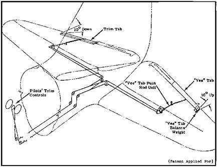
Sometimes called “Vee” tabs, springy tabs first appeared on the Curtiss C-46 Commando twin-engine transport airplane. Their inventor, Roland J. White, used the springy tab to increase the C-46’s allowable aft center of gravity travel. White was a Cal Tech classmate of another noted stability and control figure, the late L. Eugene Root. Springy tabs increase in a stable direction the variation of stick force with airspeed. A springy tab moves in one direction, with the trailing edge upward. It is freely hinged and is pushed from neutral in the trailing-edge-upward direction by a compression spring (Figure 5.15). An NACA application mounted the springy tab on flexure pivots.

The springy tab principle of operation is that large upward tab angles are obtained at low airspeeds, where the aerodynamic moment of the tab about its own hinge line is low compared with the force of the compression spring. Upward tab angle creates trailing-edge – down elevator hinge moment, which must be resisted by the pilot with a pull force. Pull force at low airspeed is required for stick-free stability.

The C-46 springy tabs were called Vee tabs because the no-load-up deflection was balanced aerodynamically by the same down rig angle on a trim tab on the opposite elevator (Figure 5.15). The C-46 springy tabs were also geared in the conventional sense. The compression spring that operated the C-46’s springy tab was a low-rate or long-travel spring with a considerable preload of 52 pounds. Tab deflection occurred only after the preload was exceeded, making the system somewhat nonlinear.

Springy Tabs and Downsprings

Figure 5.15 Schematic diagram of the elevator trim and vee-tab installations on the Curtiss C-46 Commando. The vee tab augments static longitudinal stick-free stability. (From Rumph and White, Curtiss Rept. 20-Y48, 1945)

Springy tabs were also used successfully on the Lockheed Electra turboprop. Although White is considered the springy tab’s inventor and was the applicant for a patent on the device, it may have been invented independently by the late C. Desmond Pengelly. Springy tabs are not in common use currently because of potential flutter. Irreversible tab drives are preferred to freely hinged tabs from a flutter standpoint.

A flutter-conservative means of accomplishing the same effect as a springy tab is the downspring. This is a long-travel spring connected between the elevator linkage and air­plane fixed structure. The stick or yoke is pulled forward by the long-travel spring with an essentially constant force. Elevator aerodynamic hinge moment, which would normally fair the elevator to the stabilizer, is low compared with the spring force, and the pilot is obliged to use pull force to hold the elevator at the angle required for trim. As with the springy tab, this provides artificial stick-free stability. Downsprings are often found in light airplanes. If the yoke rests against its forward stop with the airplane parked, and a pull force is needed to neutralize yoke travel, either a downspring is installed or, less likely, the elevator has mass unbalance.

Simplifications and Explications

It is not surprising that the mathematical complexity of the inertial coupling prob­lem and the relatively crude state of early analog and digital computers led researchers and designers to try to capture the essence of the problem with simplified mathematical models. With current computer technology, most engineering groups faced with such a problem would probably run the problem without simplification, but automate it so as to use a minimum amount of engineering time.

A strategy made possible by modern digital computers would be to step through au­tomatically all combinations of rolling velocity, Mach number, altitude, center of gravity, initial load factor, stability augmentation feedback, and control usage. This would generate vast numbers of 5- or 6-degree-of-freedom transients. While still in computer memory, the transients could be screened by algorithms that look for excessive air loads or divergences. Only the interesting cases would be retrieved for engineering examination.

Simplifications and Explications

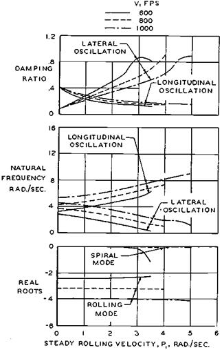
Figure 8.6 Effect of steady rolling on small-perturbation modes of motion of the Douglas F4D-1. Damping of the longitudinal short-period oscillation is halved at high roll rates. (From Abzug, Jour. of the Aero. Sciences, Nov. 1954)

However, back in the late 1940sand 1950s, ingenioussimplificationswere the order of the day rather than the modern head-on approach hypothesized above. Leading the simplification parade in the early days was W. H. Phillips’ original work, in which he squeezed the inertial coupling problem down to the solution of a simple quadratic equation. Six of the engineers who came shortly afterward tried to improve on the simplified Phillips model.

An early approach linearized the full 6-degree-of-freedom equations of motion under conditions of steady rolling (Abzug, 1954). Calculations for the F4D Skyray showed a re­duction in damping and increase in frequency of the longitudinal oscillation as roll rate increased beyond about 150 degrees per second (Figure 8.6). The succeeding simplified approaches are documented in the proceedings of the Wright Field Inertial Coupling Con­ference (Westbrook, 1956).

Robert Bratt and Charles DaRos reduced the inertial coupling problem to the solution of a quartic, whose roots they determined as functions of rolling velocity. This required setting lateral acceleration to zero and rolling velocity and normal acceleration to constants. Very interesting by-products of the Bratt-DaRos approach were steady-state solutions for angles of sideslip and attack under rolling conditions.

Cecil Carter returned to the Phillips model, but added two additional degrees of freedom, translation along the lateral (Y) and normal (Z) axes. Carter found stability boundaries from the resultant fourth-degree characteristic equation by Routh’s criterion, a fairly standard procedure. Unfortunately, in checking the stability boundary results against 20 actual roll time histories, only fair agreement was found, and Carter concluded that the modified Phillips method needed to be supplemented by more exact calculations.

Like Bratt and DaRos, Schmidt, Bergrun, and Merrick reasoned that the steady-state angles of attack and sideslip reached in steady roll would be useful indices of the sever­ity of any unwanted excursions. Their method, partly based on a more limited study by Uddenberg at Boeing, used the full 5-degree-of-freedom (airspeed constant) equations of motion with only very minor simplifications. Very interesting correlations appeared with not only Phillips’ work, but also with complete simulations and a flight test point for the North American F-100A. The Schmidt, Bergrun, and Merrick analysis predicted quite accurately the gains obtained with a larger vertical tail on the F-100A.

Kelley at Grumman started with the Abzug equations for steady rolling, eliminating the cyclic gravity terms and other small terms and implicitly incorporating F-11F stability derivatives. A preliminary linear algebraic solution, including some trial and error because of the dependence of stability derivatives on the answers, found steady-state values of pitching velocity and angles of attack and sideslip corresponding to some steady rolling velocity. A final perturbation solution from the steady-state values was found from fifth-order linear differential equations. Kelley limited this to just the roots, determining stability.

The sixth post-Phillips venture in inertial coupling simplification was that by Gautraud and Flanders at MIT. They too linearized the problem around a presumed steady rolling condition, but adopted a more controls-oriented approach, finding both poles and zeros for the Convair F-102.

Augmenting the inertial coupling simplification studies was the work done to explain the phenomenon and to pick it apart for specific cases. What factors are really important? John Wykes dissected the F-100 yawing and sideslip acceleration time histories, showing the relative importance of aerodynamic, engine gyroscopic, and inertial terms as the roll proceeded (Figure 8.7)

Engine angular momentum enters into the inertial coupling problem as a bias in one direction of roll. Divergence occurs at a slightly lower roll rate when rolling in a sense opposite to engine rotation (Pinsker, 1957). Propeller and engine gyroscopic effects occur as well in other flight regimes, especially when aerodynamic forces and moments are relatively low, such as in spins and in takeoff.

High Mach Number Difficulties

As airplanes approach and exceed the speed of sound, 761 miles per hour at sea level, the air’s compressibility changes the nature of the flow. The Mach number, the ratio of airspeed to the speed of sound, is how we keep track of these flow changes and their effects on airplane stability and control. First encountered in flight in the early 1940s, compressibility effects are still a consideration for designers of high-speed airplanes.

5.1 A Slow Buildup

Our understanding of the compressibility effects on airplane stability and control grew slowly by a buildup of theory and wind-tunnel data, with no counterpart in flight test experience for many years. The buildup in the theory started as far back as 1916, with work by Lord Rayleigh, followed by G. H. Bryan in 1918. Wind-tunnel studies started, too, but it was not for more than 20 years, or in the early years of World War II, that compressibility suddenly appeared as a stability and control problem in flight.

A key early theoretical result came from the ubiquitous Hermann Glauert, around 1927. This was the Prandtl-Glauert rule, applying to the variation of pressure coefficient with Mach number. The rule gives the pressure coefficient at any Mach number as the incompressible value, increased by a simple function of the Mach number. The Prandtl-Glauert rule was developed by the theory of small perturbations. A similar rule was developed around 1941 by Theodore Von Karman and H. S. Tsien. Their formulation is called the Karman-Tsien rule.

Early high-speed wind-tunnel tests were made in very small wind tunnels, compared with the larger sizes available for low-speed testing. Drs. Hugh L. Dryden and Lyman J. Briggs tested airfoils in a small supersonic jet in the 1920s. At NACA’s Langley Laboratory in the early 1930s, John Stack built small high Mach number wind tunnels as adjuncts to an existing pressurized low-speed wind tunnel. High-pressure air from the big tunnel was vented into a small vertical wind tunnel, downstream from the vertical tunnel’s test section.

At first, Stack and his group limited their tests to airfoils used in propellers, since at that time only propeller tips had experienced compressibility effects. By the end of the 1930s the work had broadened to include other airfoils. Pressure distributions showed a distinct upper surface discontinuity or jump, which Stack called the compressibility burble (Figure 11.1). Burble occurs at a critical airspeed at which the local surface velocity reaches the speed of sound. The local surface velocity at any point on an airfoil is the sum of the airspeed and the velocity induced by the airfoil shape. Stack reasoned that increases in the critical airspeed or Mach number could be attained through the development of airfoils that had minimum induced velocity for any given lift coefficient and thickness. This insight was the genesis of the first airfoils designed specifically for high Mach number flight.

Vee – or Butterfly Tails

A vee-tail or butterfly tail is a wing with a large amount of positive dihedral. If the vee-tail is built with negative dihedral, or anhedral, it is called an inverted vee-tail. Vee-tails or inverted vee-tails are used instead of the usual horizontal and vertical tails, replacing three surfaces with two. The Beech Model 35 Bonanza is the vee-tailed airplane most people have seen. Over 12,000 of them have been built. A very early vee-tail installation was made by Rudlicki in 1931 (Figure 14.10).

Why vee-tails? An evident advantage is that there is one fewer tail surface to build, assuming that horizontal tails are built in two halves. There is also less interference drag because there is one fewer tail-fuselage junction. Other possible advantages are dependent on the configuration. The inverted vee-tail of the General Atomics Gnat 750 protects the pusher propeller, serving as a bumper for tail-down landings (Figure 14.11).

Entire vee-tail surfaces, or flaps on their trailing edges, are deflected symmetrically for pitch control and asymmetrically, that is, with equal and opposite angles, for yaw control. There is a small rolling moment generated in the asymmetric case. For vee-tails with positive dihedral the rolling moment is adverse, in the following sense. Right rudder and yawing moment are generally applied by a pilot or autopilot during right rolls, to overcome adverse yaw. However, with a positive dihedral vee-tail, a left rolling moment is generated by the

Vee - or Butterfly Tails

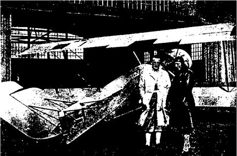
Figure 14.10 Polish engineer Georges Rudlicki (on the left) with test pilot W. Szubczewski in front of the Hanriot 14 biplane fitted with Rudlicki’s V-tail design in 1932. This configuration was successfully tested by Szubczewski and two other pilots. (From Aircraft Engineering, March 1932)

Vee - or Butterfly Tails

Figure 14.11 An inverted vee-tail airplane, the Amber, predecessor of the General Atomics Gnat 750 UAV (Unmanned Aerial Vehicle), used in 1994 forU. S. reconnaissance over Bosnia. (From Leading Systems, Inc.)

right rudder deflection, opposing the ailerons. Of course, this effect is reversed for inverted vee-tails, favorable rolling moments accompanying rudder deflection in rolls.

Negative tail dihedral plays an important role in avoiding pitchup for swept-wing air­planes at high subsonic Mach numbers. Though strictly not inverted vee-tails, negative tail dihedral is found on such airplanes as the McDonnell Douglas F-4 Phantom and the Dassault/Breguet/Dornier Alpha Jet.

Vee-tail surface stalling has been a continuing stability and control concern. A dangerous, abrupt pitch-down due to tail stall during landing approaches is possible. This could happen at forward center of gravity positions, with landing flaps full down, requiring down tail load for trim. If at the same time the landing approach is being made in rough air, appreciable sideslip angles can develop while the pilot fights the Dutch roll mode of motion. The combination of large down load and sideslip excursions could bring momentarily one vee – tail panel beyond its stall, relieving part of the down load and causing an abrupt diving moment.

Professor Ronald O. Stearman has looked into vee-tail stalling in sideslips at forward centers of gravity as a possible cause of the relatively high accident rate of the vee-tailed Beech Model 35. The Model 35’s accident rate is seven times as high as the Beech Model

33, which is essentially the same airplane equipped with a conventional tail. Stearman’s (1986) tests show that a vee-tail panel would stall, causing the Model 35 to nose over at a sideslip angle of 10 to 12 degrees. Flight tests conducted for Beech failed to reproduce Stearman’s results. Vee-tail stalling remains a potential problem, which is an argument for making vee-tails somewhat oversized. Oversized tail surfaces would decrease the panel angles of attack required to produce given tail loads.

Estimation of required vee-tail size and dihedral angles was dealt with definitively by Paul E. Purser and John P. Campbell (1945). A naive approach to the problem would merely take the vee-tail’s projected areas in plan and side views as effective horizontal and vertical areas, respectively. However, the Purser-Campbell method deals with the actual panel loads, considers interference between the vee-tail panels, and works out the trigonometry for panel angle of attack and force resolution. Purser and Campbell provide convincing experimental verification of their vee-tail theory, using wind-tunnel test data (Figure 14.12).