Category Airplane Stability and Control, Second Edition

The Rotation-Only Breakthrough

The rotation-only concept for variable sweep was pioneered by Dr. Barnes Wallis at Vickers-Armstrongs, Weybridge, around 1954. Starting in 1959, brilliant work by a NASA Langley Laboratory team, including Dr. Wallis, made variably swept wings a practical design option. Team members William J. Alford, Jr., Edward C. Polhamus, and Wallis found a practical way to eliminate the translation, or fore-and-aft motion of the wing inboard ends, drastically simplifying the variable-sweep rotation/translation mechanism to rotation alone.

The clue was to pivot the wings well out from the airplane centerline and to bring the wing trailing edges when fully swept parallel and close to the horizontal tail leading edges. In the Alford-Polhamus-Wallis design, the wing pivots are on the outboard ends of a glove, a diamond-shaped, highly swept inboard fixed-wing section. Wing spanwise loads are carried primarily on the outboard or unswept panels when the wings are in the forward position. The wing’s spanwise load shifts relatively inboard, to the glove, when the wings are in the aft position. This relative load shift is exactly what one wants in order to minimize movement of the total wing aerodynamic center when the wings go through its sweeping routine (Loftin, 1985). Alford and Polhamus jointly hold the U. S. patent on this design.

An additional benefit of the Alford-Polhamus-Wallis arrangement arises from downwash changes with wing sweep. Bringing the wing trailing edge close to the horizontal tail drastically increases the downwash rate of change with angle of attack, reducing the tail’s stabilizing effect. That is, the tail’s increasing up-load with increasing angles of attack is reduced. In effect, the wing acts as a huge turning vane, aligning with itself the airflow into the horizontal tail. Reduced stability from the horizontal tail is just what is needed when the wing is swept back by rotation alone.

Another way of thinking of the Alford-Polhamus-Wallis arrangement is to consider the horizontal tail as an extension of the wing when the latter is fully swept back. Surface area at the rear of a lifting surface carries a smaller airload than does the same amount of area as an independent lifting surface. The lower airloads on the horizontal tail result in reduced static longitudinal stability, again just what is needed.

Additional Special Forms of the Equations of Motion

Trajectory or point-mass equations of airplane motion, lacking the torque or mo­ment equations, have been found useful for flight performance studies. In these applications, angles of attack and sideslip are assumed functions of time or are found in simple closed loops, instead of being the result of attitude adjustments influenced by control surface an­gles. Trajectory equations of motion have only 6 nonlinear state equations, as compared with 12 for the complete rigid-body equations. The savings in computer time are unimpor­tant with modern digital computers, but there is a conceptual advantage for performance studies in needing to specify only lift, drag, and thrust parameters.

Another special form of the equations of airplane motion puts the origin of body axes at an arbitrary location, not necessarily the center of gravity. The first use of such equations seems to have been for fully submerged marine vehicles, such as torpedoes and submarines. With the center of body axes at the center of buoyancy, there are no buoyancy moment changes due to changes in attitude (Strumpf, 1979). An equivalent set for airplanes came later (Abzug and Rodden, 1993).

Apparent mass and buoyancy terms in the equations of airplane motion are discussed in Chapter 13, “Ultralight and Human-Powered Airplanes.” The various special forms of the equations of airplane motion for representing aeroelastic effects are discussed in the next chapter, “The Elastic Airplane.”

Equationsof motion for an airplane with an internal moving load that isthen dropped were developed by Bernstein (1998). The motivation is the parachute extraction and dropping of loads from military transport airplanes. A control strategy using feedback from disturbance variables to the elevator was able to minimize perturbations in airplane path and airspeed during the extraction and dropping process.

The Advent of Digital Stability Augmentation

Airplane digital fly-by-wire flight control systems, which make possible digital stability augmentation, go back to the 1970s. Priority is difficult to establish, since many organizations were doing this work at about the same time. One early application was at the NASA Dryden Flight Research Center, using digital flight hardware from the Apollo program. Although overdesigned in many ways for the airplane application, it made possible an early demonstration of the possibilities of airplane digital augmentation.

That program used a Vought F-8C airplane (Jarvis, 1975). The first step was to fly single-channel digital flight control systems on the F-8C, with backup analog controls in case of failure. The next step was a big one from the standpoint of system complexity: the development of a triplex digital system, using redundancy management and data bus concepts. The subsequent routine use in modern airplanes of redundant, fail-operational digital flight control and stability augmentation is at least partially the result of this early NASA effort.

Another early application was the quadruplex redundant digital fly-by-wire system flown in the BAe FBW Jaguar. Design commenced in the late 1970s, and it flew between 1981 and 1984 in configurations ranging from normal to highly unstable. The BAe FBW Jaguar technology led to the EAP (Experimental Aircraft Programme) and ultimately to the Eurofighter.

Two Famous Airplanes

NACA measured the flying qualities of the Supermarine Spitfire VA fighter in 1942 and the Douglas DC-3 transport in 1953, both at the Langley Laboratory. These airplanes had been built in large numbers, had served magnificently in World War II, and had inspired great affection among their pilots. Yet neither of these famous airplanes had the specified

Two Famous Airplanes

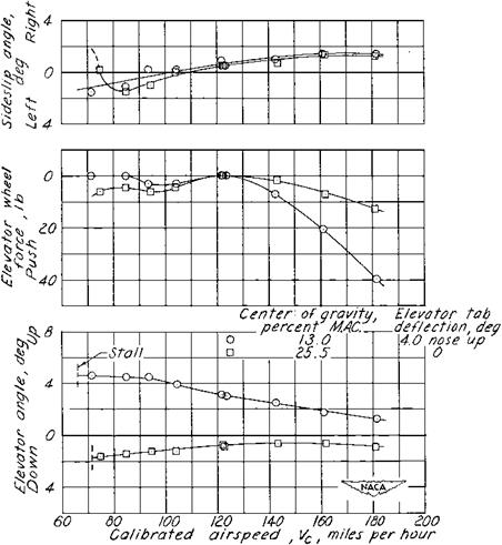
Figure 3.15 The venerable Douglas DC-3 exhibits static longitudinal instability in the normal rated power, clean configuration, at an aft center of gravity position of 25.5 percent MAC. (From Assadourian and Harper, NACA TN 3088, 1953)

level of the most basic stability of them all, static longitudinal stability, as measured by the elevator angles required for steady flight at various airspeeds. This form of stability is often called stick-fixed stability.

The Spitfire shows neutral stick-fixed stability under all flight conditions. The DC-3 is stable only in power-off glides or with cruise power. With normal rated power or in a power approach condition at aft loadings, increasing amounts of down elevator are needed as the airspeed is reduced, along with push column forces (Figure 3.15). For both airplanes there are other less striking deviations from NACA and military stability and control specifications. What should be made from all of this?

The Spitfire and DC-3 cases should not furnish an excuse to dismiss flying qualities requirements. It is reasonable to assume that if the Spitfire and DC-3 were longitudinally stable under all flight conditions, both of these fine airplanes would have been even better. In fact, the Spitfire Mark 22, developed at the end of the war, had a 27 percent increase in tail areas and flew “magnificently,” according to one account. The bottom line is that

nobody has ever found it feasible to run definitive, statistically valid experiments on the value of good flying qualities in terms of reducing losses in accidents or success in military missions. Instead, we rely on common sense. That is, it is highly plausible that good handling qualities in landing approach conditions will reduce training and operational accidents and that precise, light, effective controls will improve air-to-air combat effectiveness. That plausibility is essentially what energizes the drive for good flying qualities, in spite of apparent inconsistencies, such as for the Spitfire and DC-3.

Mechanical Control System Design Details

Connections between a pilot and the airplane’s control surfaces are in a rapid state of evolution, from mechanical cables or push rods, to electrical wires, and possibly to fiber optics. Push rod mechanical systems have fallen somewhat into disuse; flexible, braided, stainless steel wire cable systems are now almost universal. In an unpublished Boeing Company paper, William H. Cook reviews the mature technology of cable systems:

The multi-strand 7×19 flexible steel cables usually have diameters from 1/8 to 3/16 inch.

They are not easily damaged by being stepped on or deflected out of position. They are

usually sized to reduce stretch, and are much over-strength for a 200-pound pilot force.

The swaged end connections, using a pin or bolt and cotter pin, are easily checked. The

turnbuckles which set tension are safety-wired, and are easily checked. A Northwest Airlines early Electra crashed due to a turnbuckle in the aileron system that was not secured with safety wire wrap.

Since the cable between the cockpit and the control is tensioned, the simplest inspection is to pull it sideways anywhere along its length to check both the tension and the end connections. In a big airplane with several body sections this is good assurance. To avoid connections at each body section joint, the cable can be made in one piece and strung out after joining the sections. The avoidance of fittings required to join cable lengths also avoids the possibility of fittings jamming at bulkheads. Since the cable is rugged, it can be installed in a fairly open manner…. Deterioration of the cables from fatigue, as can happen in running over pulleys, or from corrosion, can be checked by sliding a hand over its length. If a strand of the 7×19 cable is broken, it will “draw blood.”

A recurrent problem in all mechanical flight control systems is possible rigging in reverse. This can happen on a new airplane or upon re-rigging an old airplane after disassembly. Mod­ern high-performance sailplanes are generally stored in covered trailers and are assembled only before flying. Sailplane pilots have a keen appreciation of the dangers of rigging errors, including reversals. Preflight checks require the ground crew to resist pilot effort by holding control surfaces and to call out the sense of surface motions, up or down, right or left.

A few crossed cable control accidents have occurred on first flights. The aileron cables were crossed for the first flight of Boeing XB-29 No. 2, but the pilot aborted the takeoff in time. Crossed electrical connections or gyros installed in incorrect orientations are a more subtle type of error, but careful preflight procedures can catch them, too.

Later Developments

An interesting inertial coupling development that came after the great rush of interest in the 1950s was the finding that moderate amounts of sideslip could add to the problem (Stengel, 1975). Perturbation motions about combined sideslip and rolling equi­librium solutions are less stable than perturbations about pure rolling motions.

Also important to the inertial coupling problem are some developments in related fields of airplane dynamics. Chapter 9, on “Spinning and Recovery,” notes the advent of the advanced bifurcation analysis method for study of stall-spin divergence, steady spinning, and wing rock. Bifurcation analysis is also able to predict jump phenomena in rolls or two equilibrium states for the same control surface angles (Schy and Hannah, 1977).

The 1977 study by Schy and Hannah was extended a year later to include nonlinear variations of the stability derivatives with angle of attack (Young, Schy, and Johnson, 1978). The authors correctly observed that the main utility of the bifurcation analysis method as applied to inertial coupling in rolls is to predict the flight conditions and control surface angles for which jumps may occur. These combinations should be examined in detail in complete time history solutions.

P-47 Dive Tests at Wright Field

The Republic P-47 Thunderbolt was, like the P-38 Lightning, an important fighter airplane of World War II. Like the P-38, the P-47 had a supercharged engine and could climb to altitudes of about 35,000 feet and reach high enough airspeeds in dives to have com­pressibility effects on stability and control. The P-47 experience was sufficiently different

P-47 Dive Tests at Wright Field

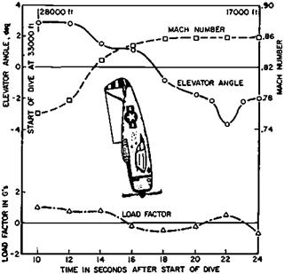
Figure 11.4 A Republic P-47 Thunderbolt fails to respond to 4 degrees of up-elevator in a dive at a Mach number of 0.86. (From Perkins, Jour. of Aircraft, July-Aug. 1970)

from the P-38’s to merit retelling (Perkins, 1970). Following split S entries to vertical dives at 35,000 feet, the P-47’s nose would go down beyond vertical. No recovery seemed pos­sible even with full-back stick and nose-up tab (Figure 11.4). At 15,000 feet high normal acceleration would suddenly come on, and airplanes would recover at 20,000 feet, with bent wings.

Three possible reasons for this were examined in a 1943 conference held at the NACA Langley Laboratory:

1. ice formation on the elevator hinges at 35,000 feet;

2. elevator hinge binding due to loads;

3. Mach number effects on stability and control.

As Perkins recalls, it was Theodore Theodorsen, the eminent NACA mathematician and flutter theorist who championed ice on the hinges as a possible cause for the problem. The NACA structures researcher Richard V Rhode proposed elevator hinge binding as the cause. Robert Gilruth and the forceful John Stack claimed correctly that it was all transonic aerodynamics. Quoting from the Perkins paper:

It became obvious that one simple test would resolve the major difference in the theories. When the pilot pulled on the stick, did the elevator go up or didn’t it? If it didn’t go up, then one of the first two theories would be correct; but if the elevator did go up and the airplane did not respond as it should, then the third theory would be the most likely answer.

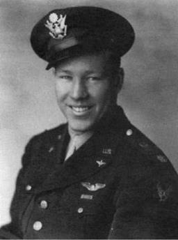
The U. S. Air Corps at Wright Field agreed to run these tests and attempts were made to sign up a test pilot to perform the experiment. None of the contract test pilots were very anxious to do this and would have agreed only at very high fees. The problem was resolved when one of the Air Corps’s strongest and ablest test pilots, [Capt] P. [Perry] Ritchie [Figure 11.5] said he would perform the tests for nothing. He performed some thirty dive tests on an instrumented P-47 and his reward was an Air Medal.

P-47 Dive Tests at Wright Field

Figure 11.5 Capt. Perry Ritchie (1918-1944), the courageous U. S. Air Corps test pilot who made 30 test dives in the P-47 Thunderbolt. (USAF photo)

It was found at once that the elevator did go up to the predicted angle. However, while at that high airspeed the measured amount of elevator angle should have produced 20 to 30 g, the actual response was about 0.5 g, which appeared to the pilot as no response at all. This behavior was also found later by Republic Corporation test pilots. The P-47 was clearly experiencing the same Mach number phenomena as did the P-38. Compressibility burble on the inboard wing sections led to lift curve slope reductions and reductions in rate of change in downwash over the horizontal tail. This caused an increase in longitudinal static stability and a nose-down trim shift.

Rudder Lock and Dorsal Fins

Rudder lock occurs at a large angle of sideslip when reversed rudder aerodynamic hinge moments peg the rudder to its stop. The airplane will continue to fly sideslipped, rudder pedals free, until the pilot forces the rudder back to center or rolls out of the sideslip with the ailerons. Aerodynamic hinge moments can peg the rudder against its stops so securely as to defy the pilot’s efforts at centering. In that case recovery by rolling or pulling up to reduce airspeed are the only options.

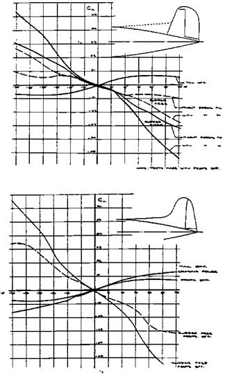
Two things must happen before an airplane is a candidate for rudder lock. Directional stability must be low at large sideslip angles and rudder control power must be high. The relative size of the fuselage and vertical tail determines the general level of directional stability. Directional stability is reduced at large sideslip angles when the fin stalls. The sideslip angle or fin angle of attack (considering sidewash) at which the fin stalls de­pends on the fin aspect ratio. Unfortunately, tall, efficient, high-aspect-ratio fins stall at low fin angles of attack. As a general rule, fin stall occurs at sideslip angles of about 15 degrees.

Unlike normal wings, whose lift is proportional to angle of attack until near the stall, the lift of very low-aspect-ratio rectangular wings is proportional to the square of the angle of attack (Bollay, 1937). There is very little lift generated in the low angle of attack range. However, the angle of attack for stall is increased greatly, reaching angles as high as 45 degrees.

What this means is that a two-part vertical tail is an efficient way to avoid loss in directional stability at large sideslip angles and rudder lock. One part is a high-aspect-ratio vertical tail, which can provide directional stiffness in the normal flight regime of low side­slip angles and give good Dutch roll damping and suppression of aileron adverse yaw. The other part is a low-aspect-ratio dorsal fin, with a reasonably sharp edge, which will carry very little lifting load in the normal flight regime. However, at a sideslip angle where the high-aspect-ratio fin component stalls, the dorsal fin can become a strong lifting surface, maintaining directional stability.

Returning to the role of the rudder, large rudder areas and control power are needed for two-engine airplanes with wing-mounted engines, for the condition of single-engine failure at low airspeeds. This is especially true for propeller-powered airplanes, since full-throttle propeller thrust is highest at low airspeeds, and wing-mounted engines tend to be further outboard than for jets, to provide propeller-fuselage clearance.

Although a four-engine rather than a two-engine airplane, rudder lock was experienced on the Boeing Model 307 Stratoliner, with its original vertical tail. This occurred during an inadvertant spin. From William H. Cook (1991):

On a demonstration flight for KLM and TWA, the KLM pilot applied rudder at low speed. The rudder locked full over in the spin, and the control forces on the rudder were too high [to center it]. Wind tunnel tests showed that a long dorsal fin would prevent the rudder locking over. A hydraulic servo on the rudder was also added.

The addition of a dorsal fin to the Stratoliner and a reduction in rudder area corrected the problem (Figure 14.13) (Schairer, 1941). George Schairer recently commented that he was unaware of the true inventor of dorsal fins, but that a member of the GALCIT 10-foot tunnel staff might have installed one during tests of one of the Douglas airlin­ers. Small dorsal fins appeared earlier than on the Stratoliner, notably on the Douglas DC-3, first produced in 1935, and on the Douglas DC-4, which had its first flight in 1938.

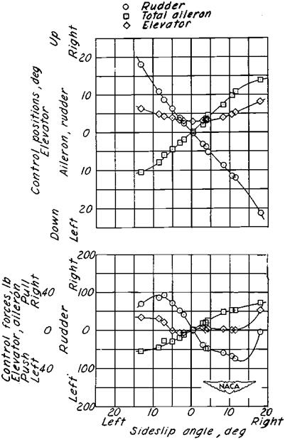
In spite of the small dorsal fin installed on the DC-3, that airplane is still subject to rudder lock in all configurations with power on (Figure 14.14). JohnA. Harper flew a U. S. Air Force C-47B, the military version of the DC-3, in NACA flying qualities tests in 1950. Harper later speculated that rudder lock might have contributed to some puzzling DC-3 accidents resulting from loss of power on one engine, followed by a stall and spin. In these strange

Rudder Lock and Dorsal Fins

Figure 14.13 The variation of yawing moment coefficient with sideslip angle for the Boeing Stra – toliner with original vertical tail (above) and revised vertical tail and dorsal fin (below). Rudder-free cases are shown by the dashed lines. With the original tail, adverse yawing moment due to the ailerons overcomes the low level of restoring moment at large side-slip angles, and there is rudder lock. (From G. S. Schairer, Jour oftheAeo. Sci., May 1941)

accidents, the airplane spun into the operating engine, the reverse of what one would expect. Harper argues that rudder lock and high pedal forces for recovery could have occurred if the pilot overcontrolled with the rudder to turn toward the live engine.

Rudder lock was suspected in the early Boeing 707 airplanes, which had manually operated rudders assisted by spring tabs and internal aerodynamic balance. An Air Force test of the XC-135 tanker version reported rudder lock and an American Airlines crash on Long Island may have been due to rudder lock. As a result, the 707 and KC-135 series of airplanes have powered rudders.

Rudder Lock and Dorsal Fins

Figure 14.14 Incipient rudder lock on the DC-3 airplane. The rudder force has gone to zero at a right sideslip angle of18 degrees. The rudderangle is only21 degrees left, with 9 more degrees of deflection available before reaching the rudder stop of 30 degrees. The rudder locks over at larger rudder and sideslip angles, but these are not reached in this test series because of heavy airplane buffet. (From Assadourian and Harper, NACA TN 3088, 1953)

In addition to the large rudder area requirement for the engine-out condition on multi­engine airplanes, large rudder areas are needed for spin recovery on maneuverable airplanes, to handle heavy crosswinds for airplanes intended to operate out of single-strip airports, and for gliders, to counter adverse aileron yaw. Gliders have a particular adverse yaw problem because their high-aspect-ratio wings have large negative (adverse) values of yaw­ing moment due to rolling at high lift coefficients. Pilots transitioning from light power planes to gliders, or vice versa, find vigorous rudder action in rolls is needed for coordina­tion in gliders, as compared with light planes.

Airplanes in all of these categories might be found with dorsal fins, to prevent rudder lock. For example, the Waco CG-4A and XCG-13 cargo gliders had strong rudder lock before their vertical tails were enlarged and dorsal fins were added. On the other hand, dorsal fins have been used on airplanes as a matter of style rather than for the function of augmenting static directional stability at large angles of sideslip. This can be suspected if dorsal fins are found on airplanes that have large vertical tails at a reasonable tail length, rudders of small to moderate size, and either one or more than two engines.

Pusher Propeller Problems

Although canard airplanes can have propellers in front, in the so-called tractor position, canard propeller-driven aircraft generally wind up with pusher propellers. Thus, in the context of discussing design, stability, and control problems of canards, it is appropriate to bring up some design problems of pusher propellers as well.

A tail-down landing touchdown attitude is often desired, for a minimum energy landing. In fact, many nose landing gears are not expected to take landing impact loads and are noticeably lighter and weaker than main landing gear assemblies. Pusher propellers tend to have relatively small diameters, just to provide clearance for tail-down landings. This is a constraint on propeller design, leading to lower propulsive efficiency. Alternatively, airplanes with pusher propellers tend to have relatively long, heavy main landing gear legs.

Pusher propellers generally act in the wakes of either wings or horizontal tails. While there may be no appreciable propulsive efficiency loss for such arrangements, a distinctive propeller noise generally results, which could be a problem for people on the ground. Pusher propellers have vibration problems, and their engines can have cooling problems.

Finite-Element or Panel Methods in Quasi-Static Aeroelasticity

Analyzing quasi-static aeroelastic effects requires balancing air loads against struc­tural stiffness and mass distributions. Because of the complexity of the problem, only ap­proximate methods were available for many years. The advent of finite-element or panel methods both in structural analysis and in aerodynamics made accurate quasi-static aero – elastic analysis really possible for the first time.

In the aerodynamic finite-element approach, the airplane’s surface is divided into many generally trapezoidal panels, or finite elements. Under aerodynamic and inertial loadings, the structure finds an equilibrium when boundary conditions are satisfied at control points such as the center of the 3/4-chord line of an aerodynamic panel or at the edges of a structural panel. Finite-element methods in structural analysis preceded those for aerodynamic analysis by many years.

Finite-Element or Panel Methods in Quasi-Static Aeroelasticity

Figure 19.8 Effect of dynamic pressure on the dihedral effect of the Douglas XA3D-1 airplane, at two angles of attack. The wing lift is close to zero at a (fuselage) angle of attack of -3 degrees, and there is little wing bending and change in dihedral effect. (From Rodden, AGARD Report 725, 1989)

The earliest aerodynamic finite-element method, called vortex lattice analysis, appears to have been developed independently by two people. Vortex lattice analysis is docu­mented in internal Boeing Company and Swedish Aeronautical Research Institute re­ports by P. E. Rubbert in 1962 and Sven G. Hedman in 1965, respectively, and in a few other reports of the same period. Dr. Arthur R. Dusto and his associates at the Boeing Company combined these structural and aerodynamic finite-element methods into an aero – elastic finite-element system they call FLEXSTAB (Dusto, 1974) in the period 1968 to 1974.

Finite-element methods in quasi-static aeroelasticity require generation of mass, struc­tural influence, and aerodynamic influence matrices. The mass matrix is the airframe mass assigned to each element. The structural influence coefficient matrix transforms deflec­tions at control points in an element to elastic forces and moments at the other elements. The aerodynamic influence coefficient matrix transforms angle of attack at one element to aerodynamic forces and moments acting on the other elements.

It is interesting that the advent of finite-element quasi-static aeroelastic methods coin­cided with the need for methods that account for significant chordwise structural distortions. Quasi-static aeroelastic methods based on lifting line theory were appropriate for flexible airplanes of the Boeing B-47 and Douglas DC-8 generation, subsonic airplanes with long, narrow wings. Proper quasi-static aeroelastic analysis of the lower aspect ratio, complex wing planforms of the Northrop B-2 stealth bomber and supersonic-cruise transport air­planes, requires panel methods.

NASTRAN is a widely used finite-element structural analysis computer program. The MacNeal-Schwendler Corporation’s proprietary version, called MSC/NASTRAN, adds

Finite-Element or Panel Methods in Quasi-Static Aeroelasticity

In this equation:

u = displacement vectors or column matrices К — structural stiffness matrices M = structural mass matrices P = aerodynamic force matrices D = a rigid body mode matrix

Figure 19.9 One form of the NASTRAN quasistatic aeroelastic matrix equations. Additional manipulations are needed to arrive at the unrestrained aeroelastic stability and control derivatives. (From Rodden and Johnson, eds., MSC/NASTRAN Aeroelastic Analysis User’s Guide, 1994)

aerodynamic finite-element models to the existing structural models with splining or inter­polation techniques to connect the two. This version can perform quasi-static aeroelastic analysis (Figure 19.9). This accomplishment is credited to a number of people, including Drs. Richard H. MacNeal and William P Rodden, and E. Dean Bellinger, Robert L. Harder, and Donald M. McLean.