Category Airplane Stability and Control, Second Edition

Spoiler Opening Aerodynamics

Experimental or wind-tunnel studies of rapidly opening upper-wing surface spoil­ers show a momentary increase in lift, followed by a rapid decrease to a steady-state value that is lower than the initial value. At a wind speed of 39 feet per second, the initial increase is over in less than a half-second, and steady-state conditions appear in about 3 seconds (Yeung, Xu, and Gu, 1997). Results from the computational fluid dynamics method known as the discrete vortex method also predict the momentary increase in lift and associate it with a vortex shed from the spoiler upper edge in a direction that increases net airfoil circulation in the lifting direction. A subsequent shed vortex from the wing trailing edge in the opposite direction reduces circulation to the steady-state value. While suggestive, experimental flow visualization results do not exist that confirm this vortex model.

The Yeung, Xu, and Gu experiments show that providing small clearances between the spoiler lower edge and the wing upper surface reduces the momentary increase in lift following spoiler extension. This is consistent with a small shed vortex from the spoiler lower edge of opposite rotation to the vortex shed at the upper edge. A clearance between spoiler and wing surface of this type has also been used to reduce buffet.

The B-52 Elevator Also Has Limited Control Authority

The B-52’s elevator is as narrow in chord as is the rudder. It depends on help from an adjustable stabilizer for long-term trim and airspeed changes. As in the case of the vertical tail, the original Boeing design called for an all-moving horizontal tail, but this was abandoned because of doubts as to hydraulic actuator reliability.

The B-52’sadjustable stabilizer isdriven by two independent hydraulic motorsthrough an irreversible screw jack mechanism. One motor drives the jackscrew and the other the live nut on the driven screw thread (Figure 7.6). The control valve for each hydraulic motor is worked

The B-52 Elevator Also Has Limited Control Authority

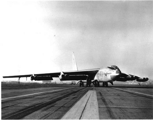
Figure 7.5 B-52 Stratofortress in a crosswind landing attitude. The landing gears are pointed down

the runway while the airplane is yawed to the left, presumably into the relative wind. Crosswind landing gear reduces the need for rudder power. (From Loftin, NASA SP-468, 1985)

either by an electric motor or by a backup cable drive from the cockpit. The electric motors are controlled in turn by the usual push-button arrangement on the pilot’s control yoke.

With all of this redundancy, stabilizer adjustment failures can still occur, but the B-52 is landable in an emergency with elevator control alone, regardless of stabilizer position. Some center of gravity adjustment by fuel pumping is necessary for this to work.

Time Domain-Based Criteria

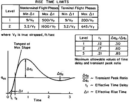
Time domain response specifications get around the need for equivalent systems. A standard time domain response form was used in the 1987 version of the U. S. flying

Time Domain-Based Criteria

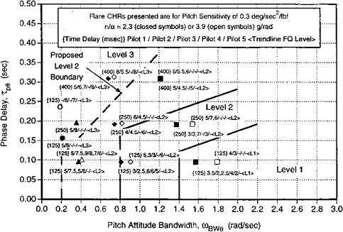
Figure 10.6 Example pitch attitude bandwidth/phase delay criterion, with test results. (From Field and Rossitto, 1999).

Time Domain-Based Criteria

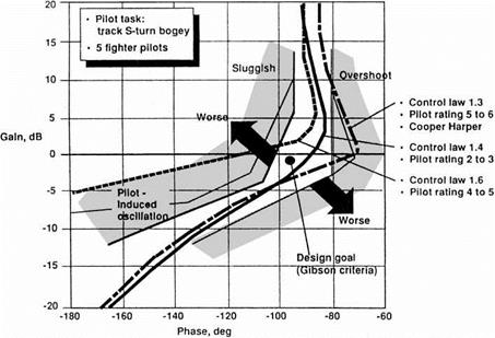
Figure 10.7 Pilot evaluation of pitch response using Gibson Nichols chart template. (From Blight 1996)

Time Domain-Based Criteria

Figure 10.8 Generic pitch rate response to abrupt control input. This type of transient response description has the advantage of applying to high-order stability-augmented as well as unaugmented airplanes. (From Mil Standard MIL-STD-1797, 1987)

qualities standard, MIL-STD-1797 (Figure 10.8). Other time domain response criteria have been proposed, as follows:

The C* Parameter L. G. Malcolm and H. N. Tobie originated the C* parameter, to blend normal acceleration and pitch rate responses to pitch control input. C* is actually a weighted, linear combination of the two responses, akin to the weighted performance indices used in optimization calculations.

The Time Response Parameter Some years later, C. R. Abrams enlarged on the C* parameter approach with a time response parameter that includes time delay in addition to the earlier normal acceleration and pitch rate terms.

Gibson Dropback Criterion This refers to the pitch attitude change following a commanded positive pulse in airplane angle of attack. Pitch attitude increases during the pulse. A pitch attitude decrease after the pulse ends is called a drop – back. A slight dropback is associated with fine tracking. A large or negative dropback (pitch overshoot) creates unsatisfactory pitch short-period behavior.

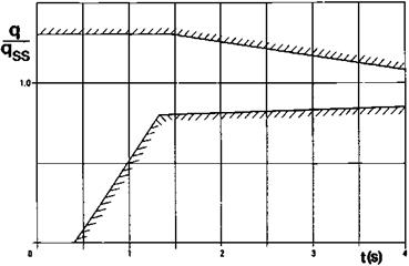
Special Time Response Boundaries Upper and lower boundaries for longitudi­nal response was a still later specification form, used widely for landing approach responses in addition to up-and-away flying. The space shuttle Orbiter’s longitu­dinal control response is governed by such boundaries (Figure 10.9), apparently established in simulation.

Gibson (2000) comments that the upper boundary in particular severely limits rapid acquisition of angle of attack change in response to pitch demand and was responsible for space shuttle touchdown problems. He says further:

Time Domain-Based Criteria

Figure 10.9 An example of a time response boundary. The pitch rate response to a step-type manip­ulator input must lie between the boundaries. Pitch rate response q is normalized by the steady-state value qss. This particular time response boundary applies to the space shuttle Orbiter. (From Mooij, AGARD LS 157, 1988)

The UK HOTOL project (a horizontal take off Shuttle equivalent) was studied at Warton.. .By designing to optimum piloted pitch response dynamics, i. e., with a rapid flight path response and hence considerable pitch rate overshoot, accurate automatic touch­down was easily achieved in simulation.

Further progress in understanding and improving longitudinal maneuverability has made use of closed-loop studies using the human pilot model (see Chapter 21).

Ultralight Airplane Pitch Stability

Conventional ideas about the need for longitudinal static stability are misleading in the case of ultralight airplanes. The reason is that, instead of the normal short – and long – period, or phugoid, modes of motion, four unfamiliar first-order modes may appear. For ex­ample, the Gossamer Condor’s center of gravity is aft of the neutral point, in order to unload somewhat the canard surface. This produces a positive or unstable value for the CMa deriva­tive. As a result, one of the four first-order modes is unstable. However, the corresponding divergence has a time constant of about 1,000 seconds, making it imperceptible to pilots.

Another way to explain the benign pitch behavior of ultralight airplanes flying at centers of gravity behind the neutral point is to consider their maneuvering stability. Maneuvering stability disappears at the maneuver point. The maneuver point of ultralight airplanes tends to be far aft of the neutral point because of high pitch and heave damping levels. For flight at centers of gravity behind the neutral point but ahead of the maneuver point, the machine would have no tendency to diverge unstably in pitch attitude at constant airspeed. Its unstable behavior would require a simultaneous loss of airspeed and nose-up pitch change in level flight, a process that is very slow.

To illustrate the concept of the maneuver point or maneuvering stability, consider an airplane with an unstable gradient in pitching moment with angle of attack, and suppose it to be disturbed nose-up with respect to its flight path. The unstable pitching moment gradient would tend to increase the size of the disturbance, but at the same time the increase of angle of attack would cause the flight path to curve upward if the speed is constant. The upward curvature of the flight path implies an angular velocity in pitch, which is resisted by the aerodynamic damping in pitch.

In the case of the Gossamer aircraft, the stabilizing effect of the pitch damping due to flight path curvature overwhelms the destabilizing gradient of pitching moment with angle of attack. The neutral point is 5 percent ahead of the center of gravity, but the maneuver point is four chord lengths behind the center of gravity, due to the large path curvature for a given angle of attack.

Evolution of the Equations of Motion

There is a reproduction in Chapter 1 of George H. Bryan’s equations of airplane motion on moving axes, equations developed from the classical works of Newton, Euler, and Lagrange. This astonishingly modern set of differential equations dates from 1911. Yet, Bryan’s equations were of no particular use to the airplane designers of his day, assuming they even knew about them.

This chapter traces the evolution of Bryan’s equations from academic curiosities to their present status as indispensable tools for the stability and control engineer. Airplane equations of motion (Figure 18.1) are used in dynamic stability analysis, in the design of stability augmenters (and automatic pilots), and as the heart of flight simulators.

18.1 Euler and Hamilton

One of the problems faced by Bryan in developing equations of airplane motion was the choice of coordinates to represent airplane angular attitude. Bryan chose the system of successive finite rotations developed by the eighteenth-century Swiss mathematician Leonhard Euler, with a minor difference. In Bryan’s words:

In the [Eulerian] system as specified in Routh’s Rigid Dynamics and elsewhere, the axes are first rotated about the axis of z, then about the axis of y, then again about the axis of z. The objection to this specification is that if the system receives a small rotation about the axis of x, this cannot be represented by small values of the angular coordinates.

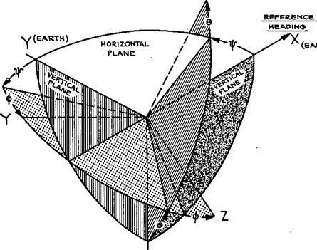
Bryan chose instead to rotate by a yaw angle Ф about the vertical axis, a pitch angle © about the lateral axis, followed by a roll angle Ф about the pitch axis – a sequence that has been followed in the field ever since. However, Bryan’s orthogonal body axes fixed in the airplane are rotated by 90 degrees about the X-axis as compared with modern practice. That is, the Y-axis is in the place of the modern Z-axis, while the Z-axis is the negative of the modern Y-axis (Figure 18.2).

Bryan’s Eulerian angles have served the stability and control community well in almost all cases. However, there were other choices that Bryan could have made that would have avoided a singularity inherent in Euler angles. The singularity shows up at pitch angles of plus or minus 90 degrees, the airplane pointing straight up or straight down. Then the equation for yaw angle rate becomes indeterminate.

The Euler angle singularity at 90 degrees is avoided by the use of either quaternions, invented by Sir W. R. Hamilton, or by direction cosines. The main disadvantage of quater­nions and direction cosines as airplane attitude coordinates is their utter lack of intuitive feel. Flight dynamics time histories calculated with quaternions or direction cosines need to be translated into Euler angles for intelligent use. Except for simulation of airplane or space-vehicle vertical launch or of fighter airplanes that might dwell at these attitudes, the Euler angle singularity at 90 degrees is not a problem.

As the term implies, there are four quaternion coordinates; there are nine direction cosine coordinates. Since, as Euler pointed out, only three angular coordinates are required

to specify rigid-body attitudes, quaternion and direction cosine coordinates have some degree of redundancy. This redundancy is put to good use in modern digital computations to minimize roundoff errors in an orthogonality check. Another advantage to quaternion as compared with Euler angle coordinates is the simple form of the quaternion rate equations, which are integrated during flight simulation. Euler angle rate equations differ from each other, are nonlinear, and contain trigonometric functions. On the other hand, quaternion rate equations are all alike and are linear in the quaternion coordinates.

The nine direction cosine airplane attitude coordinates are identical to the elements of the 3-by-3 orthogonal matrix of transformation for the components of a vector between two

X

Evolution of the Equations of Motion

Z (EARTH)

ORDER OF ROTATIONS

Y, © , Ф

Figure 18.2 The Euler angle sequence in most common use as airplane attitude coordinates in flight dynamics studies. This sequence was defined by B. Melvill Jones in Durand’s Aerodynamic Theory, in 1934. (From Abzug, Douglas Rept. ES 17935, 1955)

coordinate systems. As in the quaternion case, all nine direction cosine rate equations have the advantage of being alike in form, and all are also linear. The direction cosine rate equations are sometimes called Poisson’s equations. Airplane equations of motion using quaternions are common; those using direction cosine attitude coordinates are rare.

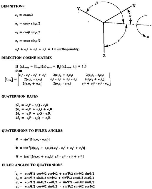
The Euler parameter form of quaternions uses direction cosines to define an axis of rotation with respect to axes fixed in inertial space. A rotation of airplane body axes about that axis brings body axes to their proper attitude at any instant (Figure 18.3). This goes back to one of Euler’s theorems, which states that a body can be brought to an arbitrary attitude by a single rotation about some axis. There is no intuitive feel for the actual attitude corresponding to a set of Euler parameters because the four parameters are themselves trigonometric functions of the direction cosines and the rotation angle about the axis.

The first published report bringing quaternions to the attention of airplane flight simu­lation engineers was by A. C. Robinson (1957). Robinson’s contribution was followed in 1960 by D. T. Greenwood, who showed the advantages of quaternions in error checking nu­merical computations during a simulation. A detailed historical survey of all three attitude coordinate systems is given by Phillips, Hailey, and Gebert (2001). The flight simulation

Evolution of the Equations of Motion

Figure 18.3 The Euler parameter form of quaternions used in some flight simulations to calculate airplane attitude. The upper group of equations defines the Euler parameters in terms of an axis of rotation of XYZ to a new attitude. {x}body are vector components on the rotated axes; {x} earth are the same components on the original axes. Transformations between Euler parameters and Euler angles are given in the lower two sets of equations.

community appears to be divided on the choice between Euler angles and quaternions. In some cases, both are used in different flight simulators within a single organization. However, it is interesting that so many modern digital computations of airplane stability and control continue to use Euler angle coordinates in the 1911 Bryan manner.

Normal Mode Analysis

Normal mode analysis, as applied to aeroelastic stability and control problems, is actually a form of the small oscillation theory about given states of motion. This goes back to the British teacher of applied mechanics E. J. Routh, in the nineteenth century. A body is supposed to be released from a set of initial restraints and allowed to vibrate freely. It will do so in a set of free vibrations about mean axes, whose linear and angular positions remain unchanged. The free vibrations occur at discrete frequencies (eigenfrequencies), in particular mode shapes (eigenvectors).

Of course, the airplane does not vibrate freely, but under the influence of aerodynamic forces and moments. These forces and moments are added to the vibration equations through a calculation of the work done during vibratory displacements. Likewise, the changes in aerodynamic forces and moments due to distortions must have an effect on the motion of mean axes, or what we would call the rigid-body motions.

According to Etkin’s criterion, if the separations in frequency are not large between the vibratory eigenfrequencies and the rigid-body motions such as the short-period longitudinal or Dutch roll oscillations, then normal mode equations should be added to the usual rigid – body equations. Each normal mode would add two states to the usual airframe state matrix (Figure 19.10). A useful example of adding flexible modes to a rigid-body simulation is provided by Schmidt and Raney (2001). Milne’s mean axes are used.

Normal mode aeroelastic controls-coupled analyses were made in recent times for the longitudinal motions of both the Northrop B-2 stealth bomber and the Grumman X-29A research airplane. In both cases, the system state matrix that combines rigid-body, nor­mal mode, low-order unsteady aerodynamic and pitch control system (including actuator dynamic) states was of order about 100 (Britt, 2000).

Gibson Approach

In his 1999 thesis at TU Delft, John C. Gibson proposes a different categorization of PIO from that of McRuer (Sec. 6). In one category are PIOs that arise from conventional low – order response dynamics. The pilot can back out of these by reducing gain or abandoning the task. In this category the lag in angular acceleration following a control input is insignificant, giving the pilot an intimate linkage to the aircraft response.

In the second category are PIOs arising from high-order dynamics in which the pilot is locked in and is unable to back out. High-order dynamics such as excessive linear control law lags or actuator rate and/or acceleration limiting create large lags in acceleration response, disconnecting the pilot from the response.

In the first category, solutions can be developed assuming only the simplest of pilot models. The basic idea is that fly-by-wire technology can be used to shape the response so that the control laws provide the McRuer crossover model for the airplane-pilot combina­tion, with the pilot required only to provide simple gains. Of course, other factors such as sensitivity, attitude and flight path dynamics, and mode transitions must be considered.

The second category, involving high-order dynamics, requires detailed examination of the evidence to define the limit of high-order effects that can be tolerated. Stop-to-stop stick inputs at critical frequencies must be evaluated.

Preface

After raising student enthusiasm by a particularly inspiring airplane stability and control lecture, Professor Otto Koppen would restore perspective by saying, “Remember, airplanes are not built to demonstrate stability and control, but to carry things from one place to another.” Perhaps Koppen went too far, because history has shown over and over again that neglect of stability and control fundamentals has brought otherwise excellent aircraft projects down, sometimes literally. Every aspiring airplane builder sees the need intuitively for sturdy structures and adequate propulsive power. But badly located centers of gravity and inadequate rudder area for spin recovery, for example, are subtleties that can be missed easily, and have been missed repeatedly.

Before the gas turbine age, much of the art of stability and control design was devoted to making airplanes that flew themselves for minutes at a time in calm air, and responded gracefully to the hands and feet of the pilot when changes in course or altitude were required. These virtues were called flying qualities. They were codified for the first time by the National Advisory Committee for Aeronautics, the NACA, in 1943. Military procurement specifications based on NACA’s work followed two years later.

When gas turbine power arrived, considerations of fuel economy drove airplanes into the stratosphere and increased power made transonic flight possible. Satisfactory flying qualities no longer could be achieved by a combination of airplane geometry and restric­tions on center-of-gravity location. Artificial stability augmenters such as pitch and yaw dampers were required, together with Mach trim compensators, all-moving tailplanes, and irreversible surface position actuators. At roughly the same time, the Boeing B-47 and the Northrop B-49 and their successful stability augmenters marked the beginning of a new age.

Since then much of the art and science that connected airplane geometry to good low – altitude flying qualities have begun to be lost to a new generation of airplane designers and builders. The time has come to record the lore of earlier airplane designers for the benefit of the kit-built airplane movement, to say nothing of the survivors of the general-aviation industry. Accordingly, this book is an informal, popular survey of the art and science of airplane stability and control. As history, the growth of understanding of the subject is traced from the pre-Wright brothers’ days up to the present. But there is also the intention of preserving for future designers the hard-won experience of what works and what doesn’t. The purpose is not only to honor the scientists and engineers who invented airplane stability and control, but also to help a few future airplane designers along the path to success.

If this work has any unifying theme, it is the lag of stability and control practice behind currently available theory. Repeatedly, airplanes have been built with undesirable or even fatal stability and control characteristics out of simple ignorance of the possibility of using better designs. In only a few periods, such as the time of the first flights near the speed of sound, theoreticians, researchers, and airplane designers were all in the same boat, all learning together.

The second edition of this book brings the subject up to date by including recent de­velopments. We have also used the opportunity to react to the numerous reviews of the first edition and to the comments of readers. One theme found in many reviews was that the first edition had neglected important airplane stability and control work that took place outside of the United States. That was not intentional, but the second edition has given the authors a new opportunity to correct the problem. In that effort, we were greatly aided by the following correspondents and reviewers in Canada, Europe, and Asia: Michael V Cook, Dr. Bernard Etkin, Dr. Peter G. Hamel, Dr. John C. Gibson, Bill Gunston, Dr. Norohito Goto, Dr. Gareth D. Padfield, Miss A. Jean Ross, the late Dr. H. H. B. M. Thomas, and Dr. Jean-Claude L. Wanner.

The interesting history of airplane stability and control has not lacked for attention in the past. A number of distinguished authors have presented short airplane stability and control histories, as distinct from histories of general aeronautics. We acknowledge particularly the following accounts:

Progress in Dynamic Stability and Control Research, by William F. Milliken, Jr., in the September 1947 Journal of the Aeronautical Sciences.

Development of Airplane Stability and Control Technology, by Courtland D. Perkins, in the July-August 1970 Journal of Aircraft.

Eighty Years of Flight Control: Triumphs and Pitfalls of the Systems Approach, by Duane T McRuer and F. Dunstan Graham, in the July-August 1981 Journal of Guidance and Control.

Twenty-Five Years of Handling Qualities Research, by Irving L. Ashkenas, in the May 1984 Journal of Aircraft.

Flying Qualities from Early Airplanes to the Space Shuttle, by William H. Phillips, in the July-August 1989 Journal of Guidance, Control, and Dynamics.

Establishment of Design Requirements: Flying Qualities Specifications for Amer­ican Aircraft, 1918-1943, by Walter C. Vincenti, Chapter 3 of What Engineers Know and How They Know It, Johns Hopkins University Press, 1990.

Evolution of Airplane Stability and Control: A Designer’s Viewpoint, by Jan Roskam, in the May-June 1991 Journal of Guidance.

Recollections of Langley in the Forties, by W. Hewitt Phillips, in the Summer 1992 Journal of the American Aviation Historical Society.

Many active and retired contributors to the stability and control field were interviewed for this book; some provided valuable references and even more valuable advice to the authors. The authors wish to acknowledge particularly the generous help of a number of them. Perhaps foremost in this group was the late Charles B. Westbrook, a well-known stability and control figure. Westbrook helped with his broad knowledge of U. S. Air Force – sponsored research and came up with several obscure but useful documents. W. Hewitt Phillips, an important figure in the stability and control field, reviewed in detail several book chapters. His comments are quoted verbatim in a number of places. Phillips is now a Distinguished Research Associate at the NASA Langley Research Center.

We were fortunate to have detailed reviewsfrom two additional experts, William H. Cook, formerly of the Boeing Company, and Duane T. McRuer, chairman of Systems Technology, Inc. Their insights into important issues are used and also quoted verbatim in several places in the book. Drs. John C. Gibson, formerly of English Electric/British Aerospace, and Peter G. Hamel, director of the DVL Institute of Flight Research, Braunschweig, were helpful with historical and recent European developments, as were several other European and Canadian engineers.

Jean Anderson, head librarian of the Guggenheim Aeronautical Laboratory at the California Institute of Technology (GALCIT) guided the authorsthrough GALCIT’simpres – sive aeronautical collections. All National Advisory Committee for Aeronautics (NACA) documents are there, in microfiche. The GALCIT collections are now located at the Institute’s Fairchild Library, where the Technical Reference Librarian, Louisa C. Toot, has been most helpful. We were fortunate also to have free access to the extensive stability and control collections at Systems Technology, Inc., of Hawthorne, California. We thank STI’s chairman and president, Duane T. McRuer and R. Wade Allen, for this and for very helpful advice.

The engineering libraries of the University of California, Los Angeles, and of the University of Southern California were useful in this project. We acknowledge also the help of George Kirkman, the volunteer curator of the library of the Museum of Flying, in Santa Monica, California, and the NASA Archivist Lee D. Saegesser.

In addition to the European and Asian engineers noted previously, the following people generously answered our questions and in many cases loaned us documents that added materially to this work: Paul H. Anderson, James G. Batterson, James S. Bowman, Jr., Robert W. Bratt, Daniel P. Byrnes, C. Richard Cantrell, William H. Cook, Dr. Eugene E. Covert, Dr. Fred E. C. Culick, Sean G. Day, Orville R. Dunn, Karl S. Forsstrom, Richard G. Fuller, Ervin R. Heald, Robert K. Heffley, Dr. Harry J. Heimer, R. Richard Heppe, Bruce E. Jackson, Henry R. Jex, Juri Kalviste, Charles H. King, Jr., William Koven, David A. Lednicer, Dr. Paul B. MacCready, Robert H. Maskrey, Dr. Charles McCutchen, Duane T McRuer, Allen Y. Murakoshi, Albert F. Myers, Dr. Gawad Nagati, Stephen Osder, Robert O. Rahn, Dr. William P Rodden, Dr. Jan Roskam, Edward S. Rutowski, George S. Schairer, Roger D. Schaufele, Arno E. Schelhorn, Lawrence J. Schilling, Dr. Irving C. Statler, and Dr. Terrence A. Weisshaar.

Only a few of these reviewers saw the entire book in draft form, so the authors are responsible for any uncorrected errors and omissions.

This book is arranged only roughly in chronological order. Most of the chapters are thematic, dealing with a single subject over its entire history. References are grouped by chapters at the end of the book. These have been expanded to form an abbreviated or core air­plane stability and control bibliography. The rapid progress in computerized bibliographies makes anachronistic a really comprehensive airplane stability and control bibliography.

Malcolm J. Abzug E. Eugene Larrabee

Airplane Stability and Control, Second Edition

Power Effects on Stability and Control

The World War II period 1939-1945 coincided almost exactly with the appearance of power effects as a major stability and control problem. Grumman Navy fighters of that period illustrate the situation. World War II opened with the F4F Wildcat as the Navy’s first-line fighter and ended with the debut of the F8F Bearcat. The external dimensions of the two aircraft were almost identical, but the F8F’s engine was rated at 2,400 horsepower, compared to 1,350 horsepower for the F4F.

In unpublished correspondence, W Hewitt Phillips remarks that the appearance of power effects as a major stability and control problem was not entirely the result of growth in engine power:

these effects have been with us since World War I, but weren’t serious then because of the light control forces required to offset these effects, resulting from the low speeds and smaller size of these airplanes. The power effects in terms of thrust and moment coefficients were probably of the same order as in the case of the World War II fighters. These effects would have been somewhat reduced because of the short nose moment arm of these planes, and because of the lower lift coefficients due to the lack of high lift flaps.

The further growth in power and stability effects on military propeller-driven aircraft was of course interrupted by the advent of jets, with a different set of power effects on stability and control, generally of a minor nature. This chapter reviews the history of both propeller and jet power effects on stability and control. Although the days of high-powered propeller-driven military aircraft may be ended, their civil counterparts still exist, with a new set of stability and control problems.

Artificial Feel Systems

Since irreversible power controls isolate the pilot from aerodynamic hinge moments, artificial restoration of the hinge moments, or “artificial feel,” is required.

Longitudinal artificial feel systems range in complexity from simple springs, weights, and stick dampers to computer-generated reactive forces applied to the control column by servos.

A particularly simple artificial feel system element is the bobweight. The bobweight introduces mass unbalance into the control circuit, in addition to the unbalances inherent in the basic design. That is, even mass-balanced mechanical control circuits have inertia that tends to keep the control sticks, cables, and brackets fixed while the airplane accelerates around them. Bobweights are designed to add the unbalance, creating artificial pilot forces proportional to airplane linear and angular accelerations. They also have been used on airplanes without irreversible power controls, such as the Spitfire and P-51D.

The most common bobweight form is a simple weight attached to a bracket in front of the control stick. Positive normal acceleration, as in a pullup, requires pilot pull force to overcome the moment about the stick pivot of increased downward force acting on the bobweight. There is an additional pilot pull force required during pullup initiation, while the airplane experiences pitching acceleration. The additional pull force arises from pitch­ing acceleration times the arm from the center of gravity to the bobweight. Without the pitching acceleration component, the pilot could get excessive back-stick motions before the normal acceleration builds up and tends to pull the stick forward.

In the case of the McDonnell Douglas A-4 airplane’s bobweight installation, an increased pitching acceleration component is needed to overcome overcontrol tendencies at high airspeeds and low altitudes. A second, reversed bobweight is installed at the rear of the airplane. The reversed bobweight reduces the normal acceleration component of stick force but increases the pitching acceleration component.

Another interesting artificial feel system element is the q-spring. As applied to the Boeing XB-47 rudder (White, 1950) the q-spring provides pedal forces proportional to both pedal deflection and airplane dynamic pressure, or q. Total pressure (dynamic plus static) is put into a sealed container having a bellows at one end. The bellows is equilibrated by static pressure external to the sealed container and by tension in a cable, producing a cable force proportional to the pressure difference, or q. Pilot control motion moves an attachment point of that cable laterally, providing a restoring moment proportional to control motion and to dynamic pressure.

It appears that a q-spring artificial feel system was first used on the Northop XB-35 and B-49 flying wing elevons, combined with a bobweight. Q-spring artificial feel sys­tem versions have survived to be used on modern aircraft, such as the elevators of the Boeing 727, 747, and 767; the English Electric Lightning; and the McDonnell Douglas DC-10. Hydraulic rather than pneumatic springs are used, with hydraulic pressure made proportional to dynamic pressure by a regulator valve. In many transport airplanes the force gradient is further modulated by trim stabilizer angle. Stabilizer angle modulation, acting through a cam, provides a rough correction for the center of gravity position, reducing the spring force gradient at forward center of gravity positions. Other modulations can be introduced.

Advanced artificial feel systems are able to modify stick spring and damper character­istics in accordance with a computer program, or even to apply forces to the stick with computer-controlled servos.