Category An Introduction to THE THEORY OF. AEROELASTICITY

TWO-DIMENSIONAL THIN AIRFOILS IN A STEADY FLOW OF AN INCOMPRESSIBLE FLUID

Let us consider a strip of unit span of a two-dimensional thin airfoil as shown in Fig. 6.1. Let the origin of a right-handed rectangular co­ordinate system be taken at the leading edge of the airfoil profile. Let

TWO-DIMENSIONAL THIN AIRFOILS IN A STEADY FLOW OF AN INCOMPRESSIBLE FLUIDУ

the x axis be taken along the chord line and the у axis be perpendicular to it. The airfoil camber line is described by the equation

у = Y(x) (0 < г < c) (1)

If a steady two-dimensional flow with speed U and an angle of attack a (at large distance from the airfoil) streams past the airfoil, disturbances are introduced into the flow by the airfoil in such a manner that the resultant flow is tangent to the airfoil. According to the aerodynamic theory, the thin airfoil can be replaced by a continuous distribution of vorticity (a vortex sheet). Let the strength of the vorticity over an element of unit length in the spanwise direction and dx in the chordwise direction be y(x) dx. The lift force contributed by the element dx is, according to Joukowsky’s theorem,

dL = pU y(x) dx (2)

The total lift per unit span is therefore

L = puj’y(x) dx (3)

where c is the chord length of the airfoil.

TWO-DIMENSIONAL THIN AIRFOILS IN A STEADY FLOW OF AN INCOMPRESSIBLE FLUID Подпись: (4)

For a thin airfoil of small camber (y(x) < c), the surface of the airfoil differs only infinitesimally from a flat plate. The induced velocity over the airfoil surface, to the first order of approximation, can be calculated by assuming the vortices to be situated on the x axis. The у component of the induced velocity at a point x on the x axis is*

which, to the first order of approximation, is the same as the component of velocity normal to and on the airfoil surface at the chordwise location x.

The slope of the fluid stream on the airfoil is then a + This must be

equal to the slope of the airfoil surface dY/dx. Hence, the boundary condition on the airfoil is

Подпись: (5)v{ dY <x + — — – j – V dx

The vorticity distribution y(x) must be determined from Eq. 5. In addition, the Kutta condition that y(c) = 0 must be satisfied, which is equivalent to the statement that the fluid must leave the trailing edge smoothly.

* This is a Cauchy integral. See footnote on p. 126.

Подпись: Ж = 2(1 Подпись: cos ip) Подпись: (6)

In place of x let a new independent variable ip be introduced so that

Подпись: y = 2UA0 cot Подпись: Sin nip Подпись: (7)

When x varies from 0 to c along the chord, ip varies from 0 to it. The vorticity distribution can be written as*

Substituting (7) into (4), we obtain (see Ref. 1.43 for details)

Подпись:/ Xа

V{ = и 1 – A0 + > An cos nip Equation 5 then implies

CO

Подпись:oc — A0 + An cos nip

Подпись: A„ = - і — cos nip dip 77-Jo dx

The left-hand side is a Fourier series. The coefficients can therefore be determined by the usual method. Multiplying Eq. 9 by cos nip {n = 0, 1, 2, • • •). and integrating from 0 to it, we obtain

From Eqs. 3 and 7, the total lift can be obtained. The result, expressed as the lift coefficient, is

Cz = n(2A0 + A1) (11)

Similarly, the moment about the leading edge, expressed as the moment coefficient, is

(СлАе. = — (л0 + At – І л) = -1 (Аг – АД — CL (12)

A substitution of Eq. 10 into Eqs. 11 and 12 gives

CL = 2тг(а + £0) (13)

(СдЛ. е. = (/Mo —’ 2 e°) ~~ 4 (14)

A form assumed by H. Glauert.1-43

1 dY

£o = ~ ~ – г – (1 – cos y>) dy>

77 Jo UX

Подпись: (15)

Л-~2І г(і-“*ад^

From Eq. 13 it is seen that £0 is the negative of the angle of zero lift and that the theoretical value of dCL/da. is In. The experimental value of dCJda. is somewhat smaller than 2w. It is convenient to write Eq. 13 as

= + є o) (16)

From Eq. 14 it is seen that fi0 — – e° is the moment coefficient at zero

lift and that the lift force acts through the 1/4-chord point (the aerodynamic center). The coefficient of moment about a point at a distance x from the leading edge is

(C. m)x = (СлЛе. + j CL (17)

Differentiating, we obtain

Подпись: (18)

Подпись: where

_ dCL da. dot

Equation 15 shows that, for an airfoil with parabolic or circular camber, the lift is determined by the slope of the camber line at the 3/4-chord point. For such an airfoil can be described by the equation

у = Y(x) = ax(c — x) (19)

where ac2/4 is the maximum camber at the mid-chord point. Hence,

dY о

— = ac — lax — ac cos w dx

So, when x = 3c/4, dY/dx — — ac/2. Now, from Eqs. 15, (20)

1 f” ac

— e0 — — ac cos ip( 1 — cos y>) dy> = ——

TT Jo 2

which is exactly the value of dY/dx at the 3/4-chord point. Therefore the line of zero lift is parallel to the tangent to the airfoil at the 3/4-chord point.

Since the resultant lift force acts through the 1/4-chord point, the vorticity can be regarded as concentrated there in calculating the lift.

The downwash due to a concentrated vortex of strength Г located at the y4-chord point is

____ = пі)

2тг{ф-х) 2тт{ф-х)Ри 2(1/4-ж/с) v

At the 3/4-chord point, x/c = 3/4, we have

– і (»<>»-,. -* + «.-*- (£)„_. СЩ

In other words, if the vorticity is considered as concentrated at the aero­dynamic center (1/4-chord point), the boundary condition for downwash is satisfied at the 3/4-chord point.

We have quoted in § 4.3 that, for a swept or unswept wing of finite span, if the lifting line (the vortex line) is located at the ^-chord line and the downwash condition is satisfied at the 3/4-chord line, the result will give a good approximation to the spanwise lift distribution (Weissinger’s method). Thus the 3/4-chord line seems to have a unique importance. We shall see later that this line is also uniquely significant for oscillating airfoils.

FUNDAMENTALS OF FLUTTER ANALYSIS

This chapter is essentially divided into two parts. In §§ 6.1-6.6 the flutter of a cantilever wing having a straight elastic axis is treated under the assumption of quasi-steady aerodynamic derivatives. In §§ 6.7-12, the quasi-steady assumption is removed, and the analysis is based on the linearized thin-airfoil theory. This division is necessary because the results of the unsteady airfoil theory are so complicated that a great deal of numerical work is required in the solution, and the main analytical features are masked by the calculative complications. On the other hand, the quasi-steady assumption introduces such great simplifications that one will have no difficulty in carrying through a detailed analysis explicitly. Furthermore, the unsteady airfoil theory, as outlined in Chapters 13-15, is quite elaborate. Therefore it seems advantageous to use the quasi­steady theory as an introduction.

Although the quasi-steady assumption is used here chiefly as an intro­duction, the results so obtained may find practical applications for low – speed airplanes. To present a greater variety of methods of attack, Galerkin’s method, as applied to flutter analysis by Grossman,613 is used in the first part, whereas the method of generalized coordinates is used in the second part. The advantage of Galerkin’s method is its direct rela­tionship with the partial differential equations of motion. It is a natural extension of the approach used in § 1.10 for torsion-flexure oscillation of a cantilever beam. The main mathematical feature of the method, par­ticularly in the first approximation, is very similar to the method of generalized coordinates to be explained later in §7.1. It is easy to see how the analysis can be improved by successive approximation, or general­ized so that the results of more accurate aerodynamic theory can be incorporated. However, these refinements will not be discussed. Here, after a review of the thin-airfoil theory in a two-dimensional steady incompressible flow in § 6.1, the quasi-steady aerodynamic coefficients are derived in § 6.2. Then, in § 6.3, the partial differential equations of motion of a straight cantilever wing in a flow are derived, and the possi­bility of flutter and divergence is discussed. In § 6.4 Galerkin’s method for calculating the critical flutter speed is given. This is followed by § 6.5 treating the stability of the wing as the speed of flow varies. In § 6.6 some
condusions regarding the effect of changing several structural parameters on the critical torsion-flexure flutter speed are drawn.[15] [16]

To obtain more accurate answers, the unsteady airfoil theory may be used. To simplify the calculation, we introduce not only the linearization of the hydrodynamic equations, but also the “strip” assumption regarding the finite-span effect: that the aerodynamic force at any chordwise section is the same as if that section were situated in a two-dimensional flow. Information regarding the finite-span effect is still incomplete, and the inclusion of known results in the analysis will introduce tremendous complications in the numerical work. The linearity and strip assumptions will be discussed further in Chapter 7.

The unsteady aerodynamic forces in an incompressible fluid are sum­marized in § 6.7 and are used to study the forced oscillation of a two – dimensional wing in a flow (§ 6.9). The existence of a critical flutter speed is again demonstrated, thus confirming a result obtained earlier in § 6.3. Using the linearized airfoil theory with compressibility effects properly included, the flutter of a two-dimensional wing is analyzed in §6.10. Methods of solving the flutter determinant are discussed in § 6.11. The general problem of determining the critical speed is then discussed in § 6.12. Further remarks about the practical engineering flutter analysis are reserved for the next chapter.

HISTORICAL REMARKS

The earliest study of flutter seems to have been made by Lanchester,5,29 Bairstow, and Fage5,4 in 1916 in connection with the antisymmetrical (fuselage torsion-elevator torsion) flutter of a Handley Page bomber. Blasius,5,8 in 1918, made some calculations after the failure of the lower wing of the Albatross D3 biplane. But the real development of flutter analysis had to wait for the development of the nonstationary airfoil theory, the foundation of which was laid by Kutta and Joukowsky in the period 1902 to 1906. The first numerical calculation of the aerodynamic force on a harmonically oscillating flat plate in a two-dimensional flow was given twenty years later in 1922 by Birnbaum in his thesis at Gottingen. It is well known that PrandtL’s theory of bound vortices was completed in 1918, and was applied by Ackermann to compute the lift of a stationary airfoil. At the suggestion of Prandtl, Birnbaum extended Ackermann’s concept to nonstationary airfoils.13 2’13-3 He obtained numerical results up to a reduced frequency к — 0.12.

About the same time, Wagner15,30 investigated the aerodynamic forces acting on a body that moves suddenly from a stationary configuration to a constant velocity U. The sudden change of angle of attack was also treated.

The next landmark was recorded in 1929. In that year, Glauert15,23,13,14 published data on the force and moment acting on a cylindrical body due to an arbitrary motion, and aerodynamic coefficients of an oscillating wing up to к = 0.5. The calculation was based on Wagner’s method. In the same year, K ussner5,28 extended the method of Birnbaum to obtain the aerodynamic coefficients up to к = 1.5.

In 1934, Theodorsen’s exact solution of a harmonically oscillating wing with a flap was published;13,32 the range of к is then unlimited. Much additional work on aerodynamics appeared since then. It will be re­viewed in Chapters 12-15.

Up to 1934, only a few cases of flutter were recorded. In those days, only airplane wings showed flutter. Aileron mass unbalance and low torsional stiffness of the wing were responsible for most of these accidents.

As early as 1929, the theory of flutter was clarified by KUssner5,28 with respect to many fundamental details—elimination of the time coordinate, substitution of the wing structure by a simple beam, iterative solution of the resulting system, of differential equations, representation of the internal damping by a phase lag in the elastic restoring force, etc. On the other hand, Duncan and Frazer measured5,21,5,25 (1928) flutter derivatives in a wind tunnel and introduced the concept of semirigidity and the methods of matrices. Simple rules of flutter prevention were derived from statis­tical studies both in Germany (by KUssner) and in England (by Roxbee Cox).5,12

From 1934 to 1937, the development of new types of airplane was lively, owing to the arms race of the great powers. Numerous cases of flutter occurred, not only with wings, but also with tail surfaces. The experience of accidents demonstrated the decisive effect of the mass unbalance of the control surfaces, and dynamic mass-balance requirements were generally incorporated into design specifications. In this period, intensive research on flutter was reflected by numerous publications. Many methods of analysis were discussed, and details of aerodynamic forces for control surfaces were published. The two-dimensional problem of airfoil flutter with two degrees of freedom no longer involved any difficulty. Quick solutions (for example, Kassner and Fingado’s graphical method6,15) became available. Two-dimensional problems with three degrees of

freedom—airfoils with flap—were treated satisfactorily. For a three – dimensional wing, Galerkin’s method was applied together with the “strip theory” of aerodynamics. Above all, the theory was confirmed by flutter model tests in wind tunnels.

On the engineering side, ground-vibration tests of an airplane became a routine. The stiffness criteria were generally accepted and proved satisfactory from the point of view of safety.

It was supposed before 1938 that the solution of the flutter problem could be found in flight testing. Unfortunately, in February 1938, during a carefully planned flight test, a four-engined Junkers plane Ju 90 VI crashed, killing all scientists aboard. Since this accident it has been recognized that the inherent difficulties and uncertainties of flight-flutter testing are great. It is only one of many means of investigation, and is justified only if the flutter characteristics are investigated before the test and the dangerous points to be observed are approximately known.

This picture led to an emphasis on theoretical research. With the development of multi-engined wings, twin rudders, auxiliary control surfaces, etc., the two-dimensional analysis had to concede to more complicated three-dimensional analyses. Flutter analysis became more and more a specialized field.

In the period 1937 to 1939, the most frequent cause of flutter accidents was the control-surface tabs. Investigation of the aerodynamically balanced flaps became a central problem. Wind-tunnel tests in this period indicated that, aerodynamically, the “strip theory” gives reasonable accuracy for calculating the critical speed, at least in the incompressible range and for wings of moderate aspect ratio.

In the early part of World War II, most wing flutter cases were due to insufficient aileron mass balance and most tail-surface flutter cases were due to control-surface tabs. Toward the latter part of World War II, airplane speed increased toward the transonic range, and supersonic missiles appeared. Sweptback wings and delta wings attracted the atten­tion of research workers. Steady-state instabilities, especially the control – surface effectiveness of large airplanes, became a real problem. Buffeting, another aeroelastic phenomenon, emerged with new threats because of the shock stall. On the other hand, airplane dynamics, which so far was regarded as a distant relative to aeroelasticity, now strengthened its tie to flutter and other aeroelastic problems.

At present, transonic flight is a daily event, and supersonic flight is a reality. Aeroelastic analysis becomes an organic part of the design. Many problems still await the solution.

DIMENSIONAL SIMILARITY

From a mere knowledge of the number of significant physical param­eters, dimensional analysis can be made to determine the characteristic dimensionless parameters that govern the dynamic similarity (see § 5.2). Without further information, a flutter model and its prototype must be geometrically similar, have similar mass and stiffness distribution, and have the same geometrical attitude relative to the flow. The scale factors must be such that the density ratio ajp, the reduced frequency k, the Mach number M, and the Reynolds number R be the same for the model as for the prototype. These requirements are, of course, exceedingly severe, and hard to be met.

When more specific information about a physical phenomenon is known, certain conditions of geometric, mass, and elastic similarity may be dispensed with, without loss of exactness. Consider the simple example of the bending deflection of a beam. In this case only the flexural stiffness El is of significance. Hence, in constructing a beam model for the purpose of deflection measurements, only the El distribution needs to be simulated; the cross-sectional shape can be distorted if desired. Such freedom in distorting a model greatly simplifies the model design and testing, and will be discussed in greater detail below.

If the differential or integral equation, or equations, governing a physical phenomenon are known, they provide a deeper insight into the laws of similarity than a mere knowledge of the variables that enter the problem, and offer ways in which a distorted model may be used. Illus­trations of this point can be found in many problems.5-62 As a classical example, let us quote the problem of George Stokes, who, in 1850, intro­duced the term “dynamic similarity” into the literature. Stokes’ problem is the motion of a pendulum in a viscous fluid. The basic equation is the Navier-Stokes equation which, for a two-dimensional flow of an incom­pressible viscous fluid with fixed boundaries, may be written as

DIMENSIONAL SIMILARITY(1)

DIMENSIONAL SIMILARITY

where и and v are velocity components in the x and у directions, v is the kinematic viscosity, and со = (dv/dx) — (du/dy) is the vorticity of the fluid. The same differential equation applies to the model:

where the primes refer to model. Let us introduce the scale factors KL, Kt, etc., between dimensions of the model and the prototype, so that

x’ = KLx, yf = K^, t’ = Ktt, / = K, v

со’ = Кшы, и’ = KYu, v’ — KyV

Подпись: dx Подпись: , dx' U = -Г7: DIMENSIONAL SIMILARITY

These scale factors are subject to the kinematic similarity imposed by the relations

Подпись: Ky = KTJKt, Подпись: K,„ - KyjKL Подпись: (4)

so that

The first of Eq. 6 is a kinematic similarity equation 4. The second of Eq. 6 gives the Stokes’ rule for similarity for flows with similar boundary conditions. Using the first of Eqs. 6, the second equation may be written

Подпись:KVKL

Kv

which means, of course, in present terminology, that both the prototype and the model must have the same Reynolds number.*

An alternate procedure, which differs from the previous one only in form and not in basic reasoning, is also commonly used. The idea is to express the differential equations in dimensionless form. Introduce a characteristic length L, a characteristic time T, a characteristic velocity V, a characteristic vorticity £l, and a characteristic number for the kinematic viscosity N. Let x, у, t, etc., be dimensionless quantities so that

x = xL, у = yL, и = HL/T, v = vL/T (8)

t — IT, Q. = dj/T, v — Nv

Then Eq. 1 may be written

Подпись:

DIMENSIONAL SIMILARITY
Подпись: (5) (6)

Эй VT t Эй. Эй NT. /Э2й, Э2Й

зі +Т г Ш + VW ~ иудх2 1 w

Now, for dynamically similar systems, the dimensionless values x, у, l, etc., have the same value for the model as for the prototype. Hence the coefficients VTjL and NT/L2 must be the same for the two systems; i. e.,

VT ГГ NT N’T’

U~ L’2 ( )

where primes refer to model.

The results obtained in Eqs. 6 and 10 are of course identical. The first method has the advantage of requiring fewer notations.

* Stokes anticipated Osborne Reynolds’ results by thirty years. See Langhaar, Ref. 5.62.

As a second example, consider the flexural oscillation of a beam. The governing equation is

Подпись: Э2 Эж2 Подпись: Э2н> pA э^ = 0 DIMENSIONAL SIMILARITY(11)

where p is the density of the beam material, A is the area of beam cross section, and El is the flexural rigidity. Let

A=A»u(j) (12)

Подпись: Э2 lx d2w Эх2 Vі ll Эж2. DIMENSIONAL SIMILARITY Подпись: (13)
DIMENSIONAL SIMILARITY

where A0, rg are the cross-section area and radius of gyration at a reference section, respectively, and / is the length of the beam,/г,/2 being dimension­less functions involving only the dimensionless parameter ж//. Then

Introducing scale factors

x — KLx, l = К if, w — KLw, r q = Kr q^o

(14)

p’ = Kpp, E’ — KeE, t’ = Ktt

where primes refer to model, we have

Подпись:Подпись: (16)[ , (Л avi K2KEKr£ p’ /яЛ Elw’

Эж’2 lJl 1/7 Эж’2.] + KpKLl E’r0’2h 1/7 3t’2 Since Eq. 13 applies as well to the model, we must have

‘K? KEKr 2 KPKL*

This result can be expressed in more familiar form if we write m as the frequency of oscillation and notice that, according to the definition со’ = Кшсо, the scale factor K, n must be the reciprocal of Kt. Then Eq. 16 may be written as

к, лг IX = (17)

Kr о * KE

i. e., the scale factor of the dimensionless parameter

— P (IB)

r0 * E

must be equal to unity. This remains true for all systems expressible by means of /, r0, p, E, f^x/l), and /2(ж//). No restriction to any particular
shape of the cross sections is imposed. Thus the design of a model for the purpose of measuring oscillation modes needs only to simulate /iWO. ЛС*//)» and the parameter (18) above, and is left with complete freedom in selecting cross-sectional shape. Without the auxiliary infor­mation contained in the differential equation, other dimensionless param­eters such as li’rQ would have appeared, and the conclusions would have been more restrictive.

The same reasoning applies to aeroelastic models. As an example, consider the torsion-bending flutter of a cantilever wing in an incom­pressible fluid. If one is satisfied with Theodorsen’s approximation of characterizing flutter condition by the conditions at a “typical” section, the equations describing flutter are given by Eqs. 11 of § 6.9, which are already written in dimensionless form, and hence must apply equally well to the model as to the prototype. An examination of these equations shows that at the flutter condition P0 = Q0 = 0 the following ten dimen­sionless ratios are involved:

/л, xa, cojcoz, ah, ra, cojco, a)a/co, k, hjb, a0 (19)

k, (oJa), and hjba^ are determined by the condition of existence of flutter: the vanishing of the flutter determinant. Hence a model must simulate the first five parameters which are to be evaluated at a typical section of the wing. Any wing having these same dimensionless ratios can be considered as a flutter model of the prototype. In particular, the flutter of a cantilever wing may be simulated by a two-dimensional wing model.

Clearly, model testing intended to conform with more comprehensive theories would require more restrictive similarity laws.

MODEL EXPERIMENTS

Much valuable information can be derived from wind-tunnel model tests. Sometimes the behavior of a specific airplane is so complex that the accuracy of simplified theoretical analysis becomes doubtful; then model testing is almost indispensable in arriving at a sound design. Model testing is often used to determine the optimum location of engines or fuel tanks, and other design parameters.

Because of the requirements on geometrical, kinematical, and dynamic similarity, wind-tunnel flutter models are often quite expensive and difficult to construct. Elaborate techniques of model construction and test instrumentation have been evolved in the past decades.5-fi6~6-72 In recent years attention is called to the method of support of the model in the wind tunnel. For example, the rigid-body degrees of freedom (trans­lation and rotation of the airplane as a whole), may have important effects on the flutter of swept wings and tails. Yet it is impractical in model tests to allow all the degrees of freedom corresponding to free flight conditions. Some simplification is achieved by separating the constituent oscillations of the airplane into symmetric and antisymmetric types and examining them separately.

The critical condition can be found by observing either the free oscilla­tion of the structure following an initial disturbance, or the response of the structure to an external periodic excitation. In the former method, the airspeed is increased until there results a maintained oscillation of a specific amplitude in a chosen degree of freedom. In the second method, one or several exciters (e. g., eccentric rotating masses, air pulse exciter, etc.) are used to excite the oscillation. At each airspeed, the amplitude response is recorded for varying exciter frequencies. The critical flutter condition is specified as the extrapolated airspeed at which the amplifica­tion becomes very large.

DYNAMIC MASS BALANCING*

Since purely translational, purely rotational, and purely control-surface oscillations are stable in most cases, it is clear that a key to flutter pre­vention is to break up any coupling between the various degrees of freedom.

DYNAMIC MASS BALANCING*

Consider a two-dimensional wing of infinite torsional rigidity fitted with an aileron whose center of mass lies behind the hinge line. If this wing is initially at rest and is suddenly given an upward motion, the aileron will tend to lag behind the wing to produce a relationship as shown in Fig. 5.3.

Thus an aileron motion is induced by a vertical motion of the wing by inertia force. This is called an inertia coupling. If the aileron center of mass lies on the hinge line, the inertia coupling will vanish, but the aileron motion may still be excited by the vertical motion because a nonvanishing aerodynamic moment about the hinge line may exist. This is called an aerodynamic coupling. Finally, some elastic linkage may exist so that a vertical deflection causes the aileron to rotate, thus forming an elastic coupling. Similar terms are used for the interconnections between other degrees of freedom, t

An airplane designer has only a limited control over the elastic and aerodynamic couplings, but inertia coupling is more controllable. Since the critical flutter speed is often very sensitive to inertia coupling, a careful consideration of “dynamic mass balancing” can be very rewarding.

* Much of the concept of dynamic mass balancing is due to von Baumhauer and Koning,5-6 who, in 1923, gave results of wind-tunnel tests in which flutter had been eliminated by adding weights to the paddle balance then used for aerodynamic balance.

t A coupling between the wing and aileron can be broken by using a rigid, irreversible control system, i. e., one in which the aileron is not free to rotate.

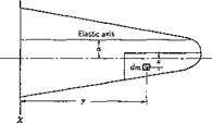
Consider first the flexure-aileron coupling of a cantilever wing. The inertia coupling can be broken if it is possible to arrange the mass distri­bution in such a way that the inertia force due to bending induces no rotational moment about the aileron hinge line. An aileron with mass distribution so arranged is said to be dynamically mass-balanced with respect to flexural motion. Otherwise it is mass-unbalanced. A measure of the mass unbalance is the product of inertia of the aileron about two perpendicular axes, one coinciding with the aileron hinge line, the other corresponding approximately to the wing root.5,20 Let an aileron (Fig. 5.4) be mounted on a hinge line Y, which in turn is mounted rigidly on a wing oscillating about an axis X (assumed perpendicular to Y). The

DYNAMIC MASS BALANCING*

Fig. 5.4. Notations for Aileron mass balance.

inertia force acting on any element of the aileron is proportional to the amplitude of oscillation of that element. If the aileron is perfectly rigid, and the wing oscillates as a rigid body as if it were hinged about the X axis, the acceleration will be proportional to the distance y, and the inertia moment about the aileron hinge line due to an element of mass dm will be proportional to x у dm, where x is the distance of the element dm behind the aileron hinge line. Hence, the total moment is proportional to the product of inertia of the mass of the aileron:

Jxv = fay dm

where the integral is taken over the entire aileron. If Jxy = 0, the inertia coupling is eliminated for the mode of oscillation assumed. In practice, Jxy seldom vanishes. As a measure of the mass unbalance, a non – dimensional “dynamic-balance coefficient”

_________ Jxy________

Mass x area of aileron

is introduced by Roche5-3®

In a modern sense, mass balancing means the best arrangement of masses. For an airplane the location of engines, fuel tanks, radar equip­ment, and so on has a profound influence on the critical flutter condition.

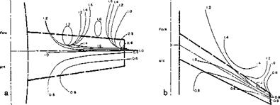
As an example, Figure 5.5 shows the results of a systematic study of the effect of engine locations on the flutter speed of airplanes with unswept and swept wings by means of an electric analog computation. A point on the contour curves of constant flutter speed represents the actual location of the center of gravity of the added mass, and the numbers shown refer to unity based on the flutter speed of the bare wing, without any added mass.

DYNAMIC MASS BALANCING*

Fig. 5.5. Contours of constant flutter speed for (a) unswept and (b) swept tapered wing showing effect of concentrated mass location. Symmetric Flutter. (From С. H. Wilts, “Incompressible Flutter Characteristics of Representative Aircraft Wings.” NACA Tech. Note 3780.)

Thus an engine whose center of gravity is located at a point on a contour labeled 1.4 will improve the flutter characteristics of the bare wing by raising its flutter speed by a factor of 1.4. A knowledge of such trend curves is of great value to the engineer; but such accurate information certainly cannot be given by a simple criterion. It is a general practice in airplane design to start flutter analysis at an early stage, so that certain decisions such as the location of engines and fuel tanks, etc., can be made.

Mass balancing is extremely critical for rockets and satellites. For artificial satellites the mass distribution reacts with gravity gradient and influences the guidance and control. Moving masses are employed to control the damping of a satellite. Active motion of masses makes the system nonconservative. For example, in Ref. 5.74 the author considered the stability of a spinning space station due to periodic motions of the crew. Instability may occur if the period of an astronaut’s motion bears certain ratios to the half-period of the spin of the satellite. If he moves back and forth along the radius of a circular, planar satellite, instability will occur when the period of his motion is approximately an integral multiple of the half-period of the satellite spin. A similar conclusion holds if the astronauts move with constant speed or oscillate periodically in circumferential direction. The heavier the moving masses or the larger their amplitude of motion, the wider is the region of instability.

. THE EXTRACTION OF ENERGY FROM AIRSTREAM

Since flutter is an oscillation induced by the aerodynamic forces without any external source of energy other than the airstream, it is possible only if the oscillating body, the mean position of which is assumed stationary, can extract energy from the airstream.* Hence, the possibility of flutter can be discussed by considering the energy relation.

An oscillation will be called aerodynamically unstable if the oscillating body gains energy from the airstream in completing a cycle. If the oscil­lating body has neither external excitation nor internal friction, then the aerodynamic instability can be identified with flutter. Internal friction dissipates energy, external excitation imposes a source of energy exchange; both modify the kinematic relations (the amplitude ratio and phase relationship between various degrees of freedom) of the oscillation of an aeroelastic system. Hence when there is external excitation or internal

* The inertia force and the elastic force are both conservative and do not contribute any net gain or loss of energy in each complete cycle of motion.

friction, the aerodynamic instability alone cannot be directly identified with flutter.

Consider an airfoil performing a vertical translatory oscillation with a constant amplitude h0. Let the vertical displacement be described by the expression

h = hQeiad (1)

We shall define h as positive downward. The speed of downward motion is therefore

h = icoh0eiwt (2)

where a dot indicates a differentiation with respect to time. If h were a constant, the downward motion will induce a lift force L0 on the airfoil:

Подпись:Lo==2 pU8-d^U

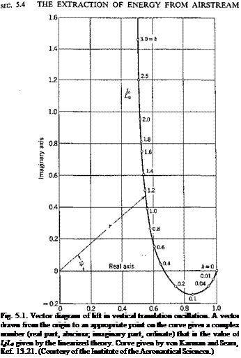
where pU2 is the dynamic pressure and S is the wing area. The lift is defined as positive upward in the usual sense. When the airfoil is oscil­lating, the true instantaneous lift acting on the airfoil differs from L0 both in magnitude and in phase. Let us call L0 the quasi-steady lift and write the true instantaneous lift as

L = (4)

Then r represents the ratio of the absolute value of the instantaneous lift to that of the quasi-steady lift, and if the phase angle by which the actual lift leads the quasi-steady value. The quantities r and if depend on the reduced frequency k, the Mach number M, and the Reynolds number R. For a nonviscous incompressible fluid, r and if are functions of к alone. The ratio L/L0 — гегу> can be plotted as vector with length r and angle ip. Such a vector diagram, for a flow of an incompressible fluid (M = 0), with к as a parameter, is given in Fig. 5.1. The theoretical derivation of this diagram will be given in Chapter 13.

When the airfoil moves through a distance dh, the work done by the lift is, in real variables,

dW = — Ldh= —Lhdt (5)

It must be recognized that, when L and h are expressed in the complex forms 1 and 4, the physical quantities are represented only by the real parts of the complex representations. For example, the physical dis­placement h represented by Eq. 1 is h0 cos cot. The proper form of the Work, in the complex representation, is therefore

Подпись: (5 a)dW=~ Rl [L] ■ Rl [h] dt

. THE EXTRACTION OF ENERGY FROM AIRSTREAM

Integrating through a cycle of oscillation, we obtain the total work done by the air on the airfoil:

Подпись: 2Ґ da. (6)

Hence, the gain of energy W by the airfoil from the airstream is propor­tional to (— cos y>). If — Я-/2 < if < Я-/2, W is negative; i. e., the oscil­lating airfoil will lose energy to the airstream. The oscillation is therefore stable. If we refer back to Fig. 5.1, it is seen that the condition is satisfied. Hence, in a nonviscous incompressible fluid, the vertical translation oscillation is aerodynamically stable.

This example shows the importance of the phase angle between the aerodynamic force and the oscillatory motion. Although purely trans­lational flutter is impossible, it is conceivable that, when several degrees of freedom are involved, a certain combination of the phase relations will render the energy input to the airfoil positive.

Thus the fundamental cause of flutter is quite clear. The airfoil, by adjusting its phase shift, extracts energy from the airstream. In fact, the airfoil can be regarded as a flutter engine.5-2 The fact that the phase shift and amplitude ratio of the flexural and torsional wing motions which follow an imposed disturbance depend largely on the speed of flow over the wing is of fundamental importance. It is this dependence that makes flutter occur at certain critical speed of flow.

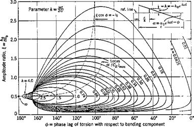
By calculating the energy input from the airstream the stability of more complicated motions can be determined. The bending-torsion case, in an incompressible fluid, has been calculated by J. H. Greidanus5 43 whose result, with a slight addition, is reproduced in Fig. 5.2. The airfoil is assumed rigid. The vertical translation, called bending, is denoted by h and is positive downward. The rotation about the 1/4-chord point, called torsion, is denoted by a and is positive nose up. The fluid is assumed nonviscous and incompressible, and the linearized two-dimensional aerodynamic theory is used. Let Ё be the mean work per unit time done by the aerodynamic force per unit span in a harmonic oscillation of

Подпись: Fig. 5.1. Vector diagram of lift in vertical translation oscillation. A vector drawn from the origin to an appropriate point on the curve gives a complex number (real part, abscissa; imaginary part, ordinate) that is the value of LjL0 given by the linearized theory. Curve given by von Karman and Sears, Ref. 13.21. (Courtesy of the Institute of the Aeronautical Sciences.)
Подпись: frequency со (radians per second). The expressions given by Greidanus are

Ё = {:77pc4co3a02Cs

CE =Mk)P – Шк) sin ф + ffk) cos ф]І ~ і

where

I = dimensionless ratio /г0/(«ос) h = h0eiu>t

Here ф represents the phase lag of the torsion behind the bending. The functions /1; /2, /3 are functions of the reduced frequency к derived from the theory of oscillating airfoils which will be presented in Chapter 13. All critical oscillations are given by the equation

CE = 0 (9)

The solutions of this equation are plotted in Fig. 5.2. Inside each loop, CE is positive and the oscillation is unstable.

. THE EXTRACTION OF ENERGY FROM AIRSTREAM

Fig. 5.2. Energy coefficient in bending-lorsion oscillations according to Greidanus, Ref. 5.43. (Courtesy of the Institute of the Aeronautical Sciences.)

For U -»• 00, к 0, the entire half-strip | > 0, 0 < < я – becomes

unstable, к -» 0 also when со -»• 0 if V remain finite, then Ё tends to zero as fast as со3.

For U -> 0, к -> oo, only one limiting point reaches the critical con­dition of neutral stability. This is

І = і, Ф = tt

which implies that the wing is oscillating about the 3/4-chord point, because the downward displacement at a point located at a distance xc behind the 1/4-chord point is

z = h0eM + ос0хсе1<-ы~ф) (10)

which vanishes when x = f and ф = ъ. When £ = 1/2, the 3/4-chord point is stationary. Thus, in the absence of structural damping, a wing reaches the critical flutter condition at zero airspeed if the oscillation node is

located at the 3/4-chord point. In practice, structural damping always exists and flutter in this case does not occur; but Biot and Arnold5-42 have shown that, if the nodal line of oscillation of a wing is located close to the 3/4-chord line, flutter at low airspeed is likely to occur.

For intermediate values of U, к is finite. The loops of instability become smaller as к increases.

From Eq. 10, the location x where the amplitude of |z| becomes a minimum can be calculated. The result is

X = — I COS ф (11)

It coincides with the 3/4-chord point if £ cos <f> = —1/2, a relation repre­sented by a dotted curve in Fig. 5.2, which appears to pass right through the dangerous area. This indicates again that flutter is liable to occur if the node of oscillation is located near the 3/4-chord point.

It is particularly interesting to consider the possibility of one-degree-of- freedom flutter. A purely translation motion corresponds to a0 = 0 or £ = oo, which by Fig. 5.2 is stable for all к > 0, confirming a result obtained previously. A purely rotational motion exists if there is a node. From Eq. 10 we see that z vanishes at all time t if and only if

h0eiml + «0схет~ф) = 0 (12)

Eq. 12 is satisfied by pitching about the 1/4-chord point, corresponding to x = h0 = 0, which, for к > 0, is seen from Fig. 5.2 to be stable for all values of ф between 0 and tt. For nonvanishing x, Eq. 12 is satisfied if

(a) ф = п, x = I (13)

(b) ф = 0, x = — I

Case a is the oscillation about the 3/4-chord point discussed above. Case b leads to flutter, according to Fig. 5.2, only if к < 0.0435, and for axis of rotation located forward of the 1/4-chord point, yet not too far forward of the airfoil leading edge. This torsional flutter was first found by Glauert in 1929. It is discussed in detail by Smilg.5-50 Recently, several types of single-degree-of-freedom flutter involving control surfaces at both subsonic and supersonic speeds have been found,5.45-5.49 ац requiring the fulfillment of certain special conditions on the rotational-axis locations, the reduced frequency, and the mass moment of inertia. Pure – bending flutter is possible for a cantilever swept wing if it is heavy enough relative to the surrounding air and has a sufficiently large sweep angle.5-46

The preceding analysis is purely kinematical. It does not tell how the phase shift ф and the reduced frequency к will vary with the flow speed U for a given structure. The latter information must be obtained from a consideration of the balance of the inertia and elastic forces witH the
aerodynamic forces. Thus a dynamic analysis is necessary to determine which point on a figure such as Fig. 5.2 corresponds to a given structure at a given airspeed U. Such a dynamic analysis is the subject matter of the next two chapters.

STIFFNESS CRITERIA

According to an analysis of the data on several airplanes in which wing flutter has been observed, and on others that showed no tendency to flutter, Kiissner found in 1929 that, for airplane wings with mass- unbalanced ailerons, of the type of construction prevalent at that time, wing-aileron flutter occurs when the reduced frequency is lower than the following critical value:

0)C

^cr = 2t/ = 0.9 ±0.12 (1)

where U = the mean speed of flow, feet per second; со = the fundamental frequency of the wing in torsional oscillation in still air, radians per second; and c — the chord length of the vibrating portion of the wing, feet.

Подпись: U„ Подпись: coc 2k,.r Подпись: (2)

For safety against flutter, the reduced frequency should be higher than k„. In other words, the design speed of the airplane must be lower than

This is Kiissner’s well-known formula. The frequency со may be deter­mined by ground vibration experiments in still air or computed by a

theoretical analysis. It increases with increasing stiffness of the structure. Therefore, the critical speed can be raised by increasing the wing stiffness. From this point of view we see that when the lower limit of Uct is pre­scribed (e. g., the maximum speed of flight) a minimum value of w, and hence a minimum value of the torsional rigidity is also prescribed.

STIFFNESS CRITERIA
Подпись: (5)
Подпись: where

Thus a stiffness criterion can be specified for the purpose of flutter prevention. If we return to the parameters used at the beginning of the last section, Kiissner’s formula can be expressed in the form

> const №

If the inequality sign is satisfied, flutter will not occur.

The stiffness criterion, regarded as a specification of the wing stiffness with regard to flutter prevention, is convenient for a designer.

Such stiffness criteria arise also in the consideration of steady-state instabilities (cf. Chapters 3 and 4). Most types of aeroelastic instabilities can be avoided by sufficiently high structural stiffness. For the safety against each type of instability, inequalities of the following form are to be satisfied.

Ко

p U[14]sc2

1.

Подпись: (4)
Подпись: > const

Torsional-stiffness criterion:

Подпись: torque applied at effective tip angle of twist at effective tipКо — torsional stiffness of the wing =

Kh — flexural stiffness of the wing

maximum bending moment x semispan
linear deflection of tip

s = semispan

c — mean chord of the wing

The constants in the above equations depend on many parameters, such as the type of structural construction, the locations of the elastic axis and the center of mass of the wing, the moment of inertia of the sections, the amount of mass balancing. The final form of the stiffness criteria can be obtained for a particular type of structure only after consideration has been given to all the possible instabilities.

As an example, let us quote the case of flutter of a thin-walled circular cylindrical shell of uniform thickness in a supersonic flow along the axis of the cylinder. Such a shell is used often in large liquid-fueled rockets, particularly at the interstage area. Experiments in a wind tunnel revealed that such a shell may have several types of oscillations: the small amplitude random oscillations, the sinusoidal flutter oscillations, and the sinusoidal flutter motion whose amplitude varies periodically over the circumference of the cylinder and moves as a traveling wave. Tested at a Mach number of 2.49, the amplitude of the last two types of oscillations would suddenly rise at the critical condition

STIFFNESS CRITERIA(6)

in which q = ipU2, is the dynamic pressure of the main flow, R is the radius of the middle surface of the circular cylinder, h is the thickness of the shell wall, E is the Young’s modulus of the shell material, and /3 = V M2 — 1 is a function of the Mach number. In a limited range of experiments this critical condition is independent of the internal pressure as long as it is positive. The critical condition (6) may be regarded as a stiffness cri­terion. Details of the experiments are given in the author’s paper, Ref.

NONDIMENSIONAL PARAMETERS

Two mechanical systems are said to be similar when they are similar in geometry and in the distribution of mass and elasticity. In flutter analysis, let us consider two similar systems and assume that the motion is dependent on the following fundamental variables:

Symbol

Significance

Physical Dimensions

/

Typical linear dimension

L

V

Air speed

LT-1

P

Air density

ML-3

a

Typical density of structural material

ML-3

К

Typical torsional stiffness constant (ft-lb per rad) ML2T~2

These five variables can be combined into two independent nondimensional parameters, such as

a aPU2

Any nondimensional quantity relating to the motion can be expressed as a function of these parameters. Thus if, in a free oscillation, the deflection at a point is described by an expression e~et cos cot, the damping factor e, of dimension (Г-1), can be combined with U and /

NONDIMENSIONAL PARAMETERS

to form a nondimensional parameter el/U, and hence satisfies a functional relation:

where F is some function of the arguments (1). Therefore, a sufficient condition for two similar systems to have the same value of el/U (in particular, to have є = 0, which corresponds to the critical flutter con­dition) is that they have the same values of the parameters pja and K/(aPU2).

NONDIMENSIONAL PARAMETERS Подпись: (3)

The frequency of oscillation со (radians per second), with dimension (7’~1), can be expressed nondimensionally in the parameter

NONDIMENSIONAL PARAMETERS

which is called the reduced frequency or Strouhal number (§ 1.5). Hence, there exists a functional relation

Combining Eqs. 4 and 2, we see that two similar systems having the same values of pja and Kj{aPU2) flutter at the same reduced frequency.

Since all derived concepts relating to the motion can be expressed in functional relations as above, it is clear that the equality of the values of the parameters pja and K/(alzU2) is sufficient to guarantee dynamic similarity of the two systems.

In a more careful consideration, the energy dissipation of the structure and the viscosity and compressibility of the fluid must be added to the list of fundamental variables. These can be incorporated non-dimen – sionally as the material damping coefficient g, the Reynolds number R, and the Mach number M. Dynamic similarity requires the equality offg, R, and M in addition to parameters in expression (1). In general, g is important in control-surface flutter, R is important in stall flutter, and M is important in high-speed flight; otherwise their effects are small.

The Strouhal number, or the reduced frequency k, is the most natural parameter in the consideration of unsteady aerodynamic forces. When­ever convenient, the parameters pja and k, instead of those in (1), may be taken as the fundamental parameters for dynamic similarity of flutter models. It should be noted that, if the Strouhal number is calculated for the fundamental oscillation frequency of the structure, it can be identified with the second parameter in (1): The factor VKjaP, of dimension Г-1,
represents a frequency of oscillation. Hence, the parameter K/(aPU2) can be identified with the square of the Strouhal number.

The Strouhal number, or reduced frequency, characterizes the variation of the flow with time. Its inverse, I//(a>/), is called the reduced speed. An interesting interpretation of the reduced frequency is given by von Karman as follows. Consider that a disturbance occurs at a point on a body and oscillates together with the body. The fluid influenced by the disturbance moves downstream with a mean velocity U. Let the fre­quency of oscillation of the body and the disturbance be со. Then the. spacing, or “wave length” of the disturbance, is l-nUju). Therefore, the ratio

2-nU 1(0 со 2irU

which is proportional to the reduced frequency shows that к represents a ratio of the characteristic length / of the body to the wave length of the disturbance. In other words, the reduced frequency characterizes the way a disturbance is felt at other points of the body. Since every point of an oscillating body disturbs the flow, one may say that the reduced frequency characterizes the mutual influence between the motion at various points of the body.

BIBLIOGRAPHY

FLUTTER PHENOMENON

5.1 THE PHENOMENON OF FLUTTER

A type of oscillation of airplane wings and control surfaces has been observed since the early days of flight. To describe the physical phen­omenon, let us consider a cantilever wing, without sweepback and with­out aileron, mounted in a wind tunnel at a small angle of attack and with a rigid support at the root. When there is no flow in the wind tunnel, and the model is disturbed, say, by a poke with a rod, oscillation sets in, which is damped gradually. When the speed of flow in the wind tunnel gradually increases, the rate of damping of the oscillation of the disturbed airfoil first increases. With further increase of the speed of flow, however, a point is reached at which the damping rapidly decreases. At the critical flutter speed, an oscillation can just maintain itself with steady amplitude. At speeds of flow somewhat above the critical, a small accidental disturbance of the airfoil can serve as a trigger to initiate an oscillation of great violence. In such circumstances the airfoil suffers from oscillatory instability and is said to flutter.*

Experiments on wing flutter show that the oscillation is self-sustained;

i. e., no external oscillator or forcing agency is required. The motion can maintain itself or grow for a range of wind speed which is more or less wide according to the design of the wing and the conditions of the test. For a simple cantilever wing, flutter occurs at any wind speed above the critical. In other instances, for example, in flutter involving aileron motion, there may be one or more ranges of speed for which flutter occurs, and these are bounded at both ends by critical speeds at which an oscilla­tion of constant amplitude can just maintain itself.

The oscillatory motion of a fluttering cantilever wing has both flexural and torsional components. A rigid airfoil so constrained as to have only the flexural degree of freedom does not flutter. A rigid airfoil with only the torsional degree of freedom can flutter only if the angle of attack is at or near the stalling angle (“stall flutter,” Chapter 9), or for some special mass distributions and elastic-axis locations. In ordinary circumstances, oscillations of a control surface (aileron, flap, etc.), in a single degree of

* In the following text, the terms flutter speed and flutter frequency refer to the critical flutter speed and the frequency at the critical condition.

160

freedom, are also damped at all speeds unless a flow separation is involved. Let us restrict the term ‘‘’flutter” to the oscillatory instability in a potential flow, in which neither separation nor strong shocks are involved[13] Then, in general, the coupling of several degrees of freedom is an essential feature for flutter. The steady oscillation that occurs at the critical speed is harmonic. Experiments on cantilever wings show that the flexural movements at all points across the span are approximately in phase with one another, and likewise the torsional movements are all approximately in phase, f but the flexure is considerably out of phase from the torsional movement. It will be seen later that mainly it is this phase difference that is responsible for the occurrence of flutter.

The importance of phase shift between motions in various degrees of freedom suggests at once the importance of the number of degrees of freedom on flutter. An airplane wing, as an elastic body, has infinitely many degrees of freedom. But owing to its particular construction, its elastic deformation in any chordwise section can usually be described with sufficient accuracy by two quantities: the deflection at a reference point, and the angle of rotation about that point, i. e., the flexural and the torsional deformations, respectively. Similarly, for a control surface, such as a flap or an aileron, its freedom to turn about the hinge line is so much more important than its elastic deformation, that ordinarily it is possible to describe the deflection of a control surface simply by the angle of rotation about its hinge line. In general, then, it is sufficient to con­sider three variables in wing flutter: the flexure, the torsion, and the control-surface rotation. A flutter mode consisting of all three elements is called a ternary flutter. In special cases, however, two of the variables predominate, and the corresponding flutter modes are called binary flutter modes. Similar consideration applies to airplane tail surfaces. In fact, most airplanes can be replaced by a substitutional system of simple beams, so that the elastic deformation can be described by the deflection and torsion of the elastic axes of the substitutional beams, in addition to the rotation of control surfaces about their hinge lines.

These degrees of freedom, together with the freedom of the airplane to move as a rigid body, offer a large number of possible combinations of binary, ternary, and higher modes of flutter. Since it is not clear which of these modes correspond to the actual critical speeds, it is necessary

either to resort to experiments or, in a theoretical approach, to analyze all cases. This is why a successful flutter analysis depends so much on the analyst’s experience. He must be able to choose, among all possible modes, those that are likely to be critical for a given structure.

Since flutter analysis is a rather extensive subject, we shall divide our discussions into three chapters. In the present chapter only some general considerations based on dimensional arguments will be given. The role of the elastic stiffness and the mass balancing in flutter prevention are explained on the empirical basis. The origin of flutter from the aero­dynamic point of view is then considered in § 5.4. It will be shown that flutter occurs because the speed of flow affects the amplitude ratios and phase shifts between motion in various degrees of freedom in such a way that energy can be absorbed by the airfoil from the airstream passing by. Some remarks on the experimental approach to the flutter problem are given in § 5.6, and the dynamic similarity rules are discussed in § 5.7. A brief historical review of the earlier developments is included in § 5.8. The details of the dynamical process, however, are left for the next two chapters.