Category An Introduction to THE THEORY OF. AEROELASTICITY

METHODS OF DETERMINING THE CRITICAL SPEEDS

The methods discussed in the last two sections can be extended to systems having any finite number (say ri) of degrees of freedom. Several different points of view may be used to determine the critical flutter speeds. In the forced-oscillation method (§ 6.9), we may proceed to write down the equations of motion, with an (undetermined) external excitating force acting in one of the degrees of freedom (say the first equation), and with no excitation term in the remaining (n — 1) equations. The amplitude and phase angle of one of the remaining degrees of freedom (say the nth) may be arbitrarily assumed. For a given speed of flow and given fre­quency, these (n — 1) homogeneous equations can be used to determine the amplitude and phase angle of various degrees of freedom in proportion to the nth, and the first equation can then be used to determine the magnitude and phase of the exciting force required to act in the first degree of freedom to produce the assumed motion. A variation in the speed of flow and the oscillation frequency will produce a corresponding change in the required exciting forces. By repeating the calculations for different combinations of speed and frequency, the trend of changes in the exciting force can be determined, and the speed and frequency at which the exciting force vanishes can be obtained. These are the flutter speed

* Ref. 6.8 also gives examples to show that the stability of a wing cannot be determined by measuring the work done by an exciting force in a steady forced oscillation. The reason is very simple: The amplitude and phase relationship between various compon­ents of motion vary with the frequency and the point of application of the exciting force. In particular, the amplitude and phase relationship in forced oscillation are in general different from those in a free oscillation. From § 5.4 it is clear that such variations will cause an important change in the energy exchange between the wing and the airstream. Frazer shows that in certain cases it is possible to provide a mechanism which extracts energy from a wing, yet causing an otherwise stable wing to oscillate sinusoidally.

and frequency. • This method has been applied by Duncan6-6’67 and Myklestad6,17 to systems having many degrees of freedom.

It is also possible to study the free oscillations following an initial disturbance and define flutter as a condition at which an oscillation of nondecreasing amplitude is obtained. A method of iteration for such calculation has been used by Goland and Luke.6-11 When the existence of flutter is presupposed, as in § 6.10, the airspeed and oscillation frequency are sought. The similarity of this formulation to the classical vibration problem of a mechanical system in still air indicates that flutter is a complex eigenvalue problem.* Besides Theodor – sen’s method, this problem may be solved by matrix methods as given by Duncan, Frazer, and Collar,6-5 or by the method of iteration, as expounded by Jordan,614 Kussner,5-28 Wielandt,11-24 Greidanus, and van de Vooren.6-12 A method proposed by R. A. Frazer610 regards the flutter determinant as defining an eigenvalue problem involving two real-valued eigenvalues, one related to the reduced frequency and the other to the stiffness of the structure.

The most straightforward method is to write the flutter equation as a matrix equation, form the characteristic equation, and solve the complex eigenvalues. The quickest way, however, is to use an analog computer. For analog approach we refer to the book by McNeal.6-28 The aero – elastic system is simulated by an electric network. An example of such an analog sets up the following correspondence:

Capacitors—concentrated or lumped inertia properties Inductors—lumped flexibility properties Transformers—geometric properties Voltage—velocities Current—forces

Such an electric analog can be regarded as a model of aircraft whose properties can be altered easily. A parametric study of the aircraft can be done with great rapidity. A particular advantage of the electric analog method is that tuned pulses may be used to separate two or more nearly unstable modes of motion.

Whereas the most convenient form of aerodynamic information used in the influence-functions formulation is the frequency response, in the analog method indicial responses are used: e. g., the lift due to a sudden change of angle of attack, the moment due to a sudden aileron deflection, etc. They can be approximated by a finite sum of exponential functions. The electric analog for the aerodynamic system can then be recognized

* Further references regarding the mathematical problem of complex eigenvalues can be found in Chapter 11.

relatively easily by an examination of the Laplace transforms of the indicial responses.

In all the methods mentioned above, one tries to find the actual airspeed at which flutter may occur, but often this is more than necessary from the point of view of airplane design. In fact, an airplane may be regarded as nonexistent for airspeeds exceeding the design speeds. The immediate question regarding the safety against flutter is this: Will the airplane flutter within the “design envelope” of Mach number and altitude? This question has a different content from the question of finding the flutter speeds in terms of miles per hour. We are concerned only with the sta­bility of the aeroelastic system in a given speed range. Mathematically, we are dealing with the problem of the existence of an eigenvalue within a specified range, instead of finding out its numerical value. Certain methods applicable to this problem will be discussed in § 10.6.

SOLUTION OF THE FLUTTER DETERMINANT

SOLUTION OF THE FLUTTER DETERMINANT

The method used in § 6.9, of finding the flutter speed by plotting the solutions of the real and imaginary parts of the flutter determinant, is often referred to in U. S. literature as Theodorsen’s method. This method can be used to solve the determinanta-l equation 21 of § 6.10. Let

Only the diagonal terms A, E, and / in Eq. 21 of § 6.10 involve X. For a given value of k, all the terms of the determinant are known (complex numbers). If the real and imaginary parts are separated, it can then be written as two cubic equations with real coefficients involving X as an unknown. The roots of these equations, when plotted against l/к, yield two curves, the intersection of which determines the reduced frequency к and frequency ratio cojco at flutter. The critical speed and frequency are then given by Eqs. 28 of § 6.9.

For a compressible fluid, the available aerodynamic data are such that it is necessary to assume both a Mach number and a reduced frequency in order to obtain numerical values of the determinant. Let the assumed value of the Mach number be M. For this M, let the flutter-speed calculated by the procedure outlined above be U, which corresponds to a Mach number M’. Varying M will lead to other values of M’. The true solution is obtained when M = M’. Hence, a process of trial and error is necessary. In § 10.6, a process based on Nyquist’s criterion of stability will be described, which makes it possible to state whether flutter will or will not occur at a given Mach number. Although the Nyquist approach does not give the flutter speed directly, it does make a definite statement about the aeroelastiic stability.

Example 1. Consider the torsion-bending flutter of the following two- dimensional section (of a suspension bridge):

b == 30 ft, r.? = 0.6222

m == 269 slugs per foot, (2)

coh2 == 0.775, m«2 = 2.41

The elastic axis lies on the mid-chord line, and the mass distribution is symmetrical. Hence,

ah = 0, xx = 0 (3)

In this case

fi = = 40

irpfe2 (4)

p = 0.002378 slug per cubic foot Consider first gh = gx = 0. Then

A = 40(1 – 0.3216X) + Lh В — La 0.5Lh

D = 0.5 – 0.5Lh K }

E = 24.8928(1 – X) – 0.25 + Mx – 0.5Lx + 0.25Lh Assuming 1 /к = 2.00, we find from the tables of Lh, Lx, etc. (Smilg and

Wasserman6’20, A. F.Tech. Report 4798; or p. 409, Rosenberg and Scan – lan,6-19):

Lh = 0.3972 – 2.3916/, La = – 4.8860 – 3.1860/

Ma = 0.3750 – 2.0000/ (6^

Hence,

A = 40.4049 – 2.3916/ – 12.8665X В = – 5.0846 – 1.9902/

D = 0.3014 + 1.1958/ (7)

E = 27.5601 – 1.0049/ – 24.8928X

The determinant

A

D E

becomes 320.283X2 + 74.463/X – 1360.393ЛГ – 99.836/ + 1110.312 = 0 (8)

Separating the real and imaginary parts, we get

1. Real Equation:

320.283X2 – 1360.393X+ 1110.312 = 0

The roots are

Подпись: (9)X= 1.1022 and X= 3.150 or _ __

VX= 1.0499 and Vx= 1.466

2. Imaginary Equation:

74.463X – 99.836 = 0

The root is _

X= 1.3777 or VX= 1.1738 (10)

By repeating the process for other assumed values of Ijk, a table of the roots Vx as a function l/к can be prepared (Table 6.2).

Table 6.2

1

Vx

к

From Real Eq.

From Imaginary Eq.

2

1.0499

1.1738

2.94

1.1097

1.2043

3.33

1.1420

1.2155

4.17

1.2241

1.2364

5.00

1.3236

1.2538

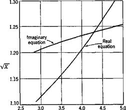
Figure 6.18 shows a plot of these roots vs. I/к. It is seen that the real and imaginary equations are both satisfied at the intersection of the curves:

1=4.31, Vx = 1.239 (11)

Hence, the corresponding critical flutter speed

U„ = — 162 ft per sec (12)

kVX

Only the smaller of the two roots VX of the real equation is listed in Table 6.2 and plotted in Fig. 6.18. The larger of the two roots of the

SOLUTION OF THE FLUTTER DETERMINANT

1№

Fig. 6.18. Example 1.

real equation forms a branch that does not intersect the curve for the imaginary equation. Hence, the above intersection is the only inter­section, and the critical flutter speed given by Eq. 12 is the only critical speed.

A different point of view is to consider the flutter determinant not as two real equations but as a single equation for the variable X. For each assumed value of k, this equation may be solved for X. Since the coefficients are complex functions of k, the roots are, in general, complex. But X, by definition (Eq. 1), must be real to have a physical meaning. Hence, we must find the particular value of к that renders the root X real. A plot of the real and complex parts of the roots X with к as a parameter
will indicate whether such a solution exists. If the fluid is compressible, the calculations must be repeated for different values of the Mach number M. The correct M’s are those for which the assumed values and the calculated values agree.

In practical application, it is more convenient to use a different variable than X. Note that со2 and g always appear together in the flutter deter­minant as (co»2(l + iga), etc. For small values of gh, ga, gp, we may write

1 + iga = 1 + igh + Kga. ~ gh) = (1 + igh)[ 1 – Г Kga ~ gh)] (13)

provided that gh(ga — gh) is negligibly small in comparison to gh. Hence, let

z=(5)’a + fe) (и.

Then the flutter determinant (Eq. 21 of § 6.10) can be written as a cubic equation in Z. For a given k, the (complex) roots Z can be found. If we plot the roots Z with their real parts (сох/ш)2 as the abscissa and the ratios of the imaginary part to the real part, gh, as the ordinate, we obtain a parametric curve showing the variation of Z with k. The correct values of к at which flutter is possible are those that correspond to the value of gh of the specific structure. The compressibility effects, if any, must be catered for as before.

Example 2. For the torsion-bending flutter of the numerical example 1 considered above, the determinantal equation for 1 jk = 2 is given by Eq. 8. It is a quadratic equation because only two degrees of freedom are allowed. Equation 8 is derived for g = 0. When g Ф 0, we must replace X by Z as defined by Eq. 14. Hence for 1 jk = 2, and assuming gn = g« = g> we have

320.283Z2 + 74.463/Z – 1360.393Z – 99.836/ + 1110.312 = 0 (15) This is of the form

aZ2 + bZ+c = 0 (16)

Подпись: and the roots are — b Vb2 — 4ac z(+) = Подпись: (17)Vb2 — Лас

2 a ’ ~J<-) 2a

Denoting the two roots of Eq. 15 by Z(+) and Z(_> as in Eqs. 17, we obtain Z(_) = 1.1051 – 0.0303/, Z(+) = 3.1424 – 0.1960/

By repeating this process for several other assumed values of Ijk, Table 6.3 is obtained.

1 Ik

z(_,

Im(Z,_,) 8 R1 (Z,_,)

zl+)

2

1.1051 -0.0303і

– 0.0274

3.1424 – 0.1960/

2.5

1.1842 – 0.0384г

– 0.0324

3.1249 – 0.2647/

2.94

1.2390 – 0.0426г

– 0.0344

3.1088 – 0.3344/

3.33

1.3134 -0.0411/

– 0.0313

3.0947 – 0.4059/

4.17

1.5023 – 0.0102/

– 0.0078

3.0723 – 0.5975/

5.00

1.7042 + 0.0745/

+ 0.0437

3.0911 – 0.8568/

Table 6.3

/1 = 40, b = 30,ft, со/ = 2.41

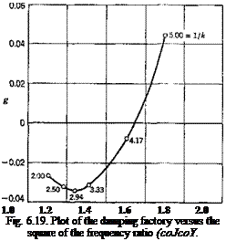
Clearly the imaginary part of Z<+) remains negative for all values of k. On the other hand, the sign of the imaginary part of Z(_t changes at certain value of k. According to the definition of Z (Eq. 14), the real part of Z is (wjco)2. The imaginary part is (wjw)2g. Hence,

Подпись:Im (Z) 8 ~ R1 (Z)

Подпись: 1.0 1.2 1.4 1.6 1.8 2.0 Fig. 6.19. Plot of the damping factory versus the square of the frequency ratio (coJcoY.

A plot of g vs. (wjco)2 with 1/k as a parameter is shown in Fig. 6.19. If

the value of g for the structure is zero, the critical condition is reached when

SOLUTION OF THE FLUTTER DETERMINANT– = 4.3]

SOLUTION OF THE FLUTTER DETERMINANT Подпись: 09)

The flutter speed is therefore

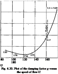
the function g can be plotted against U. The result is shown in Fig. 6.20.

This method was used by Smilg and Wasserman,6-20 and is sometimes known as “AMC” (Air Materiel Command) method. A tabular adaption for routine calculations has been published by Scanlan and Rosenbaum.619

Подпись:0.06

0.04

0.02 g

0

-0.02 -0.04

The values of to2 and g so obtained satisfy the flutter determinant, and determine a mode of flutter motion (i. e., the amplitude ratios and phase relations of h/b, a, /3, 6). Now suppose that, at a specific critical condi­tion, the value of g is increased by imposing certain dampers on the wing; would this stabilize the wing? The answer is uncertain, because by the change in g the phase relationship between various components of motion changes. A new energy balance is set up, and it is not obvious whether

this results in a stable or unstable motion. In other words, an increase in damping does not necessarily raise the flutter speed.

Although the numerical example given above shows an increase in Ucr by an increase of g, examples to the contrary can be constructed. Collar (see Chapter 8 of Ref. 3.20) has shown, for the case of pitching oscillations of a frictionally constrained airfoil, and Frazer6 8, for the case of wing bending-aileron rotation, that it is possible to adjust the wing mass distribution in such a way that the flutter speed decreases by imposing several types of damping: dry friction, viscous damping proportional to amplitude, and damping force proportional to the square of the amplitude.*

It may be pointed out that the destabilizing effect of damping is not entirely unfamiliar in aerodynamics. For example, the origin of turbu­lence in a flow lies in the viscosity of the fluid.

FLUTTER OF A TWO-DIMENSIONAL AIRFOIL

The example of the last section shows that for certain wing there exists an airspeed at which the wing response to a periodic forcing function tends to infinity at some particular frequency. At this combination of airspeed and frequency, the determinant of the coefficients of Eqs. 12 of § 6.9 vanishes and a nontrivial solution exists even when the forcing function vanishes: the aeroelastic system will oscillate harmonically without further excitation after an initial disturbance. The aeroelastic system is then said to be in the critical flutter condition.

In order to indicate the form of available aerodynamic tables and their application to flutter calculations, we shall consider in this section the critical flutter condition of a two-dimensional airfoil with an aileron and a control tab. Extensions to three-dimensional wings, tail surfaces, and other structures will be made in the next chapter.

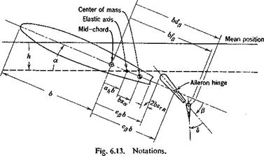
The Airfoil. Let us consider a two-dimensional airfoil of unit length in the spanwise direction, having four degrees of freedom h, a, /3, and 5, as shown schematically in Fig. 6.13, where

h = bending deflection of the elastic axis, positive downward, feet

a = pitching about the elastic axis, relative to the direction of flow, positive nose up, radians

/3 = angular deflection of aileron about aileron hinge, relative to wing chord, positive for aileron trailing edge down, radians

d = angular deflection of tab relative to aileron, positive trailing edge down, radians

We assume that h, a, /3, and <5 are infinitesimal, so that the flow remains potential and unseparated, and the linearization of the aerodynamic equations is justifiable.

FLUTTER OF A TWO-DIMENSIONAL AIRFOIL

The notations are shown in the figure. Note that the semichord is denoted by b. Other dimensions are referred nondimensionally to the semichord. Distances are measured with the mid-chord point as origin.

Thus,

cpb — distance between mid-chord and aileron hinge, positive if aileron hinge is aft of mid-chord

epb = distance between mid-chord and aileron leading edge, positive if aileron leading edge is aft of mid-chord

ahb = distance between elastic axis and mid-chord, positive if elastic axis is aft of mid-chord

Similarly, the dimensions dpb, fpb, xab, etc., can be identified.

Elastic Restraints. The displacements of the airfoil are restrained by elastic springs. A linear spring located at the elastic axis restrains the bending h. A torsional spring located at the same axis restrains the pitching a. The aileron rotation is restrained by a torsional spring at the aileron hinge line, and the tab by a spring at its own hinge. The spring constants will be denoted by Kh, Ka, Kp, and Ks. The elastic force due to a displacement h is — hKh, acting at the elastic axis, and in the direction opposing h. The moment about the elastic axis due to a is — a. Ka. Similarly, the moments about the aileron and tab hinges are — flKp and — 8Кб, respectively.

It is desirable to express the spring constants in terms of uncoupled natural frequencies as in § 6.8 (Eq. 6), and write

Kh = m/, Ka = /«соД Kfj = 1ршр K6 = Ком2 (1)

where m is the mass per unit span of the wing-aileron-tab combination, la is the moment of inertia per unit span of the wing-aileron-tab about the elastic axis, Ip is the aileron-tab moment of inertia about the aileron hinge, and К is the tab moment of inertia about the tab hinge. The frequencies coh, co„, cop, co<s are the uncoupled frequencies in radians per second, obtainable approximately by experiments, if necessary.

Structural Damping. The small structural damping of metal aircraft may be approximated by a force that opposes the motion and is in phase with the velocity. For simplicity of analysis, and also from lack of more accurate knowledge, we shall assume that the magnitude of the damping force is proportional to the elastic restoring force (cf. § 11.4). Since the motion of the airfoil is harmonic at the critical flutter condition, the condition is the same as in § 6.9, and the effect of the structural damping can be accounted for simply by replacing the terms hKh, a. Ka, etc., with terms hKh( 1 + igh), y. Ka( + iga), etc. The constants gh, ga, gp, gd are the damping coefficients.*

* Measurement by Fearnow on a full-scale airplane wing (C-46D) shows that g depends on the amplitude of motion and varies from 0.002 at an amplitude of vibration of 0.05 in. to approximately 0.012 at an amplitude of ± 5 in. (at wing tips). See Ref. ILL

Aerodynamic Forces.* The theory of oscillating airfoils, to be presented in Chapters 12 through 15, gives the necessary information about the aerodynamic forces acting on a fluttering wing. The theory is based on thin airfoils oscillating at infinitesimal amplitudes. At the flutter con­dition, we shall assume that

= ~ еш, a = а0еі(ш(+в‘), /3 = /30еІМ+Л), <5 = <50еі(ш(+в’) (2) where h0, a0, A)> йо are real numbers (small compared to 1), dv 62, 6S are the phase angles by which a, /3, <5 lead the wing bending displacement, and eo is the flutter frequency in radians per second. For a two-dimensional airfoil having these four degrees of freedom, in a flow of speed U, the aerodynamic forces are functions of the dimensionless numbers:

M = Mach number = U/c (3)

к = reduced frequency or Strouhal number = wb/U (4)

where c is the speed of sound propagation in the undisturbed flow. The aerodynamic expressions are simpler if the motion, as well as the forces and moments, are referred to the aerodynamic center. For a subsonic flow the aerodynamic center is located at the 1/t-chord point aft of the wing leading edge. Hence, let us introduce the following nondimensional generalized displacements:

(5)

* In most British papers, the so-called classical derivative theory is used. Following Frazer and Duncan, the aerodynamic forces are assumed to be linear functions of the generalized displacements, velocities, and accelerations. For example, let s denote the linear downward displacement of the leading edge and a the increase in angle of attack from a mean position at a local chordwise section of the wing. Then it is assumed that the corresponding local aerodynamic lift L (positive upward) and the moment M (referred to the leading edge, positive nose up), per unit span, may be expressed in the form

LI(pV2c) = (Іф + Іф + Іф)/с + (k a + lid + lx«)

-M/(pUV) = (тф + тф + тф)Іс + (гпф. + тф + тх а)

where с is the local chord and a superposed dot denotes differentiation with respect to a dimensionless time r = Ut/c. The coefficients 4, 4, etc., are assumed to be inde­pendent of the reduced frequency, aspect ratio, planform, and modes of motion of the wing. In an incompressible fluid, a set of “mean experimental values” given by J. Williams (Ref. 6.24) is the following:

/і = 1.6,

k

= 1.6,

lx = 1.8,

/2 = o

= 0.4,

mx

= 0.7,

ma — 0.45,

О

і!

м

5

h = *74,

k

= m-i = TJ-/8,

mx — 9jt/128

where

Wc/4 = fi-b(i + ah) a

= bending displacement of the V4-chord point (6)

a = pitching displacement about the V4-chord point

Подпись: Fig. 6.14. Resolution of aileron motion.

Similarly, for an aileron with aerodynamic balance, it is convenient to resolve the aileron motion about its hinge line into two components, a rotation about the aileron leading edge and a vertical translation of the

aileron in the direction perpendicular to the wing chord (positive down­ward) (Fig. 6.14). The rotation about the aileron leading edge is/9. The vertical translation must have an amplitude

2 = – (cff – efibp (7)

so that the resultant of the rotation about the leading edge j} and the translation z may leave the aileron hinge line fixed with respect to the wing chord.

The tab rotation can be similarly treated. But for simplicity let us assume the tab to be hinged at its leading edge.

Thus in addition to qx, q2 defined by Eqs. 5, we have the following nondimensional displacements:

?з = /9, ?4 = Ф, Чъ = <5 (8)

These five displacements are illustrated in Fig. 6.15.

When h, a, /9, z, б all vary sinusoidally as given in Eqs. 2, the aero­dynamic lift per unit span, Lc/i, acting at the 1/4-chord point,* positive upward in the usual sense, can be written as:

Подпись: 7Tpb3OJ2і Lh + + £ Lz + j

* In supersonic flow, it is more convenient to resolve lift and moment about the mid-chord point. Note here that a negative sign is attached to the right-hand side of Eqs. 9,10 and 12. The lift forces Lc/i and Рл_ are defined as positive when their vector directions are upward, as in the usual sign convention for a lift force. But, in Smilg and Wasserman’s paper,6-20 from which extensive tables for Lh, Lx, etc., are obtained, the opposite sign conventions are used. The negatives signs are chosen for Eqs. 9, 10 and 12 so that the existing tables for Lh, Lx, etc., can be used.

where Lh, La, etc., are nondimensional coefficients. To shorten the writing, let us write the sum in the bracket [ ] as ^jqtL(. Thus

Lc,4 = – ттрЬ3тг 2ЯіЦ (10)

In a similar way, the aerodynamic moment per unit span about the 74- chord point, Мец, positive in the nose-up sense, can be written as

Analogously, the force per unit span on the aileron, Ple positive up, is

pi. e. = – ггрЬЧ)2 2Чірі (12)

The moment per unit span about the leading edge of the aileron, 7] e positive trailing edge down, is

Тіл. = V>4«2 2<I<Ti 03)

The aerodynamic coefficients L(, M(, P{, T(, (2 = 1, 2, • • •, 5) are com­pletely’defined by the above equations. Linearity is assumed in order
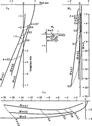
that these equations may be valid. In the theoretical derivation of these coefficients (Chapters 13 and 14), the fluid is assumed to be nonviscous so that Mt, etc., are functions of the Mach number and the reduced frequency. For a real fluid, they are also functions of the Reynolds number. Figure 6.16 show the theoretical curves of the complex numbers

FLUTTER OF A TWO-DIMENSIONAL AIRFOIL

Fig. 6.16. Theoretical values of the complex numbers Lh, Lx, Mh, and Мл for various Mach numbers and reduced frequencies. A vector drawn from the origin to an appropriate point on a curve gives a complex number (real part, abscissa; imaginary part, ordinate) which is the value of Lh, etc., given by the linearized theory. Note the difference in scales between Lh, Mh and La, Ma.

Lh, Lx, Mh, Mx at several Mach numbers with the reduced frequency к as a parameter.

The source references from which the aerodynamic coefficients Ц, Mit etc., can be obtained are reviewed in §§ 13.6 and 14.7. Throughout the literature various notations and forms of the coefficients have been used. A comparison between the notations of different authors is given in Tables 13.1 and 14.2. The notations used in Eqs. 10 through 13 are introduced in Army Air Force Technical Report 4798, (1942), by Smilg and Wasserman.

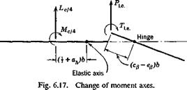
The aerodynamic forces and moments about the elastic axis of the wing and the hinge line of the aileron can be easily computed from Lcli, Мец, Ple, and Tl e. Let the force and moment at the elastic axis be Lb a and Me a,, respectively, and the moment about the aileron hinge line rhinge. From Fig. 6.17 is it clear that

Me.&. — Мсц + Lct4 (I + ah)b

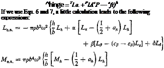
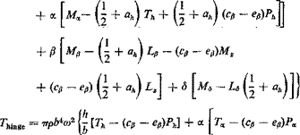
Подпись: ^hinge = Tl.e. + PlAcP — efi)b If we use Eqs. 6 and 7, a little calculation leads to the following expressions:
Подпись: (15)
FLUTTER OF A TWO-DIMENSIONAL AIRFOIL

(14)

+ m – – ev)(pe + г,) +

— S[Ts — Рв(ср — Сд)]|

The Equations of Motion. By a summation of the inertia, elastic, damping, and aerodynamic forces, we obtain the equations of motion in a manner described in § 6.8. In the following discussions, we shall assume that the tab is geared to the aileron so that

d = nfi (16)

where n is a proportional constant. The rigidity of the tab constraint about its hinge is considered as infinite. The equation of motion for the tab can therefore be omitted.

FLUTTER OF A TWO-DIMENSIONAL AIRFOIL

Denoting the time derivatives by dots, we obtain the following equations of motion:

mh + Sx& + (Sp + nS6)fi + (1 + igh)Khh + Lea = 0 Sji + ІЛ + [(ер – ah)bSp + Ip + nh + b(dfi – ah)nSefi

+ (1 + ig*)Kxx – Me. a. = 0 (17)

Sph + [Ip + Ь{сц — ah)Sf,]a + [f + nh + b(dp – Ср)п8в]$

+ (1 + igpWpfi — Thinge = 0

where

m = mass of wing-aileron-tab (per unit span)

Sx — static moment of wing-aileron-tab about wing elastic axis (per unit span)

Sp = aileron-tab static moment (per unit span) about aileron hinge line Sp — tab static moment (per unit span) about tab hinge line

Ix = mass moment of inertia of wing-aileron-tab about wing elastic axis

Ip — mass moment of inertia of aileron-tab about aileron hinge line Is = mass moment of inertia of tab about tab hinge line

Let us assume that flutter exists. The wing thus can oscillate harmonic­ally as given by Eqs. 2 so that

h — — aPh, a = — ю2а, Д = — a>2/3 (18)

Substituting Eqs.. 15 and 18 into 17, and dividing the first equation by ттрЬ3а>2 and the other two by ттрЬ*оз2, we obtain

A – + Ву – f* Cft — 0 b

Подпись: (19)h

D – + Ea. + Fft = 0 b

Подпись:where

A = (x

В — i-ixa – j – 1-j – L}L(h “г ^/:)

С = /л{хр – f- nxg) + Lp — Lz(cfj — ep) + nLe

(1 + ig*)

FLUTTER OF A TWO-DIMENSIONAL AIRFOIL Подпись: (20)

D — pxx + Mih — Lh{ + ah)

If flutter exists, h, a, /9 do not vanish identically. Such a nontrivial solution exists when and only when the determinant of coefficients in Eqs. 19 vanishes:

Подпись: (21)ABC D E F = 0 G H I

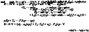
This characteristic equation involves the following real variables, U, со, к, p, coh, cox, wp, gh, gx, gp, and parameters defining the geometrical and mass distributions of the airfoil. Since Eq. 21 is an equation with complex coefficients, and since the real and imaginary parts of the deter­minant must vanish separately, it is actually equivalent to two real equa­tions for these real variables. It can be used to determine any two of these variables, while others must be specified. The choice of particular variables to be considered as the unknowns depends on the information desired and the expediency of calculation.

When Eq. 21 is satisfied. Eqs. 19 may be solved for the ratios A/6:a:/5, which are complex numbers showing both the amplitude ratios and phase relationship.

Application of the Two-Dimensional Analysis. Regarding the two – dimensional airfoil as a typjcal section of a three-dimensional wing, and adjusting the spring constants in such a way that the frequencies coh, cox, etc., coincide with the actual uncoupled free vibration frequencies of the wing, while the mass and geometric properties are taken as those of a typical section, one may expect that the critical flutter speed calculated for the two-dimensional case approximates that of the actual wing. This was shown to be true by Theodorsen and Garrick6-22 for wings without appreci­able sweep angle, without large concentrated mass, with more or less uniform distribution of structural properties across the span, with straight elastic and inertial axes, and with high chordwise rigidity. The location of the typical section is of some importance. Generally it is taken in the neighborhood of 0.7 span from the root, or at the mid-span of the aileron.

FORCED OSCILLATION DUE TO A PERIODIC EXCITATION

Consider the forced oscillation of a two-dimensional airfoil in a flow, under a harmonic exciting force. We shall have, then, the external force and moment per unit span

P = V*. Q = Q0eM (1)

where P0 and Q0 are complex constants (see § 1.8).

* The lift Цт) is defined as positive upward according to the usual sign convention in aerodynamics. The bending displacement h is positive downward. The forces on the right-hand side of Eqs. 3 are positive downward. Hence, the negative sign in front of L(r) in Eqs. 10.

Let us assume that the excitation has been operative for a long time and that the response of the system has reached a steady state.* The motion of the airfoil must be periodic and of the same period as the exciting force. Furthermore, because the system is linear, the response must be harmonic if the exciting force is. Hence, we may write

h = h0eiat, ol = а0еш (2)

where h0 and a,, are complex constants, the absolute values of which represent the amplitudes, and the arguments, the phase angles.

It is convenient to use the nondimensional time r. Then, since

Подпись:U

T~~bt

we may write

Р(Т) = РдЄІк Q(T) = Qg^

h(r) — h0eikr, а(т) = ctgetkT

where к is the reduced frequency

Подпись:к

When h(f) and а(т) are represented by Eqs. 4, the integrals involved in Eqs. 8 and 9 of § 6.8 can be evaluated. In order to avoid the mathematical difficulty of oscillatory divergence at the lower integration limit (— oo), we shall introduce a convergence factor e’T«, (e > 0), into the inte­grands, and pass to the limit є -> 0 through real, positive values after the integrals are evaluated. In other words, a divergent motion is considered first, but the degree of divergence is reduced to zero afterwards. The physical problem remains to be the finding of aerodynamic forces for harmonic oscillations. Let us write

lim ik f Ф(т – т0)еііт“+ет« dr0 = С(к)еікт (6)

e—й)+ J—• со

and therefore, on substituting Eq. 4,

– Tg) Ja’Oo) + ^ h"(T0) + Q — aAj a"(T0)j e"» dr0

= C(k) [ao + l – к hg + Q – ;7ca0j eikr (7)

* If the system is stable, the effect of the initial disturbance will die out as time increases. If the system is unstable, the effect of the initial disturbance will actually be magnified as time increases. Nevertheless, in both cases, the response of the system can be separated into two parts: (1) the steady-state response to the periodic force, and (2) the transient response to the initial disturbance. The first part is studied in this section.

FORCED OSCILLATION DUE TO A PERIODIC EXCITATION Подпись: Kfik) K0(ik) + Kfik) Подпись: (8)

The function C(k) is called Theodor sen’s function,* the exact expression of which, corresponding to Eq. 5 of § 6.7, is

Table 6.1 The Function C{k) = F – f iG, and Related Quantities

к

l/k

F

– G

-2 G/k

2F//c2

00

0.000

0.5000

0

0

o’

10.00

0.100

0.5006

0.0124

0.00248

0.010012

6.00

0.16667

0.5017

0.0206

0.00686

0.02787

4.00

0.250

0.5037

0.0305

0.01525

0.06296

3.00

0.33333

0.5063

0.0400

0.02667

0.1125

2.00

0.500

0.5129

0.0577

0.0577

0.2565

1.50

0.66667

0.5210

0.0736

0.0948

0.4631

1.20

0.83333

0.5300

0.0877

0.1462

0.7361

1.00

1.000

0.5394

0.1003

0.2006

1.0788

0.80

1.250

0.5541

0.1165

0.2912

1.7316

0.66

1.51516

0.5699

0.1308

0.3964

2.6166

0.60

1.66667

0.5788

0.1378

0.4593

3.2156

0.56

1.78572

0.5857

0Л428

0.5100

3.7353

0.50

2.000

0.5979

0.1507

0.6028

4.7832

0.44

2.27273

0.6130

0.1592

0.7236

6.3326

0.40

2.500

0.6250

0.1650

0.8250

7.8125

0.34

2.94118

0.6469

0.1738

1.022

11.192

0.30

3.33333

0.6650

0.1793

1.195

14.778

0.24

4.16667

0.6989

0.1862

1.552

24.267

0.20

5.000

0.7276

0.1886

1.886

36.380

0.16

6.250

0.7628

0.1876

2.345

59.592

0.12

8.33333

0.8063

0.1801

3.002

111.99

0.10

10.000

0.8320

0.1723

3.446

166.4

0.08

12.500

0.8604

0.1604

4.010

268.9

0.06

16.66667

0.8920

0.1426

4.753

495.6

0.05

20.000

0.9090

0.1305

5.220

727.2

0.04

25.000

0.9267

0.1160

5.800

1158.3

0.025

40.000

0.9545

0.0872

6.976

3054.4

0.01

100.000

0.9824

0.0482

9.640

19648

0

00

1.000

0

CO

CO

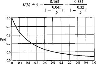
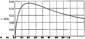
where H and К are the Hankel functions and the modified Bessel functions, respectively. The standard notations for the real and imaginary parts of C(k) are F and G, which are tabulated in Table 6.1,f and shown in Fig. 6.8.

* See §13.4.

t From Ref. 13.33. More extensive numerical tables of C(k) are given by Luke and Dengler, and Brower and Lassen, in Refs. 13.25 and 13.6, respectively.

Approximate expressions of C(k) corresponding to Eqs. 4 (R. T. Jones) and 4a (W. P. Jones) of § 6.7 are, respectively:[19]

Подпись: (8 a) (8b), 0.165 0.335

Подпись:Подпись: , 0.3 . l~Tl C(k) = 1 –

1

FORCED OSCILLATION DUE TO A PERIODIC EXCITATION

Reduced frequency, k

Подпись: 0 0.1 0.2 0.3 0.4 0.5 0.6 07 0.8 0.9 ~ 1.0

Reduced frequency, k

Fig. 6.8. The real and imaginary parts of Theodorsen’s function Fiji) and
G(k). Note the difference in vertical scale in these two figures. F(k) tends
to 1/2 and G(k) tends to zero as к tends to infinity.

These expressions may be compared with the quasi-steady lift and mo­ment given by Eqs. 2 and 3 of § 6.2. Specializing to harmonic oscillations, we obtain, from Eq. 2 of § 6.2,

Подпись: I^Oo + £ kh0 +Подпись: /ArotoFORCED OSCILLATION DUE TO A PERIODIC EXCITATIONL(r)e-ikT

pnbU2

Comparing this with the last term of the first of Eq. 9, we see that the lift due to circulation can be obtained by multiplying the quasi-steady lift by Theodorsen’s function C(k). An investigation of the expression for the moment M shows that the resultant of the circulatory lift acts through the 1/4-chord point. The remaining terms in Eqs. 9 are of noncirculatory origin.

Let us introduce the dimensionless coefficients:

m

^ trpb2

— the mass ratio

£

the distance of wing center of mass aft of

mb

— the elastic axis in semichords

the radius of gyration (about the elastic axis) — in semichords

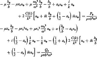
The equations of motion (Eqs. 10 of § 6.8) then become, on dividing throughout the first by ітрЬ3оР and the second by ттрЬ*со2, and omitting the time factor etkr,

FORCED OSCILLATION DUE TO A PERIODIC EXCITATION

(ID

FORCED OSCILLATION DUE TO A PERIODIC EXCITATIONFor the forced-vibration problem, the effect of the structural damping (so far neglected) must be considered, particularly in resonant conditions. The structural damping in aircraft structures is generally small. To account for the damping approximately, let us assume that the actual form of the hysteresis curve is unimportant and that the hysteresis loop can be replaced by an ellipse whose area is the same as the actual one. In other words, we assume that the effect of structural damping is revealed through the energy it dissipates per cycle. Furthermore, following Theodorsen, let us assume that the energy dissipation varies with the square of the amplitude of oscillation. Under these assumptions the effect of damping can be represented by a shift of the phase angle of the elastic restoring force. For aircraft structures the amount of this phase shift is very small, and so the structural damping may be described by a force in phase with the velocity, against the direction of motion, and of a magnitude proportional to the elastic restoring force. Thus in associa­tion with the elastic restoring force — Khh0elkr which acts against the vertical translation, there is a damping force — ighKhh0elkr. gh is called the damping coefficient. The net result is simply that the restoring force terms hKn, aKx be replaced by terms of the form hKh{ 1 + igh), a. Ka(l + iga), or, equivalently, mh coa2 be replaced by &>Ді + igh), соa2(l + iga), respectively. Cf. Appendix 3.
Equations 11, with the above-named modifications for the structural damping, take the form:

FORCED OSCILLATION DUE TO A PERIODIC EXCITATION(12)

Подпись: рттЬ*со2
FORCED OSCILLATION DUE TO A PERIODIC EXCITATION

where

The coefficients A, B, D, E are functions of со, U, gh, gx, and k. take со and к as fundamental parameters and let

The responses h0lb and cc0 depend on the magnitude and phase relations of the excitations p0, q0, the frequency со, the speed of flow U, and the wing’s geometric, elastic, and damping characteristics. Owing to the complicated expressions, the nature of the response can be best seen by examining individual examples.

Let us consider the following particular two-dimensional wing model:*

H = 76, ад =-0.15, xa = 0.25, /у* = 0.388 (20)

b — 5 inches,

<wa = 64.1 radians per second, coh — 55.9 radians per second.

Assume the wing to be excited by a periodic force acting on the elastic axis so that

P0 = const, бо = 0 (21)

Подпись: Kh Подпись: ртгЬгсогрй Подпись: (-)A w Подпись: (22)

It is convenient to define certain static deflection Ast corresponding to P0:

Then, according to Eqs. 16, 17, and 21,

Подпись:(23)

where

|£I – V(EB + F^Xf + (Ex + ga/ir[20]X) І Д| = VVTA?

The phase angle rph between the response h and the exciting force is given by the equation

tan w = ~ ^i(Er + !1ГаХ)

Дд(-£д + /<ra2X) + A j{Ej + go’ftrJ’X)

The response h leads the exciting force if iph is positive.

At a given speed of flow U, the response ratio | hjh3t | can be computed as follows: (1) Assume a value of k. From Table 6.1 find the corre­sponding values of F and G. (2) Calculate the coefficients AIt AB, etc., with the assumed parameters. (3) Since со = kUjb and к and U are specified, со and X — (coa/co)2 can be obtained. (4) A substitution into Eqs. 19 gives Ад and Aj. (5) Obtain the response ratio | h0/hs11 and the phase shift iph from Eqs. 23 and 24.

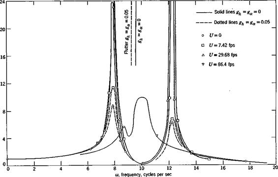
The results of such a calculation are shown in Fig. 6.9 where the response ratios of a wing, characterized by the dimensions and frequencies listed in Eqs. 20, at three speeds of flow U =• 7.42, 29.7, and 86.4 ft per sec, are plotted. It is seen that, as the frequency increases from zero, two peaks of response are reached, one at a frequency close to the natural frequency in bending, and the other at that close to the natural frequency in torsion. These frequencies in still air, V = 0, are 7.92 and 12.37 cycles per second respectively. Two sets of curves are presented: The solid curves are referred to an airfoil without structural damping, gh—g« — 0; and the dotted curves are referred to an airfoil with g%— g* — 0-05, a value probably high for most metal aircraft structures. It is seen that the effect of structural damping on the response is small, except near the peaks.* At zero airspeed, the resonance peaks tend to infinity at the natural frequencies of vibration if the structural damping is zero. With damping gA and ga, the peak responses vary approximately as 1 jgh and l/gx, respectively.

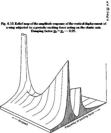
Such response calculations can be repeated for other speeds of flow U. A relief map of the response as a function of U and w may be plotted.

FORCED OSCILLATION DUE TO A PERIODIC EXCITATION

Fig. 6.9. Amplitude response of the vertical displacement of a wing subjected to a periodic exciting force acting on the elastic axis.

FORCED OSCILLATION DUE TO A PERIODIC EXCITATION

Figure 6.10 is such a relief map of the response ratio | hjhst | for the above numerical example, at g — 0.05, for which a critical flutter speed exists. The curves of Fig. 6.9 are the intersections of the relief map with particular planes perpendicular to the U axis. It is seen that, as U increases, the peak response diminishes, until, along one frequency branch, the response becomes negligibly small. Along the other frequency branch, however, a

minimum response is first reached, after which the response increases (usually rapidly) until the flutter speed is reached.

The critical flutter condition is reached when, at certain combinations of U and m, the determinant Д (Eq. 18) vanishes. Then the response ratio I h0/hst I becomes infinity. (Note that the response tends to infinity at the flutter condition, no matter whether structural damping is present or not.) The critical flutter frequency usually lies between the two natural frequencies that exist at zero airspeed.

To find the critical flutter speed and frequency, the characteristic equation

A = 0 (25)

must be solved for the pair of real variables U and со. Since A is complex­valued, both the real and imaginary parts of A must vanish. Equation 25 is actually equivalent to two real equations,

Дл — О, Д7 = 0 (26)

The solution can be obtained as follows. Let a series of values of к be assumed and the corresponding coefficients A, B, D, E calculated. By

FORCED OSCILLATION DUE TO A PERIODIC EXCITATION

l/k

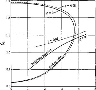
Fig. 6.11. Solution of the flutter determinant.

equating Ад and Д7 given by Eqs. 19 to zero, two quadratic equations in X are obtained. These equations can be solved for X. Since X by definition (Eq. 14) is a positive quantity, only the real positive roots have a physical meaning. Curves of Vx vs. l/k can then be plotted, such as those shown in Fig. 6.11. If the curves corresponding to Дл = 0 and A7 = 0 intersect, the points of intersection determine the values of Vx and l/k at which the determinant A vanishes. Now

FORCED OSCILLATION DUE TO A PERIODIC EXCITATION Подпись: (28)
FORCED OSCILLATION DUE TO A PERIODIC EXCITATION

Hence, the critical flutter frequency and speed are given by

If the curves Дл = 0 and Д7 = 0 do not intersect, there will be no flutter. If they intersect at more than one point, then each intersection represents a critical condition. The one having the lowest value of U is the most important. In general, it represents a transition speed below which the wing is stable and above which the wing becomes unstable. In case of doubt, however, a test of stability by the methods of §§ 6.5 and

10.6 should be made.

For the given example, Fig. 6.11 shows the existence of a critical flutter condition for gh = ga = 0, with

r =3.62, 1.072

к

Hence, the critical flutter speed is

Ua = 90.1 ft per sec and the flutter frequency is

eocr = 9.52 cycles per second

The corresponding values for gh — gx — 0.05 are

UCI = 93.0 ft per sec, cocr = 9.27 cycles per second

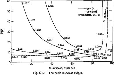
The main feature of the response is given by the peak values on the two ridges of the relief map (Fig. 6.10). It can be shown that, for a fixed value of the reduced frequency k, the response peaks are reached approx­imately where Дд vanishes. Hence, if the values of A7 are calculated for various selected points (l/к, у/Х) along Дн — 0, these values may be used to determine A. In fact,

|A| = |Arl (29)

along the Ar — 0 line. The approximate values of the response peaks can then be determined from Eq. 23, the corresponding « and U being given by Eqs. 28.

Figure 6.12 gives the peak response ridges of the example cited above. The relief map of Fig. 6.10 is constructed on the basis of Fig. 6.12.

If the exciting force is generated by a rotating eccentric weight, the

exciting force is proportional to to2; the response can be obtained from the above by appropriately multiplying the h0lhat curve by a factor to2.

Note that the coefficients of X in Eqs. 26 are nondimensional quantities, depending on the ratios ц, ah, xa, rj, and (oh/wa. Hence, the solution X is nondimensional and does not depend on the absolute values (or physical units) of the semichord b and the frequency coa. For example, if in the example specified by Eqs. 20 the semichord is changed to 2 ft, and the

FORCED OSCILLATION DUE TO A PERIODIC EXCITATION

frequency coa to 48 radians per second, while other quantities (ju, ah, xx, ra2, cojcoa) remain the same, then the critical reduced frequency remains the same, but the critical flutter frequency and speed become, respectively, when g — 0.05,

cocr = 43.6 radians per second, t/cr = 334 ft per sec

EQUATIONS OF MOTION OF A TWO-DIMENSIONAL AIRFOIL

EQUATIONS OF MOTION OF A TWO-DIMENSIONAL AIRFOIL

Let us consider a strip of unit width of a two-dimensional flat-plate airfoil having two degrees of freedom: a bending h (positive downward measured at the elastic axis) and a pitching a (positive nose-up) about the

elastic axis (Fig. 6.7). Let the airfoil be situated in a flow of an incom­pressible fluid at speed U. The equations of motion of the airfoil will be derived by considering the balance of the inertia, elastic, aerodynamic, and exciting forces.

For an element of mass dm situated at a distance r (positive toward the trailing edge) from the elastic axis, the inertia force is

— dm(h + r’d)

* It is interesting to note that, whereas the apparent mass of a flat plate is equal to the mass of a cylinder of air with diameter equal to the chord of the plate, the apparent moment of inertia is only one fourth of the mass moment of inertia of that cylinder of air if that cylinder were solid.

The total inertia force per unit span of the wing is therefore

— J dm(h + r’d) = — (mh + S&) (1)

where m — dm = the total mass of the wing per unit span, slugs, and S = Jr dm = wing static moment about the elastic axis, slug-feet. The integrals are taken over the entire wing chord.

The inertia force exerts a moment per unit span about the elastic axis of amount

— j>(/i + rx)dm = — {LjV – + Sh) (2)

where Ix = r2dm = wing mass moment of inertia about the elastic axis, slug-ft2.

Let the bending and pitching displacements be resisted by a pair of springs at the elastic axis with spring constants Kh (pounds per foot) and Kx (foot-pounds per radian), respectively. The elastic restoring force corresponding to a displacement his — h Kh, in the direction opposing h. That against a is — aKx.

The equations of motion can be written according to the condition that the sum of the inertia and elastic forces and moments must balance the externally applied force and moment. Let the latter be denoted by Qh and Qx, which include the aerodynamic forces and other mechanical excitations. Hence,

mh + Sol + hKh = Qh, Sh + Ia к + — Qx (3)

These equations can be written in a slightly different way by expressing the spring constants in terms of certain frequencies. Consider the airfoil to be so restrained that only one degree of freedom, say h, is permitted. Assume further that no external force is acting. The equation of motion of the airfoil is then

mh + hKh =0 (a = 0) (4)

This represents an independent (uncoupled) harmonic oscillation of frequency

KJm (5)

Hence, we may write

Kh = mcoh2 (6)

Similarly,

Ka = W (7)

where a>x (radians per second) is the uncoupled natural frequency in torsion.

The part of the external forces induced by the motion of the airfoil can
be obtained from the results of the preceding section. The aerodynamic lift and moment about the elastic axis induced by h and a are:

L(t) = 2-rrbpU2j J>(t — г,,) |а'(т0) + h"(r0)

Подпись: (8)Подпись: (9)+ Q — ah) а"(то)] dr0 + pirUh" — афа!’) + pnbU4′

M(T) ^ (2 + ahj 2TTb2pUsj Ф(r — r0) Ci'(r0) + j – h"(r0)

+ ~ a*) a"(To)] *0 + ahbpnU2(h” – афа.")

If we let P(t) and Q(r) denote, respectively, the external applied force (positive downward) and moment (positive nose up) other than the aerodynamic lift and moment, and introduce the dimensionless time t = Ut/b, Eqs. 3 become*

w — /z" + $ — a" + mm^h — — Цт) + P(r)

Подпись: (10)U2 U2

Я – p – A" + /« a" + /a«a2« = M(r) + G(t)

Equations 10 can be solved by the method of Laplace transformation. But a special case is of interest: the steady-state forced oscillation due to a periodic excitation, in which the integrals in Eqs. 9 can be integrated explicitly, thus simplifying the calculations.

UNSTEADY AERODYNAMIC FORCES ON AN AIRFOIL IN AN INCOMPRESSIBLE FLUID

The simplified analysis of the preceding sections are based on the quasi-steady aerodynamic derivatives. We shall now show how the quasi-steady assumptions can be removed. In this and later sections, the results of the linearized aerodynamic theory, as presented in Chapters 12-15, will be used.

In order to show the existence of the critical flutter conditions, we shall first summarize the aerodynamic forces acting on a two-dimensional

airfoil in unsteady motion in an incompressible fluid. The equations of motion of the airfoil are derived in § 6.8. The forced oscillation of the airfoil due to a periodic excitation is then considered in § 6.9. Following this, in § 6.10, the flutter of a two-dimensional airfoil is discussed in general terms, without restricting to the incompressible fluid. The solu­tion of the flutter determinant and a summary of the methods of deter­mining the critical speeds are presented in the last two sections.

The unsteady aerodynamic force acting on a thin airfoil in unsteady

* In the definition of the critical reduced frequency of flutter, со is the frequency at the critical flutter speed, which, in general, differs somewhat from the fundamental frequency of the torsional oscillation of the wing. But, since the flexural rigidity plays only a minor part in the flexure-torsional flutter, the “apparent” reduced frequency as defined above has a physical significance.

motion in a two-dimensional incompressible fluid was obtained by Wagner, Kiissner, von Karman and Sears, and others. Let the chord of the airfoil be 2b, and the angle of attack (assumed infinitesimal) a. Con­sider the growth of circulation about the airfoil which starts impulsively from rest to a uniform velocity U. Let the impulsive motion take place at the origin when г = 9 (Fig. 6.5). The vertical velocity component of the fluid, the so-called downwash, is w = U sin a = 17a on the airfoil, since the flow must be tangent to the airfoil. Then, on the physical assumption that the velocity at the trailing edge must be finite, one derives the lift due to circulation on a strip of unit span as a function of time:

Lx = IrrbpUw Ф(т), Ф(т) = 0 if т < 0 (1)

where

т = Ut/b (2)

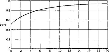
is a nondimensional quantity proportional to time. The function Ф(т), called Wagner’s function, is illustrated in Fig. 6.6. An approximate

UNSTEADY AERODYNAMIC FORCES ON AN AIRFOIL IN AN INCOMPRESSIBLE FLUID

r, distance traveled, in semichords Fig. 6.6. Wagner’s function for an incompressible fluid.

expression which agrees within 2 per cent of the exact value in the entire range 0 < t < oo is given by Garrick15-9’ 15-17:

ф(т) – і _ JL_ (T > 0) (3)

4 – f – t

Another approximate expression is given by R. T. Jones15-43:

Ф(т) = 1 – 0.165<?~°’0455t – 0.335е~аз00т (т > 0) (4)

whereas W. P. Jones gives15-80

Подпись:Ф(т) = 1 – 0.165e-°-04lT – 0.335e-°-32r

The expression 4a gives slightly better approximation than Eq. 4 for

T < 2.2.

The exact form of Ф(т) is the following (see § 15.1)

ф(т) = l – Ґ “{(*„ – Kxf + ттЦі0 + dx (5)

Jo

where K0, Kx /„, Ix are modified Bessel functions of the second and first kind, respectively, with argument x implied. It is seen that half of the final lift is assumed at once and that the lift approaches asymptotically its steady-state value 2irbpUw when т -> со. The center of pressure of this lift (due to circulation) is at the 1/4-chord point behind the leading edge.

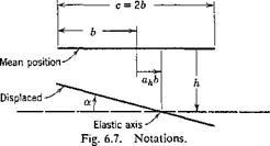
Let us now consider a more general type of motion. Let the airfoil have two degrees of freedom: a vertical translation h, called bending, positive downward, and a rotation a, called pitching, positive nose up, about an axis located at a distance ahb from the mid-chord point, ah being positive toward the trailing edge (Fig. 6.7).* The flow is assumed to be two-dimensional, h and a are infinitesimal, and the mean flow speed U is a constant. In this case part of the lift arises from circulation, and part from noncirculatory origin—the so-called “apparent mass” forces.

Wagner’s function gives the growth of circulation about the airfoil due to a sudden increase of downwash which is uniform over the airfoil. For a general motion having two degrees of freedom h and a, the down – wash over the airfoil is not uniform. Now, in the theory of oscillating airfoils, it can be shown that for bending and pitching oscillations the circulation about the airfoil is determined by the downwash velocity at the 3/4-chord point from the leading edge of the airfoil (§ 13.4). By a reciprocal relation between the harmonic oscillations and the response to unit-step functions (§ 15.1), and the principle of superposition, this result holds also for arbitrary bending and pitching motions. Hence, if we replace w in Eq. 1 by the increment of downwash at the 3/4-chord point, the circulatory lift can be obtained.

The downwash at the 3/4-chord point due to the h and a degrees of freedom consists of the following: (1) a uniform downwash corresponding to a pitching angle a, w — V sin a = t/a (a being infinitesimal), (2) a uniform downwash due to vertical translation h, which may also be written

Подпись:
the nondimensional time t, and a dot denotes a differentiation with respect

* These notations are different from those of the preceding sections. In the airfoil theory (Chapters 12-15), the origin of reference axes is usually taken at the mid-chord point, and the semichord length b is taken as the characteristic length. In keeping with these standard notations, the symbols are redefined in Fig. 6.7.

to the physical time t, (3) a nonuniform downwash due to a, its value at

the 3/4-chord point being (V2 — ah)b — or (1/2 — ah)Ua!.

dt

Summing up, we find

w(r) = Ua(r) + jh'(r) + (i — ah)Ua(r) (6)

In the time interval (r0, r0 + dr0), the downwash w(r0) increases by an

amount сіт0. When dr0 is sufficiently small, this may be regarded dr0

as an impulsive increment and the corresponding circulatory lift per unit span is

Подпись: dLx = 2ттЬрІіФ(т, dw(r0)

■ t0) j— «To for T 3» t„ drn

By the principle of superposition which holds when w remains small, we have the circulatory lift per unit span for arbitrary time history of w:*

Cr dw

Lfj) = 2-rrbpU Ф(т — r0) — (r0) dr0 (7)

J— CO UTq

Подпись: L1(r) = 2-nbpU UNSTEADY AERODYNAMIC FORCES ON AN AIRFOIL IN AN INCOMPRESSIBLE FLUID Подпись: (la)
UNSTEADY AERODYNAMIC FORCES ON AN AIRFOIL IN AN INCOMPRESSIBLE FLUID

where the lower limit is taken as — oo, meaning before the very beginning of motion. If the motion starts at time r = 0, w — 0 for r < 0, Eq. 7 reduces to

where w0 is the limiting value of w(r) when r -> 0 from the positive side. f It is, of course, to be remembered that Ф(т — r0) = 0 if r < r0. Com­bining Eq. 7 with Eq. 6, we obtain:

Подпись: LI(T) =UNSTEADY AERODYNAMIC FORCES ON AN AIRFOIL IN AN INCOMPRESSIBLE FLUIDПодпись: dr0 (8)*'(t0) + ~bh"(r0) «ftj a"(To)

An expression corresponding to Eq. la can be written down if the motion starts at time r = 0.

When the airfoil has a general motion, the lift and moment of the noncirculatory origin (the apparent mass forces) must be added. The resultant lift and moment include the following terms:

1. A lift force with center of pressure at the mid-chord, of amount equal to the apparent mass prrb2 times the vertical acceleration at the mid-chord point:

L2 = pnb2(h — ahba.) = pnU2(h" — ahboc") (9)

* Duhamet’s integral. See §8.1.

t The first term in Eq. 7a gives the effect of initial disturbance. It can be obtained formally from Eq. 7 by noticing the jump of w(t0) at r0 = 0.

2. A lift force with center of pressure at the 3/4-chord point, of the nature of a centrifugal force, of amount equal to the apparent mass рттЬ2 times Ш.. (This term is, however, circulatory.)

L3 = рттЬ2Ш. = рттЬ U2a (10)

3. A nose-down couple equal to the apparent moment of inertia* рттЬ2(Ь2/&) times the angular acceleration к:

Подпись: рттЬ4, M«=~ — K = Подпись:pnb2U2 „

8

The total lift per unit span is then

L = + L% – p L3 (12)

The total moment per unit span about the elastic axis is

M = (i + ajbL, + ahbL2 – (i – ah)bL3 + Ma (13)

All these are valid for a two-dimensional flow of an incompressible fluid.

THE EFFECT OF STRUCTURAL PARAMETERS OF THE WING ON THE CRITICAL SPEED OF THE TORSION-FLEXURE FLUTTER

Under the assumptions of § 6.3 and using the method of § 6.4, Grossman proved a number of relations expressing the effects of structural parameters of the wing on the critical torsion-flexure flutter speed :f

1. A simultaneous change of the flexural and torsional rigidities by a factor n changes both the critical flutter speed and the flutter frequency by a factor Vn, and leaves the critical reduced frequency unchanged.

For, other things remaining equal, a multiplication of El and GJ

by a factor и’changes the values of the coefficients au, a22, etc., by factors listed below, as can be easily verified according to Eqs. 4, 6, 9 of § 6.4:

Coefficients changed by a factor n: au, a22, Cx, D1; E2, M.

Coefficients changed by a factor n2: Ev N.

Coefficients unaffected: hX2, b22i d^, d±2, d2x, d22, clx, c12 = c2X, c22,

THE EFFECT OF STRUCTURAL PARAMETERS OF THE WING ON THE CRITICAL SPEED OF THE TORSION-FLEXURE FLUTTER

Equations 7 and 10 of § 6.4 then show the conclusion of the theorem at once. The constancy of the reduced frequency follows by definition.

The effect of the individual changes of the flexural and torsional rigidities cannot be stated in such general terms. Examples of flutter analysis generally show that, when the torsional rigidity alone is increased, the flutter speed is also increased, but, when the flexural rigidity alone is varied, the change in critical flutter speed is small. The flutter speed reaches a minimum when the flexural rigidity becomes so high that the frequency of (uncoupled) flexural oscillation is equal to that of the (un­coupled) torsional oscillation. Further increase of flexural rigidity increases the flutter speed.

An important consequence of the above result concerns the accuracy required in determining the rigidity constants: It is permissible to admit considerable error in the flexural rigidity of a wing without causing serious error in the calculated critical flutter speed.

2. A similar investigation gives the following: A change in all the geometric dimensions of a wing by a factor n without a change in the elastic constants (E and G) has no effect on the magnitude of the critical speed, but changes the flutter frequency by a factor 1/я. The critical reduced frequency remains unchanged.

As for the effect of variation of individual geometric parameters, the results of sample calculations can be stated most concisely in the following form, which, however, cannot be proved without introducing further assumptions in addition to those stated in § 6.3:

3. When the characteristic geometric dimensions of a wing are varied individually, with the mass density and elasticity distributions remaining unchanged (while the absolute values of the mass density and the torsional stiffness may vary), the “apparent” reduced frequency for torsion-flexure flutter

THE EFFECT OF STRUCTURAL PARAMETERS OF THE WING ON THE CRITICAL SPEED OF THE TORSION-FLEXURE FLUTTER(1)

remains approximately unchanged. In the formula above, c represents
the chord length at a reference section, and coa the fundamental frequency of the torsional oscillation of the wing.*

Equation 1 is an approximate empirical rule whose validity must be questioned when unconventional wing designs are considered.

4. The effects of the relative positions of the elastic, inertia, and aero­dynamic axes are so important that each particular case should be com­puted separately. Generally speaking, the closer the inertia and elastic axes are to the line of aerodynamic centers, the higher is the critical flutter speed.

THE STABILITY OF A DISTURBED MOTION

Let us now return to the general problem, and consider the stability of the motion of the cantilever wing of § 6.3 at any speed of flight U, following

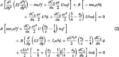
an initial disturbance. The equation of motion is given by Eqs. 3 of § 6.3 and the boundary conditions by Eqs. 4 of that section. The solution can be expressed in the form

h = A f(y)eu, а. = Вф(у)еи (1)

where А, В, Я are constants; Z, f(y), ф(у) are to be determined by the differential system, and A, В by the initial conditions. To obtain an approximate solution, Galerkin’s method may be used. We shall assume approximate forms off(y), ф{у) to be known (as discussed in § 6.4). Let us substitute Eqs. 1 into Eqs. 3 of § 6.3, multiply the first equation by f(y) and the second by ф(у), integrate both with respect to у from 0 to /, to obtain two linear homogeneous equations for A and B, which are exactly the same as Eqs. 3 of § 6.4, except that the factor /со in those equations must be replaced by Z. For a nontrivial solution corresponding to a disturbed motion, the determinant of the coefficients of A and В must vanish. This determinantal equation, known as the characteristic equation, may be written as

A0№ + B0P + QA* + D0Z + E0 = 0 (2)

where

A о = A j, B0 = BjU

C0 = C, + C2U2, D0 = D, U + D2U* (3)

E0 = Щ. -!- E2U2,

and Ab Blt etc., are given by Eqs. 6 of § 6.4.

From the discussion in § 6.3, it is seen that the condition for stability of the disturbed motion is that the real parts of all the roots of the characteristic equation be negative. The necessary and sufficient con­dition for this is that the coefficients A0, B0, C0, D0, E0 and the Routh discriminant

R = B0C0D0 – B02E0 – D2A0 (4)

have the same sign.* It can be shown on the basis of Schwarz inequalityf

* See Appendix 2.

t For arbitrary functions f^x) and/2(ж), we have

J[a /)(*) 4- Д/2(ж)]г dx > 0 i. e.

“2l/i2(®) dx + /і(ж) /2(ж) dx + dx^O

Since this is a positive definite function of a,(3, the discriminant must be negative, which leads to Schwarz inequality

lifX*) dx][$ff(x) dx] > Шх)/2(х) dx?

that the coefficient A0 is always positive. Hence the conditions of stability are

B0 > 0, C0 > 0, D0 > 0, E0 > 0, R > 0 (5)

These inequalities are satisfied when U is very small, because it is shown in § 6.3 that the disturbed motion is stable. As V increases, the coeffi­cients B0, C0, • ■ R vary. Since B0 = BflJ and B1 does not depend on U, B0 is positive at all values of V > 0. As for C0 and D0, we shall show that E0 and R become zero before C0 and D0. For, if D0 = 0, then

R = – W (6)

which shows that either E0 or R must be negative. Similarly, if C0 = 0, then

r = — ад – ад (7)

which again shows that either E0 or R must be negative. Hence, as long as Eq and R remain positive, C0 and D0 must be positive.

The stability is then determined by the signs of E0 and R. If E0 and R0 remain positive, the motion is stable. If either one becomes negative, the motion is unstable.

The physical meaning of the critical condition E0 = 0 or R = 0 can be clarified as follows. When Eq = 0, Eq. 2 has a root Я = 0. Hence, according to Eqs. 12 of § 6.3, a condition of wing divergence is reached. The divergence speed is given by

THE STABILITY OF A DISTURBED MOTION

which agrees with the result of § 3.4, CM being the coefficient of aero­dynamic moment about the elastic axis.

The condition R = 0, on the other hand, corresponds to the critical flutter condition. For, a substitution of A0, B0, etc., from Eqs. 3 leads to

R = иьт – г МІР + N) = 0 (10)

which is exactly the critical flutter equation 8 of § 6.4, except for the factor Vz. That Eq. 10 has a root U — 0 simply reflects the fact that the structure may oscillate in still air, which is a natural consequence of our assumption that the viscosity of the air and the internal damping of the structure are negligible.

Combining the above results with the discussion at the end of § 6.3, we see that, at U slightly larger than the smallest critical flutter speed, the motion will be unstable if R < 0. The very special case that R becomes zero at Ua but becomes positive again at supercritical speeds occurs only when R reaches a relative minimum at Ua. This is possible if and only if[18]

Подпись: d2R dU2Подпись: > 0(11)

Using Eq. 10, we see that the dimensions and the aerodynamic character­istics of the wing must be such as to satisfy the conditions

M2 = 4LN and M < 0 (12)

If Eq. 12 is satisfied, then the critical nature of the motion at the speed Uct is only superficial. For, at speeds differing slightly from UCI (either larger or smaller), the disturbed motion is stable. If Eq. 12 is not satisfied, then the speed Uct is truly critical; for supercritical speeds the motion diverges. The exacting condition 12 has little chance of being satisfied in practice.

This method of stability investigation can be applied to other aero – elastic systems whenever the time variable appears in the governing equation as derivatives of finite order (see footnote, p. 228). The general method consists of deriving a characteristic equation by a substitution such as Eq. 1, and then check the signs of Routh or Hurwitz discriminants (Appendix 2).

APPROXIMATE DETERMINATION OF THE CRITICAL SPEED BY GALERKIN’S METHOD

We shall consider the motion at the critical flutter condition and determine the critical speed of flight. In the following, therefore, U represents the Ua of the preceding section. The motion is harmonic and representable as

h = Af(y)eM, а = Вф(у)еш (1)

where со is real and A, В are complex constants.

We assume A and В to be of the same dimensions as h and a, respec­tively, and f(y), ф(у) to be dimensionless. Substituting Eqs. 1 into the differential equation 3 of § 6.3, and canceling the factor e’“" throughout, we obtain

APPROXIMATE DETERMINATION OF THE CRITICAL SPEED BY GALERKIN’S METHOD

These are simultaneous differential equations with complex coefficients. The boundary conditions are given by Eqs. 4 of § 6.3, provided that the h and a functions were replaced by/and <f>.

As a first approrximation to the critical speed and frequency, the method of Galerkin may be used.118 Assume that the functions f(y) and <j>(y) are known and real valued. Multiplying the first of Eqs. 2 by f(y) dy and the second by ф(у) dy, and integrating from 0 to /, we obtain

A(an — cno)2 + ia>Udn) + B(c12u>2 — b12U2 — /со Ud12) — 0 A(c21oj2 — ia>Ud21) + B(a22 — c22a>2 b22U2 + imUd22) = 0

where*

APPROXIMATE DETERMINATION OF THE CRITICAL SPEED BY GALERKIN’S METHOD

* Note that, iff{y) and ф(у) represent the uncoupled flexural and torsional modes of the wing in a vacuum, respectively, the ratio anlcn represents the square of the frequency of the flexural oscillation, and a22/c2= that of the torsional oscillation of the wing.

The homogeneous equations 3 admit nonvanishing solutions A, В only if the determinant of their coefficients vanishes. This determinant being complex, both the real and imaginary parts must vanish. On setting the determinant to zero and separating the real and imaginary parts, we obtain two equations:

The sign in front of the radical must be chosen in such a way as to give the smallest positive value of U2.

Thus a solution can be obtained if the flutter modes / and ф are known. But they are not known at the beginning. Hence, it is necessary to approximate them on the basis of empirical information.[17] As a simple approach,/and ф may be assumed to be the fundamental modes of purely
flexural and purely torsional oscillations in still air, of a cantilever beam of uniform cross section:

J{y) — cosh ку — cos ку — 0.734 (sinh ку — sin ку) (11) where к = 1.875//, and

ф(у) = sin^ (12)

For these functions, tables for the integrals off2(y), ф2(у),/(у)ф(у), etc., are available.6-25

When the distances from the centers of mass to the elastic axis are large, or the wing planform is such that the oscillation modes differ considerably from those of a uniform beam, better results can be obtained by assuming f(y) and ф(у) as the coupled flexure-torsional oscillation modes of a wing. The predominantly torsional mode should usually be used. Sometimes it is advantageous to use the uncoupled flexure and torsion modes of the actual wing for/ and ф.

Corresponding to the two solutions of V2 from Eq. 10, there are two values of со2 from Eq. 7. Usually the smaller t/2 is associated with the higher со2; for, in Eq. 7, the coefficients Bx and Dx are always positive, whereas Z)2 is negative if the elastic axis lies behind the 1/4-chord point, as is usually so. Since, for conventional wings the torsional frequency (in still air) is higher than the flexural, the above conclusion indicates that the flutter mode is generally predominantly torsional.

It has been shown by a simple example in § 1.9 that the oscillations at different spanwise coordinates of a beam of variable cross section with damping are out of phase. Since at the critical flutter condition the aerodynamic force has a component proportional to dh/dt and Эа/Эt, (of the nature of a “damping” force), it is natural to expect that the flutter mode is also generally out of phase in the spanwise direction Mathe­matically, this means that the functions Дг/) and ф(у) must have complex coefficients (see § 1.9). This is actually true, but the change in phase angle along the span is generally small. By assuming f(y), ф(у) to be real func­tions, little error will result. On the other hand, the ratio AjB, solved from Eqs. 3, when the critical value of со and U are used, is generally com­plex, indicating a shift of phase between the flexural and torsional motion. This phase shift is of fundamental importance in governing the energy exchange between the wing and the flow, as we have shown in § 5.4.

QUASI-STEADY AERODYNAMIC DERIVATIVES

In an unsteady flow, the fundamental equation 2 of § 6.1 does not hold because y(x) now consists of both free and bound vortices. Moreover, since the lift, and hence the vorticity strength, varies with time, vortices

У

Подпись: и

…. іепгпу w

<-

"h

c

Fig. 6.2. Unsteady flow over a two-dimensional airfoil.

must be shed at the trailing edge of the wing and carried downstream by the flow. The reason for this is that the total circulation in a contour enclosing all the singularities (Fig. 6.2) must remain zero in a nonviscous fluid. Therefore every vortex element on the wing must be balanced by another in the wake. The vortices in the wake, having no force to support

them, cannot have relative velocity with the flow and hence move down­stream along the streamlines. These wake vortices, however, induce vertical components of velocity on the wing, and therefore the second fundamental equation (Eq. 4 of § 6.1) also becomes invalid.

In order to make a simplified analysis, let us introduce the following quasi-steady assumption: The aerodynamic characteristics of an airfoil whose motion consists of variable linear and angular motions are equal, at any instant of time, to the characteristics of the same airfoil moving with constant linear and angular velocities equal to the actual instantaneous values. The inclination of the flow-velocity vector to the profile is also taken to be constant and equal to the actual instantaneous inclinations. Thus, at any instant of time, we assume that Eqs. 2 and 4 of § 6.1 hold, in spite of the objections named above.

Under the quasi-steady assumption, the results of the last section can be applied directly. Let us consider a flat plate in a stream whose velocity at infinity is U in the ж-axis direction. Let the plate have two degrees of freedom: a vertical translation h and a rotation a about an axis located at x0 behind the leading edge, h being positive downward and a positive nose up, both measured from the ж axis. Let the coordinate system be as shown in Fig. 6.2. As before, the plate will be replaced by a vortex sheet, and the camber line, when h — a. = 0, is a line Y(x) = 0.

QUASI-STEADY AERODYNAMIC DERIVATIVES

At a point ж on the airfoil, the vertical velocity component is

Подпись: Vi U Подпись: 1 dh i fr0 — x) da. - — A - — Подпись: (1)

The instantaneous slope of the airfoil at ж is ■— a. As the fluid velocity must be tangential to the airfoil, the vertical component of fluid velocity V{ on the airfoil must satisfy the equation

v{ is the velocity induced by the vorticity yfr). Equation 1 is the equiv­alent to Eq. 5 of § 6.1. A comparison with the fundamental equations of § 6.1 shows that everything is the same except that the term dY/dx in that section must now be replaced by

Подпись: l_ dh Udt + (ж0 — ж) da – —

Making this replacement in Eqs. 15 of § 6.1, we obtain, from Eqs. 16 and 14 of §6.1

Подпись: (2)^ dCj, J 1 dh 1 /3 da

Should хл and U be zero, Eqs. 3 would be reduced to two independent equations, one for h and one for я. The terms involving xx and U indicate inertia and aerodynamic couplings.

Since Eqs. 3 are linear equations with constant coefficients, the solution is a sum of linearly independent solutions of the form

h = Af(y)eu, a. = В ф(у)еи (5)

where Я,/(у), ф(у) and А, В are to be determined from Eqs. 3 and 4, and the initial conditions. Since the solution of a differential equation depends continuously on the coefficients of the equation, and since the coefficients of Eq. 3 vary continuously with U, the constant Я will vary continuously with U. In general, Я is a complex number. Let

Я = p + щ (6)

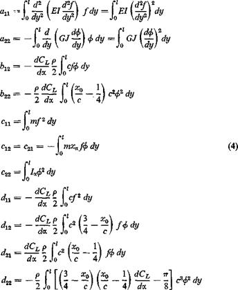
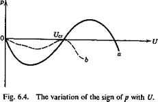
When p is positive, the amplitude of the motion will increase with increas­ing time. When p is negative, the opposite is true. If p is negative at иъ and positive at U2, (U2> U{), then there exists at least one value of U, say U0, between U1 and U2, at which p vanishes. At U0, p is purely imaginary, corresponding physically to a simple-harmonic motion. Such a speed will separate the speed range in its neighborhood into two regions, in one of which p < 0, where the motion is damped and stable; in the other p > 0, where the amplitude increases with time and is unstable.

Beginning with U = 0, let us gradually increase the speed of flow and consider the variation of p with U. When U = 0, the motion is simple

harmonic, and so p = 0, as is shown in § 1.10 (material and air damping neglected). Next let U be a very small positive number. We shall show that p is small and negative. Instead of solving the differential system directly, let us recall that p < 0 implies that the motion is damped. For a free system this imples that the wing is losing energy to the surrounding air. Hence, it is sufficient to consider the energy relations. When U is small, the solutions h and oc differ only slightly from those obtained for U — 0. Free oscillation in still air has been investigated in § 1.10, where it is shown that the solution can be written as

h — A fly) sin qt, а — В ф(у) sin qt (7)

QUASI-STEADY AERODYNAMIC DERIVATIVES Подпись: (8) (9)

where A, B, q are real numbers and f ф are real functions, h and a are in phase with each other, so the initial phase angles may be omitted from Eqs. 7 by suitably choosing the origin of time. The oscillation modes h and a at very small V will be assumed to be given by Eqs. 7. Substituting Eqs. 7 into Eqs. 2 to obtain L and M, we can compute the energy gain per unit span of the wing at a spanwise station у in each complete cycle of oscillation:

where

QUASI-STEADY AERODYNAMIC DERIVATIVES(10)

Evidently ax > 0. a2 reaches a minimum at xfc — x/2 where it becomes zero if dCJda — 2тг, and is positive if dCL/da < 2tt. Furthermore, if dCjjda < 2tt, the discriminant of Eq. 9 is negative; i. e.,

у – axa2 <0 (11)

For we may reduce the discriminant into the following form:

Подпись: 1Подпись: -/У-2 / 277 C2/2<P

dCjda) 16

which is zero when dCL/da = 2n and is negative when dCLjda < 2n. Therefore the quadratic form of A and В in the parenthesis of Eq. 9 is
nonnegative,* and Eq. 9 shows that the airfoil cannot gain energy from the flow. In other words, when the speed of flow U is infinitesimal, the flow is stable and p is negative. f Since p = 0 when U = 0, it is evident that p will remain negative until it becomes zero again at certain higher value of U, say Ua (see Fig. 6.4). For speeds U > UCI> p may become positive, corresponding to an unstable motion.

We shall call the speed at which p — 0 a critical speed. We have shown that between U = 0 and U„ the torsion-flexure motion of the cantilever wing is stable when dCLjda. < 277. At the critical speed, two cases are possible: Either q (the imaginary part of A) vanishes, or it does not vanish.

QUASI-STEADY AERODYNAMIC DERIVATIVES

If q — 0, then the displacements h and a are independent of time, but the structure has lost its power to recover its original form when disturbed. The wing is said to be in critical divergent condition. If q Ф 0, the motion is harmonic with an indefinite amplitude. It is said to be in the critical flutter condition. Hence,

p = 0, q — 0 implies divergence p — 0, q Ф 0 implies flutter

In both cases the aeroelastic system may be said to be neutrally stable.

The continuity argument cannot establish definitely the sign of p for U > C/cr. As shown in Fig. 6.4, at UCT there are two possibilities. The curve of p vs. U may cross the U axis to p > 0 for U > UCI (curve a), or it may have a horizontal tangent at f/cr and then turn back to the lower side (curve b). More careful study in the neighborhood of UCI is necessary

* A quadratic form ax2 + bxy + су2 can never change its sign for all real values of (ж, у), if

b2 — 4ac < 0

t This result has no universal validity since the case xjc = 1/2, dCflda = 2-n must be excepted. Nor is it true for all other types of oscillations. For example, in tab flutter problems, it may happen that a disturbed motion is actually unstable for zero airspeed upwards for bad values of tab frequency and mass balance. In general, a test of stability is needed. Such a test will be discussed in § 6.5 and in § 10.6.

to establish the tendency definitely. In practice, the first case is what generally occurs: The motion at supercritical speeds is unstable.

When we continue curve a or b further for larger values of U, it may cross the U axis again. Hence, higher critical speeds may exist. But, since aircraft flight starts from U = 0 and increases continuously, and since generally no instability can be tolerated, the flight speed cannot be permitted to be larger than the first critical value. Thus the finding of the first critical speed is the main object of flutter analysis.

That only the critical speed is of interest implies the following important facts:

1. Only undamped harmonic oscillations are of interest. Hence the aerodynamic coefficients need only be evaluated for harmonic motions.

2. At the critical condition, the amplitude of oscillation may be con­sidered as infinitesimal. There is no need to discuss finite deformations. The linearized aerodynamical theory and the linearized equations in elas­ticity can thus be justified in most cases.