Category BASIC AERODYNAMICS

Angular Velocity and Strain

In general, as a fluid particle moves from point to point in a flow field, it rotates and its shape is distorted (i. e., strain). In this section, the rotation or angular velocity of a moving fluid particle is defined in terms of derivatives of the velocity components of the particle. Any deformation of the particle shape is due to viscous-shear effects, which are absent in the perfect-fluid model considered in this chapter. An expres­sion for strain is needed later in the development of the viscous-flow terms in the conservation equations (see Chapter 8) and is easily obtained simultaneously with the rotation effects. Hence, the strain terms are derived here and then set aside for later use.

Rotation is defined as a property of the fluid particle and not of the global flow field. Thus, for example, a flow field with circular streamlines under certain circum­stances might have zero rotation if individual particles move along the streamlines without spin. In considering the rotation of a solid body (e. g., a spinning flywheel), it is sufficient to determine angular velocity simply by making a straight line on the flywheel and a reference line on a fixed surface. The time rate of change of the angle made by the line marked on the wheel with respect to the fixed reference line is the angular velocity of the flywheel.

A more general definition is necessary for a moving fluid particle because it can deform. Of course, the general definition of rotation for a fluid particle when
Подпись: У. v, Angular Velocity and Strain
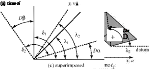
Подпись: Figure 4.1. Deformation and rotation of a moving fluid particle.

applied to a solid-body rotation problem must produce the familiar answer. Consider a moving fluid particle of infinitesimal size in a two-dimensional flow in the (x, y) plane at an arbitrary initial time t1. For example, assume that at time t1, the particle is a rectangle. The assumption of a rectangular shape is, of course, not a requirement; use of a more general shape leads to the same results. Now, imagine that the molecules making up the straight edges of the particle are painted and that a straight diagonal is drawn between two corners of the rectangle (Fig. 4.1(a)).

Take a snapshot of this particle and, on the photographic negative, define the angle 51 as the included angle in the corner (here, 90°) and the angle X to be the angle that the diagonal makes with a horizontal datum parallel to the x-axis. Now, imagine that the fluid particle moves and distorts and that a second snapshot is taken at a later time, t2 (Fig. 4.1(b)). Although the particle distorts, the lines defining the angles still may be considered straight because the element is infinitesimally small. Next, mark each negative with a dot at the lower left corner of the fluid particle, superpose the two negatives, and put a pin through the dots (Fig. 4.1(c)). Such a superposition eliminates the translation of the particle between snapshots.

Now define:

DX

1. rotation or angular velocity =

„ D5 Dt

2. strain = Dt = _£xy

Notice that the time rates of change of the angles are written with an uppercase D because these are rates of change with respect to a moving fluid particle. The sub­script xy indicates that this is the strain in the x-y plane, and the subscript z indi­cates that this is rotation in a plane perpendicular to the z-axis. These subscripts are necessary because two other planes in three-space could be drawn and other appropriate expressions defined.

Figure 4.1 shows that:

1 П 1

X, = -5, = — and X2 =Da +—52 =Da + — — + Dp-Da I. 1 2 1 4 2 2 2 21 2 F 1

Thus, rotation wz is given by:

„ n DB Da

Da + — + —^—- —

4 2 2


n

4


w = — = lim 1= lim

z At Dt->0 I At I Dt^Q


Dt


Подпись: Dp Da Dt DtDX. 1

— = w z = rotation = –

Dt z 2

Similarly, 5, = — and 52 = — + Dp – Da. Thus:

2 + Dp-Da


— = – e = lim JAA1= lim

Dt xy At^Q I At I Dt^Q


Dt


D5 Dp Da t. Da Dp

— = ———– = strain =—————– .

Dt Dt Dt xy Dt Dt

At first glance, it appears that not much was accomplished because rotation and strain were expressed in terms of other variables and in a more complicated way. However, these formulations allow rotation and strain to be expressed in terms of velocity-component derivatives.

Next, recast Fig. 4.1(c) as Fig. 4.2 and recognize why the angles Da and Dp are generated. It is because the “painted” molecules that comprise the edges of the fluid particle are moving with increasing speed in both the x – and y-directions the farther the molecule is located from the corner. (Recall that the gross trans­lation components u and v of the particle were eliminated in the superposition in Fig. 4.1(c).)

Because Fig. 4.2 describes the limit as Dt ^ Q, the paths of the painted mol­ecules may be represented accurately as straight lines even though they are actually circular arcs. In this short time interval, assume that the molecule farthest from the center along the x-axis has moved a distance h. Then, with the tangent of the angle being equal to the angle itself for a small angle:

Angular Velocity and Strain

Da_ h _ (relative velocity)(tae mterval)

dx dx

from which it follows that:

Da _ dv Dt dx

The student should prove by a similar argument that:


dx


(4.1a)


Angular Velocity and Strain

De_-d£. (4.1b)

Dt dy

Note from Fig. 4.1(c) that an arbitrary counterclockwise positive sign was given to Da and Dp. Because Fig. 4.2 indicates that Dp/Dt is positive but that the rate of change of и with respect to y is negative, a compensating minus sign must be inserted into Eq. 4.1b, as shown.

Подпись: z Подпись: 'dv ydx Подпись: du ' дУ / Подпись: (4.2)

Finally, substituting Eq. 4.1 into the definitions of rotation and strain, the desired result is obtained—namely, that these definitions are expressed now in terms of definable and measurable local properties of the flow field. Thus, the rotation in the x-y plane is given by:

Angular Velocity and Strain Подпись: dv + du dx dy Подпись: (4.3)

Substituting Eq. 4.1 into the definition for strain yields:

Expressions similar to Eq. 4.3 likewise can be derived for exz and eyz. The concept of strain is discussed in more detail and applied in Chapter 8. Eq. 4.3 is not needed at this time.

Подпись: ю_ю x i + ю y j + ю zk Подпись: dw dy Подпись: dv_' dzy Подпись: ( du Angular Velocity and Strain Подпись: (4.4)

Analogous expressions for rotation rax and юу can be derived similarly in the other two orthogonal planes. These three expressions for rotation represent the components of the angular velocity of a fluid particle in three-space and may be thought of as the three components of an angular velocity vector. Thus,

A flow is said to be irrotational if the magnitude of this angular velocity vector is identically zero; that is, all three components of the rotation vector are zero. Flows that are irrotational are demonstrated as far simpler to analyze than those that are not. It might seem that irrotational flows would be such special cases as to be of little practical importance. If we consider the velocity profile within a boundary layer in two dimensions (cf. Fig 2.3, where du/dy >> dv/dx) or realize that the large shearing action within the boundary layer causes the fluid particles present there to “spin,” then it is clear that a viscous boundary layer is a region of rotational flow. How­ever, it happens that outside the thin boundary layer on a body, the flow can be

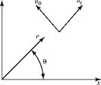
Figure 4.3. Polar-coordinate notation.
Angular Velocity and Strainirrotational; hence, inviscid flow is irrotational. An exception occurs when entropy gradients may be present, such as behind a curved shock wave in a supersonic flow. Of course, the entire flow field near the body can be rotational if there is a source of vorticity that causes the flow field to be rotational far upstream. The word vorticity is used often instead of rotation; it differs by only a factor of two, as discussed in the next subsection.

The expression for angular velocity can be written readily in polar coordinates. Such coordinates are frequently of great value in analyzing flow fields, especially those involving curved streamlines. A detailed list of the fundamental fluid equations in various coordinate systems is included in the appendixes. The two velocity-vector components at a point in a polar-coordinate frame are shown in Fig. 4.3.

In polar coordinates (Fig. 4.3), the angular velocity expression is:

duB 1 dr r


dur

1q


1

2


(4.5)


z


в


Angular Velocity and Strain

In this derivation, both sides of the benchmark fluid particle considered in Fig. 4.1 are assumed to rotate with time in a counterclockwise direction. The student should verify that the same results for ю and exy are obtained if the rotations of both sides are assumed to be clockwise or if one is taken to be clockwise and the other counterclockwise.

example 4.3 Given: A physically possible flow field is steady, incompressible, and two-dimensional and it has circular streamlines; it is also irrotational.

Required: Determine the behavior of the tangential velocity component of this flow field.

Approach: Because the flow field is physically possible, continuity must be satis­fied. Thus, Eq. 3.52 is needed, as well as the irrotationality condition that ю = 0 in Eq. 4.5.

Solution: If the flow has circular streamlines, it follows that ur = 0 and that uB = Krn, where K is a constant and exponent n is to be determined. Next, write the vector continuity equation (Eq. 3.52) in polar-coordinate form:

Подпись: duB "эВ dur 1

dr r

Then, substitute these expressions for the velocity components ur and ue into

the continuity equation. This leads to the requirement that — (Krn) = 0, which

оЄ

is true for any value of the exponent n. Thus, the use of the continuity equation

did not determine n; any value leads to a physically real flow.

In addition, we required that the flow must be irrotational, meaning that Eq. 4.4 must apply with raz= 0. Substituting the expressions for ur and ue into Eq. 4.4 and performing the differentiation, irrotationality demands that

nKr n-1 + Kr n-1 = 0 = rn-1K(n + 1).

This states that if n = -1, the flow field is irrotational but that the expression for the rotation, raz, is indeterminate at the origin (r = 0). Thus, the flow field described by ur = 0 and ue = K/r satisfies continuity and is irrotational every­where except at the origin. To settle the question of what happens at the origin requires the development of additional building blocks (see Section 4.6). An irrotational flow with circular streamlines is an important special case called a vortex.

Appraisal: This flow has circular streamlines, yet the fluid particles in the flow exhibit zero rotation. The fluid particles are behaving like the seats on a Ferris wheel in that the angle between a horizontal datum and the diagonal in Fig. 4.1 does not vary with time. If the flow field had circular streamlines and was exhib­iting solid-body rotation—as if it were instantaneously frozen and rotating like a wheel—then ue = Kr and Eq. 4.5 yields ю = K. This simply states that the gen­eral angular velocity expression, Eq. 4.4, gives the expected answer for a simpler and more familiar special case.

Streamline and Stream Tube

Подпись: v u Streamline and Stream Tube Подпись: (4.1)

These terms are defined in Section 2.3. For steady flows—the subject of this chapter—a streamline is the path that a fluid particle traces as it traverses the flow field. Another way to express this is that streamlines are lines in the flow that are everywhere tangent to the local velocity vector. Notice that because there can be no flow across a streamline, a solid wall can be interpreted as a limiting streamline. From this, it can be seen that any flow streamline can be “cross-hatched” and thought of as a solid wall if such an interpretation proves useful. In a two-dimensional flow, the tangency property of a streamline requires that

where (x, y) are the coordinate directions and (u, v) are the respective velocity com­ponents. Notice that Eq. 4.1 is equally valid for a compressible flow. A single stream­line indicates velocity direction, not magnitude. However, because there is no flow across streamlines, the relative spacing between two nearby streamlines at several points in a flow field in an incompressible flow is a measure of the relative flow – velocity magnitudes at these points because the mass flux (pV) is constant between streamlines and the density is constant as well. A stream tube in a two-dimensional flow is defined by the distance between two adjacent streamlines and a dimension that is an arbitrary length perpendicular to the plane of the flow and usually set to unity.

EXAMPLE 4.1 Given: A steady, incompressible, two-dimensional flow has a velo­city field with velocity components given by u = y, v = x2.

Required: Find the equation of the streamline passing through the point (3,2).

Approach: Appeal to the definition of a streamline.

Solution: Using Eq. 4.1, the slope of the streamline is given by:

— = ——> ydy = x2dx. Integrating, -— — = constant. dx y 2 3

Подпись: У_ 2
Streamline and Stream Tube

Therefore, the equation of the stramline passing through point (3,2) is given by:

Appraisal: As a preliminary, the differential form of the continuity equation (Eq. 3.13) could have been used to test whether the “given” is a physically poss­ible flow field. (It is, and the student should confirm this.)

EXAMPLE 4.2 Given: A two-dimensional, incompressible flow is described by the magnitude of the local velocity vector and the equation of the streamlines—namely:

IVI = (y2 + лс4)1/2, y— x— = constant.

Required: Find the velocity components, u and v.

Approach: Appeal to the definition of a vector in terms of its components and then use the streamline definition, Eq. 4.1.

Solution: |V| = Vu2 + v2 = u, 1 + —- = ^y2 + x4. Next, taking the derivative of

V u2

the given equation of the streamlines, ydy – x2dx = 0. From this, it follows that:

= — = — (see the following appraisal). dx y u

Substituting the quantity x2/y for v/u in the square root expression and squaring

Подпись: 2 4 2 y2( y2 + x4) = y2 + x ^ u = 2 4—. From this, it follows that (y2+ x4) ’ both sides: u21 1 + x­I y

u = ± y. Finally,

Подпись: 2v v x 2

— = — = — ^ v = ± x2. u ±y y

Hence, the required velocity components are found.

Appraisal: There is a plus/minus in the answer because the flow direction is not specified. Thus, the flow could be either up and to the right or down and to the left. Note also that although v/u = x2/y, we cannot state that v = x2 and u = y (because the v/u expression corresponds to one equation in two unknowns). To see that taking v and u as simply the numerator and denominator of the quotient is not correct, rework this problem with the same equation for the streamlines

but with the magnitude of the velocity vector given by 2yJ y2 + x4.

Basic Building Blocks

Incompressible, inviscid, two-dimensional flow is now defined, and it was emphasized that many results of wide practical value and crucial importance are forthcoming from a theory that, at first glance, may seem to be so restricted by assumptions as to be of extremely limited value.

Before examining the defining differential equations and their solution, con­cepts regarding the kinematics of the flow are explained and defined. These concepts will prove useful as the theory is developed. In this section, several basic building blocks are established (some of which are independent of one another) and then set aside for later use. Patience is required in mastering these conceptual building blocks: The importance of the material can be appreciated only in retrospect after each building block plays its role in the analysis.

4 Fundamentals of Steady, Incompressible, Inviscid Flows

4.1 Introduction

In this chapter, solutions of the conservation equations in partial-differential equation form are sought for a simple case—namely, steady, incompressible, inviscid two­dimensional flow. Each of these crucial assumptions is discussed in detail and their applicability as models of real flow-field situations are justified. Body forces such as gravity effects are neglected because they are negligible in most aerodynamics prob­lems. Simple geometries are considered first. The analysis is then extended so that finally it is possible to represent the complex flow field around realistic airfoil shapes, such as those needed to efficiently produce lift forces for flight vehicles. Chapter 5 is a detailed treatment of two-dimensional airfoil flows.

The intention here is to obtain solutions valid throughout the entire flow field; hence, the differential-conservation equations are integrated so as to work from the small (i. e., the differential element) to the large (i. e., the flow field). In this regard, the integral form of the conservation equations is not a useful starting point because in steady flow, the integral equations describe events over the surface of only some fixed control volume. We are seeking detailed information regarding the pressure and velocity fields at any point in the flow. What are the implications of each assump­tion listed previously?

1. Steady flow. The assumption of steady flow enables the definition of a stream­line as the path traced by a fluid particle moving in the flow field, from which it follows that a streamline is a line in the flow that is everywhere tangent to the local velocity vector. Also, all time-derivative terms in the governing equations can be dropped; this results in a much simpler formulation.

2. Incompressible flow. The assumption of incompressible flow means that the density is assumed to be constant. As shown herein, and as the conservation equations in Chapter 3 indicate, the assumption of incompressibility in a problem leads to enormous simplifications. The obvious one is that terms in the equations containing derivatives of density are zero. The other major simplifi­cation is that the number of equations to be solved is reduced. If the density is constant, then there cannot be large variations in temperature, and the tempera­ture may be assumed to be constant as well. With density and temperature no

longer variables, the equation of state and the energy equation may be set to one side and the continuity and momentum equations solved for the remaining variables—namely, velocity and pressure.

In other words, for incompressible flows, the equation of state and the energy equation may be uncoupled from the continuity and momentum equations. It is true that no fluid (liquid or gas) is absolutely incompressible; however, at low speeds, the variation in density of an airflow is small and can be considered essentially incompressible. For example, considerations of compressible flow show that at a Mach number of 0.3 (a velocity of 335 ft/s, or 228 mph, at sea level), the maximum possible change in density in a flow field is about 6 percent and the maximum change in temperature of the flow is less than 2 percent. For flows of this velocity or less, the incompressible assumption is good. However, at Mach number 0.5 (558 ft/s, or 380 mph, at sea level), the maximum change in density in a flow field is almost 19 percent. An incompressible-flow assumption for such a case leads to prohibitive errors.

Results from an assumed incompressible flow around thin airfoils or wings and around slender bodies provide a foundation for the prediction of the flow around these bodies at higher, compressible-flow Mach numbers (i. e., less than unity). It turns out that the effects of compressibility on pressure distribution, lift, and moment at flow Mach numbers less than 1 can be expressed as a cor­rection factor times a related incompressible flow value. Thus, results using the incompressible model are useful not only for low-speed flight, they also provide a database for the accurate prediction of vehicle operation at much higher (but subsonic) speeds.

3. Inviscid flow. The inviscid-flow assumption means physically that viscous-shear and normal stresses are negligible. Thus, all of the viscous shear-stress terms on the force side of the momentum equations drop out, as well as the normal stresses due to viscosity. As a result, the only stresses acting on the body sur­face are the normal stresses due to pressure. Recall from Chapter 3 that when considering incompressible viscous-flow theory (see Chapter 8), the viscous- shear stresses are assumed to be proportional to the rate of strain of a fluid particle, with the constant of proportionality as the coefficient of viscosity. Thus, an assumption equivalent to that of negligible viscous stresses is the assumption that the coefficient of viscosity is essentially zero. Such a flow is termed inviscid (i. e., of zero viscosity). In effect, the boundary layer on the surface of the body is deleted by this assumption. This implies that the boundary layer must be very thin compared to a dimension of the body and that the presence or absence of the boundary layer has a negligible effect relative to modifications to the body geometry as “seen” by the flow.

The inviscid, incompressible-fluid model is often termed a perfect fluid (not to be confused with a perfect or ideal gas as defined in Chapter 1). The boundary layer in many practical situations is extremely thin compared to a typical dimension of the body under study such that the body shape that a viscous flow “sees” is essentially the geometric shape. The exception is where the flow separates and the boundary layer leaves the body, resulting in a major change in the effective geometry of the body. Such separated regions occur on wings, for example, at large angles of attack. However, the wing angle of

attack of a vehicle at a cruise condition is only a few degrees so that the effects of separation are minimal. Thus, the inviscid-flow assumption provides useful results that match closely the experiment for conditions corresponding to cruise, and the inviscid-flow model breaks down when large regions of sepa­rated flow occur.

Because the presence of the boundary layer is neglected in perfect-fluid theory, the theory does not predict the frictional drag of a body; that must be left to viscous-flow theory. However, within the framework of incompressible inviscid flow, predictions for low-speed pressure distribution, lift, and pitching moment are valid and useful.

4. Two-dimensional flow. The assumption of two-dimensional flow is a simplifying assumption in that it reduces the vector-component momentum equations from three to two. Two-dimensional simply means that the flow (and the body shape) is identical in all planes parallel to, say, a page of this book; there are no vari­ations in any quantity in a direction normal to the plane. Consider a cylinder or wing extending into and out of this page, with each cross section of the body exactly the same as any other. The flow around the body in all planes parallel to the page are then identical. It follows that the cylinder in two-dimensional flow has an infinite axis length and the wing has an infinite span. Any cross section of this wing of infinite span is termed an airfoil section. Theoretical predictions for such an airfoil may be validated by experiments in a wind tunnel in which the wing model extends from one wall to the opposite wall. If the wing/wall inter­faces are properly sealed, the model then behaves as if it were a wing of infinite span—that is, as if it has no wing tips around which there would be a flow due to the difference in pressure between the top and bottom surfaces of the wing. Theoretical results for an airfoil (i. e., a two-dimensional problem) form the basis for predicting the behavior of wings of finite span (i. e., a three-dimensional problem) because each cross section (i. e., airfoil section) of the finite wing is assumed to behave as if the flow around it were locally two-dimensional (see Chapters 5 and 6). Thus, two-dimensional results have considerable value. Most (but not all) of the concepts discussed in this chapter may be extended to three dimensions and/or to compressible flow. Such extensions are introduced at appropriate points.

Examples of the Art of Approximation

A significant breakthrough in applying the equations of fluid dynamics in an approxi­mate way to represent the solution to an important aerodynamics problem is due to Ludwig Prandtl. His genius in realizing that many complex flow problems of prac­tical interest may be decomposed into (1) an inviscid irrotational part, potential flow, and (2) a viscosity-dominated part, boundary layer flow, revolutionized aeronautical thinking in the early years of the twentieth century. The equations that describe the component parts are vastly simplified and can be solved separately. The two separate solutions are “matched” so that all of the boundary conditions are accommodated. This yields a remarkably satisfactory solution for many practical problems in aero­dynamics. This decomposition into simpler parts, along with the subsequent synthesis into a complete solution, is the basis of a powerful approach to many engineering problems. It also is the foundation of an analytical technique called the perturba­tion method that has been used to produce many of the standard solutions used by all practicing engineers. Various versions of this approach are used to linearize the sometimes nonlinear governing equations in a given aerodynamics problem.

We examine many such problems and their solutions in this book. The pertur­bation approach can be used when a key parameter occurring in the formulation is either very small or very large. A famous example is the solution for compressible flow over a slender wing or body: the small-disturbance theory. In that situation, the size of the object measured perpendicular to the flow (e. g., h) can be considered small compared to the length, L, along the direction of the flow. Then, the ratio of these two physical lengths results in a small perturbation parameter—call it e:

h

e = —,

L

which can be used to greatly simplify the governing equations. For example, if a particular term in one equation is proportional to the square (e2) or cube (e3) of this small parameter, such a term often can be dropped. This is because it is implied that it is very small compared to terms that either do not involve the small param­eter directly or contain it only to the first power. The equations remaining when the presumed small parts are discarded lead to what is called the linearized formulation of the problem.

If analytical solutions of the defining partial-differential equations are sought, general simplifications must be made, even after the problem has been decom­posed. They may involve dropping irrelevant terms and/or neglecting certain terms as negligible compared to other terms in an equation in a particular physical situ – ation—thus, the importance of understanding the physical basis for the equation and the physical reason for the appearance of each term. Only then can a reasonable approximation be carried out that results in an approximate theory yielding satis­factorily accurate results.

3.7 Summary

Because there are many special forms of the three equations (i. e., continuity, momentum, and energy) that govern an aerodynamic flow, they are tabulated in concise form throughout the chapter. The tables are arranged to enable the student to readily find the form needed in a particular situation and to check the limitations that apply and the degree of approximation being made.

PROBLEMS

3.1 Two streams of water (p = constant = 2 slug/ft3) enter a duct as shown here. The flow is parallel to the duct centerline. Stream A enters with a uniform velocity of 5 ft/s and Stream B enters with a velocity of 25 ft/s. Both streams have a con­stant area of 1 ft2 and the duct has a constant area of 2 ft2. The two flows mix thoroughly, resulting in a uniform velocity at Station 2. Assume a steady flow. What is the velocity at Station 2?

_____

©

Problem 3.1

3.2

Examples of the Art of Approximation

An incompressible j et flows into and out of a bent pipe at atmospheric pressure. The pipe is mounted on a frictionless roller and is restrained by a spring. Two pipe bend angles are available, as shown. Determine which configuration causes the smallest deflection of the spring. Assume a steady, inviscid flow.

3.3

Examples of the Art of Approximation

Rework Example Problem 3.5 using the specified control volume and absolute pressure. Recognize that when the control surface cuts through the support strut, there is a force imposed on the control surface at that point.

3.4 A long cylindrical body of revolution with a cross-sectional area of 2 ft2 is installed in a constant-area duct of 5 ft2, as shown. The flow is steady and incompressible. Assume that the viscous effects are negligible and the flow is one-dimensional. Find the pressure force acting on the nose of the body in the streamwise direction. Assume p = 0.2 slugs/ft3. Show the control volume used in the calculation and give the units of the answer.

Подпись: N -► c A. Подпись: pi = 15.0 psia V = 60 ft/s p2 = 10.6 psia V2 = 100 ft/s

© ©

3.5

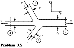
Подпись: Problem 3.5

Two jets of water with the same velocity impinge on one another, forming two other water jets, as shown. Assume a steady, inviscid flow of unit depth into the page. Also assume that all of the jets have a uniform flow. Calculate the jet width t2. Show the control surface used in the calculation and give the units of the answer.

3.6

Examples of the Art of Approximation Подпись: D, x
Examples of the Art of Approximation

A free-jet flow passes through a fixed cascade of turbine blades in a test stand at ambient pressure. Assume that the jet flow is inviscid (i. e., no losses) and steady and that the cascade turns the jet flow through a 45° angle. Calculate the lift and drag on the cascade. The flow may be taken as two-dimensional. Show the control volume used in the calculation and give the units for the answer.

Problem 3.6

3.7

Examples of the Art of Approximation

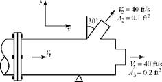
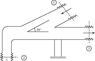
A liquid (p = 64.4 lbm/ft3) flows through a vent pipe and discharges to the atmosphere through two jets, as shown (p2 = p3 = ambient pressure). At Station 1, the vent pipe is bolted to the supply pipe by means of a flange. The static pressure at Station 1 is 12 psi above ambient pressure. Assume that the flow is steady and incompressible; ignore viscous and gravity effects. Show the control volume used in the calculation and give the units for the answer. Cal­culate the %-component of force on the coupling. Are the bolts in tension or compression?

3.8 A pipe receives a steady flow of liquid (p = 2 slug/ft3) through Station 1 and dis­charges into two other pipes at Stations 2 and 3. The volume flow rate through Station 2 is measured as 40 ft3/s. The pipe is restrained by a support, as shown. The couplings cannot support any load. Assume an inviscid one-dimensional incompressible flow. Ignore gravity effects and the weight of the pipe. Show the control volume used in the calculation and give the units for the answers. Find: (a) exit area A3

(b) у-component of force on the support: magnitude direction (up, down).

Examples of the Art of ApproximationPamb = 2,000 Psfa Pi = 3,000 psfa p2 = 2,100 psfa p3 = 1,000 psfa
A1 = 4 ft2

A2 = 0.8 ft2 V1 = 40 ft/s V3 = 60 ft/s

Problem 3.8

3.9 An air compressor takes in air at standard conditions (use 14.7 psia and 70°F) at a negligible velocity. The air is discharged at 115 psia and 125°F with a den­sity of 0.5 lbm/ft3. The mass flow rate out of the 0.5 ft2 discharge pipe is 12 lbm/s. If the compressor input horsepower is 800, find the magnitude and direction (in words) of the heat transfer to/from the compressor in units of BTU/s. Assume a steady flow. Draw a control surface for the calculation.

3.10 A steady flow of a gas passes into and out of a certain device. At the inlet, Station 1, T = 140°F and V1 = 20 ft/s. At the outlet, Station 2, T2 = 600°R and V2 = 30 ft/s. In passing through the device, 2 BTU/s of heat is extracted from the flowing medium and 4 HP of machine work is done on the flowing medium by an outside source. Calculate the mass flow rate through the device (slug/s). Ignore gravity effects and assume an inviscid flow. Draw a control surface for the calculation.

3.11 A steady flow of air at 5 slug/s passes through a certain device, entering at 100 ft/s and exiting at 200 ft/s. The entrance and exit static enthalpy of the air is the same, and 10 HP is supplied to the device. What amount of heat (BTU/s) is being added to (or subtracted from) the device? State the heat flux and direc­tion. Assume an inviscid flow and ignore gravity effects. Draw a control surface for the calculation.

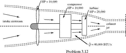
3.12 Consider the turboprop engine shown here. The intake and exhaust airflow rates are 100 lbm/s and the stagnation enthalpy of the entering air is 120 BTU/ lbm. The turbine, compressor, and propeller HP are 20,000, 10,000, and 10,000,

Examples of the Art of Approximation Examples of the Art of Approximation

respectively. The turbine drives the compressor and the propeller. Assume that the propeller does no work on the intake air; however, it does work on the air outside of the engine. Compute the jet stagnation enthalpy, hoj, assuming a uniform and steady flow. Use the suggested control volume and give the units for the answer. Then, work the problem again by doing it in two steps: the first step based on a control surface extending from upstream of the propeller to just downstream of the compressor, and the second step using a control sur­face extending from just downstream of the compressor to well downstream in the jet exhaust.

3.13 The velocity components u and v in a two-dimensional flow field are given by:

u = 4yt ft/s, v = 4xt ft/s,

where t is time. What is the time rate of change of the velocity vector V (i. e., the acceleration vector) for a fluid particle at x = 1 ft and y = 1 ft at time t = 1 second?

3.14 Consider a two-dimensional, incompressible, inviscid flow field given by:

V = (3x + 4t2 )i + (2x – 3y)j

a. What is the pressure gradient in the x-direction at a point (x = 2, y = 3) at t = 1/2 second? Assume the density of the flow to be 0.2 slug/ft3.

b. What is the convective acceleration of a particle in this flow field in the y-direction at (x, y,t) = (3,2,1)?

3.15

Examples of the Art of Approximation

The two-dimensional channel shown here has a linear variation of area between Stations 1 and 2 and has a steady volume flow rate of 20 ft3/s per unit width of channel. What is the convective acceleration of a fluid particle at x = 2 ft? Give the units for the answer.

3.16 Follow the same method used to derive Eq. 3.74 to determine the three-dimen­sional form of the differential-momentum equation.

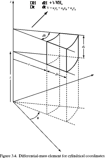
3.17 Using the vector form of the differential-momentum equation, deduce the three scalar components of the momentum equation in cylindrical coordinates (see Fig. 3.4).

3.18 Use the differential-element method to find the momentum equation in three­dimensional polar coordinates (see Fig. 3.4). Reduce to the two-dimensional form (i. e., no dependence on the z-coordinate) and compare to the results for Problem 3.17.

3.19 Use the differential-element method to find the momentum equation in three­dimensional spherical coordinates. Compare the results to the appropriate tables in the appendix.

REFERENCES AND SUGGESTED READING

Johnson, Richard W., The Handbook of Fluid Dynamics, CRC Press, LLC, 1998.

Kuethe, A. M., and Schetzer, J. D., Foundations of Aerodynamics, 2nd ed., John Wiley & Sons, New York, 1961.

Schlichting, Hermann, Boundary Layer Theory, 7th ed., McGraw-Hill Book Company, New York, 1979.

Serrin J., “Mathematical Principles of Classic Fluid Dynamics,” Flugge S. (ed.), Handbuch der Physik VIII/1, Springer-Verlag, Berlin, Heidelberg, New York, pp. 125-263, 1959.

Wilcox, David C., Basic Fluid Mechanics, Third Edition, DCW Industries, Inc., 2007.

Practical Methods of Problem Solution

Three approaches can be used to seek solutions to problems in aerodynamics of the type defined in this chapter as follows: [11]

It is important to understand that these methods always should be used in a mutually supportive manner. Too often, we see experimentalists who steadfastly insist that their (sometimes incorrect) experimental data are a better representation of reality than what is predicted by a theoretical model. Similarly, theorists who have grown too close to their favorite analysis may criticize the work of an experimen­talist as incorrect because it does not conform to their predictions. In contrast, those who practice the “black art” of CFD sometimes insist that their numerical com­putations represent the “correct” solution without checking whether all constraints and physical models used in the “black box” are truly appropriate.

Therefore, we start our study of aerodynamics with a strong bias in favor of methods that use application of simplifying assumptions. To make this work, we must be sure of the understanding of basic principles. This method has produced many of the most useful physical insights into the underlying behavior of aerodynamic flow fields. Never­theless, we frequently see situations in which such approximations fail. It is important to learn the appropriate strategies for addressing situations that do not readily yield to the familiar and comfortable assumptions that may have worked in a similar problem solved previously. It also is imperative to learn not to misuse simple theoretical results in cases in which the underlying simplifying assumptions may be violated.

It is shown by example how to determine when an experiment is necessary or when resort should be made to strictly numerical methods. Again, our approach is to show how all of the available techniques can be used in concert to produce a powerful, adaptable problem-solving strategy. Our first encounter with the need for experimental verification is in Chapter 5 as we learn about important applications of airfoil theory in wing design. The value of the theory in formulating experiments and the need for them in validating the theoretical predictions is an oft-repeated scenario.

A valuable application of computational methods is the ability to represent complex results in easily interpreted graphical form. Therefore, even in problems that can be well represented by an approximate analytical solution, numerical evalu­ation of the results and plotting them in graphical form is needed frequently. As part of the text, students are provided with an integrated set of numerical tools to use in the manner described. Numerical methods are used frequently to extend ana­lytical models that can be used only in their original form in simplified geometries, and so on.

Solution Procedures

Now that we are confronted by an intimidating set of partial-differential equations and complex boundary conditions, it is appropriate to discuss strategies for finding solutions. One method that is doomed to fail is to mount a frontal attack in an attempt to find a general solution to the problem. The student has no doubt already noticed that considerable effort has gone into examining special cases for the gov­erning equations as set forth in the tables in this chapter. For example, equations pertaining to steady, incompressible, or inviscid flows are carefully worked out. It should be obvious that our intention is to approach each problem from the stand­point of which simplifications can be made to reduce it to the most understandable and mathematically tractable form. In many cases, this results in a problem that can be solved fairly easily even without recourse to numerical means. Some of the most elegant and useful solutions were created using this approach.

We call this process the art of approximation. It was practiced in the past by the most innovative workers in aeronautics, and the various solutions are named after their creators. Confronted by the difficult nonlinear equations we now have derived, these investigators carefully determined where simplifying assumptions could be used to make the problem mathematically tractable. Students of these remarkable indi­viduals were required to learn this approach and often went on to improve the results or to create new methods of their own. As students study this textbook, they are pre­sented with numerous examples that show how this approach can be used to bring about extraordinary physical insight, as well as practical solutions, to difficult problems.

Many types of approximations can be introduced. These may take the form of appropriate physical assumptions such as the flow being incompressible or inviscid. They also may be based on linearization techniques such as those used in supersonic small-disturbance theory. These methods of approximation all receive careful atten­tion throughout the book.

Unfortunately, the analytical approach is not used as often at present as it was in the past. Some aerodynamicists believe that all of the “simple results have already been deduced.” Too often, we observe a tendency—when confronted by a diffi­cult aerodynamics problem—for an investigator to go directly to an experimental approach, or to what is equivalent to an experiment—the numerical solution by means of computational methods such as CFD. The latter approach is based on the ready availability of powerful and fast digital computers that can solve complex sets of differential equations (usually written by representing derivatives in an algebraic difference form) by iterative methods. In effect, this replaces the problem formu­lation by a general-purpose “black box.” In some complex situations, this is the only approach that can lead to the necessary information. However, it is important to understand that nothing can take the place of a thorough physical understanding of a problem. Therefore, it is of the utmost importance to practice solving problems in an approximate way by applying a set of appropriate simplifying assumptions. Then, even if the final solution requires relaxing some of those assumptions, and a brute – force numerical attack cannot be avoided, the means to check the numerical compu­tations are available. Many costly errors have been made because this principle was not clearly understood. Therefore, it is a major goal of this textbook to help students develop a thorough understanding of the available methods of solution, their rela­tive value in typical real-life situations, and their relationships to one another.

Boundary Conditions

Before further discussion of aerodynamic problem solving, it is important to realize that problem formulation requires a careful mathematical statement of the boundary conditions in addition to the set of governing differential equations that occupies much of our attention in this chapter. This section is a brief discussion of

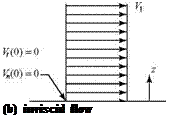
Подпись: (b) inviscid flow
Boundary Conditions

Figure 3.5. Wall boundary conditions for viscous and inviscid-flow models.

key features of aerodynamic boundary conditions, which must always be considered when applying the equations in particular applications.

The set of defining equations that must be solved is the same for many diverse problems in aerodynamics. The mathematical solution that correctly describes a specific problem is obtained by applying the appropriate boundary conditions. Boundary conditions represent physical constraints that the solution must obey; they usually involve the physical behavior of the flow and the particular geometry of the problem.

As observed in subsequent chapters, a primary boundary condition is one that specifies what the flow must do at the surface of an object in the flow or on sur­faces bounding the flow field. In a viscous-flow model, the boundary condition is that there is no slip at the surface—that is, the viscous flow adheres to the surface (see Chapter 2), so that both the normal and the tangential velocity components are zero at the surface. Of course, the normal velocity may not be zero if the surface is porous with fluid entering the region of interest through the boundary.

In an inviscid-flow model, only the tangency boundary condition can be invoked, which states that the flow must be everywhere parallel to the body surface or, equiv­alently, that there can be no velocity component perpendicular to a solid surface. Thus, in the inviscid-flow model, the normal component of velocity is zero at the surface but the tangential component is not! These two situations are contrasted in Fig. 3.5. Other types of boundary conditions may be encountered—for example, if mass transfer through a porous body surface forms part of the flow-field boundary.

Properties of the Defining Equations

The following observations are made concerning the equations that are derived in this chapter. We assume for now that only reversible thermodynamic processes are involved in the main part of the flow field of interest. If this is not so, additional equations may be required. For example, if it is required to study flow regions in which there are rapid changes in temperature, density, and pressure (e. g., within shock waves in compressible flow), then it may be necessary to supplement the equations already derived with an additional one containing consequences of the Second Law of Thermodynamics (Eq. 3.13). It may be necessary to include an additional variable like the entropy, s, to properly represent such situations. Simi­larly, there are cases in which noninertial control volumes and angular-momentum effects may be important. Because this does not happen often in this textbook, we propose to introduce such complexities only where they are necessary. If students have studied the material carefully, they will see that all of the mathematical tech­niques were presented to enable them to easily write any additional equations that may be necessary.

With this in mind, the problems we treat have the following characteristics from a mathematical point of view:

1. Six conservation equations—continuity (one), momentum (three), energy (one), and the equation of state (one)—provide the necessary set of equations to solve for the six unknowns of a general flow field—namely, u, v, w, p, p, and T, where u, v, and w can be replaced by any three orthogonal velocity components appro­priate to the coordinate system most convenient to the geometry of the problem.

2. The integral conservation equations are useful mainly when the flow is steady. For unsteady flow, evaluation of the volume integral in the equations requires detailed knowledge of the physical properties of the fluid inside the control volume.

3. Even without the considerable complication of including viscous forces and thermal-conductivity effects, the general solution of the complete differential – conservation equations is a formidable task. In fact, it is usually pointed out that general solutions do not exist because solution of a set of nonlinear par­tial-differential equations is required. Notice that several nonlinear terms are present; in particular, the convective acceleration terms are nonlinear. For

example, quantities such as udu appear that involve products of the variables

dx

and their derivatives. The mathematical consequence is that there exist no general solutions of the complete set of equations. Analytical solutions require sets of assumptions that usually lead to some form of linearization. Much of this book is devoted to devising useful solutions of this type.

Comments Regarding the Total Derivative

The total derivative appears naturally in many places in the differential analysis of fluid motion. Examine the general continuity equation, Eq. 3.50. By expanding the divergence term using the appropriate vector identity, we find that:

dp + V.(pV) = dp + V. Vp+pV V = 0; (3.75)

dt dt

therefore, the differential-continuity equation can be expressed in terms of the total rate of change of the density:

D + pV V = 0. (3.76)

Thus, the Eulerian derivative D/Dt applies to changes in other properties of the moving fluid and has the same physical interpretation we attached to its use with

Comments Regarding the Total Derivative Подпись: (3.77)

the acceleration of the fluid. The rate of change of any scalar property of the moving fluid particle is composed of an unsteady part and a convective part, so that:

where H represents any scalar property of the field such as pressure, p; density, p; and temperature, T. Only when the property being differentiated is a vector, such as the velocity, V, is it necessary to use the special form for the total derivative given in Eq. 3.73. For emphasis, note that it is not necessary to use the special form of the total derivative expressed in Eq. 3.73 if the derivative of a scalar variable is to be assumed. That is, VH is a proper vector operation. Then, Eq. 3.77 can be evaluated for any curvilinear coordinate system in explicit form.

The notation dV/dt sometimes is used to indicate the Eulerian derivative in a flow field that is independent of time (i. e., steady flow). In this situation, dV/dt only represents the convective acceleration.

Comments Regarding the Total Derivative

EXAMPLE 3.11 Given: An unsteady, incompressible, two-dimensional inviscid flow with no body forces has a flow field described by V = (2x + 4t2)i + (3x – 2y) j. Assume that the units of velocity are m/s.

Equating the terms associated with the unit vector j (i. e., the terms in the y-direction):

Подпись: Dv Dt + u + v _ 0 + (2 x + 4t2 )(3) + (3x – 2 y) (-2).

dt dx dy

Evaluating, Dv/Dt = 20 m/s2.

Appraisal: The Eulerian derivative depends on both space and time in this example.

The Differential Form of the Energy Equation

Comments Regarding the Total Derivative Comments Regarding the Total Derivative Comments Regarding the Total Derivative Comments Regarding the Total Derivative Подпись: (V-n) dS

Because the integral energy equation is a scalar equation, the derivation of the dif­ferential form parallels the development of the differential-continuity equation. Begin with the integral form of the energy equation, Eq. 3.42:

Подпись:(2int + ^2coND Wm+

-JJp(V. n)dS+ j]|p(V. b)dV ■

V ^ v J

Next:

1. Recall that the time derivative may be put inside the volume integral as previ­ously for the continuity equation.

2. Use the divergence theorem to change the two surface integrals to volume integrals.

3. Assume no machine work or chemical combustion and assume that potential energy changes are negligible.

4. Recognize that the heat-conduction term and the viscous-work-rate term each represent integrated effects over the entire surface of the fixed-control volume.

Подпись: (3.81)Thus, for example:

Qcond = Jj k д-dS = Jj Ы • VTdS = jjj k(V ■ VT)dV (3.78)

S S V

from the Fourier Law of heat conduction, where k is the thermal conductivity (taken here to be a constant property of the fluid) and dTIdn is the temperature gradient everywhere normal to the control surface. This is converted readily to control-volume form by means of the divergence theorem, as shown in the last term in Eq. 3.72. The work rate due to viscosity in Eq. 3.42 usually is represented by a mechanical or viscous dissipation function, Ф’. These viscous effects, as well as the heat conduction, are assumed negligible in most of the aerodynamics appli­cations that follow (i. e., the fluid often can be assumed to be inviscid and non­heat-conducting). This is clearly inappropriate in a hypersonic flow—for example, wherein there are high-temperature gradients and important viscous interactions. These two terms are evaluated in appropriate detail when needed.

Comments Regarding the Total Derivative Подпись: (3.79)

Incorporating all of the assumptions and manipulations denoted previously into Eq. 3.42, collecting all of the terms under a single-volume integral, and arguing that the integrand must be zero for an arbitrary control volume, it follows that:

Following the terminology used in development of the momentum equation, we refer to this equation as the conservation form of the energy equation. This means that it is the differential equivalent to the conservation of energy written in either system or integral control-volume form. In this form, the variable in the differ­ential equation is the energy (i. e., internal energy plus kinetic energy) rather than a single variable. As with the momentum equation, further manipulations can be made to write the equation so that only a single variable such as the internal energy or enthalpy appears in the derivatives; this is referred to as the primitiveform. Although Eq. 3.79 is not the most general case (we ignored internal heat gen­eration and radiation heat transfer), it exhibits most of the energy-balance inter­actions needed in aerodynamic applications. Equation 3.79 often is used in this (conservation) form to represent the energy balance in CFD machine solutions for complicated flow problems because experience shows that the numerical errors are smaller.

Comments Regarding the Total Derivative Comments Regarding the Total Derivative Подпись: (3.80)

Equation 3.79 simplifies under the assumptions of inviscid, adiabatic (i. e., no heat transfer) flow, and negligible body-force effects to:

This equation is important in the treatment of compressible flow.

Further manipulation of Eq. 3.79 leads to considerable simplification. Working with the second term on the left side and using the vector identity: V-

(л {

e +1V 2
2

Подпись: V ■ Подпись: e +|V2 IV Подпись: = pv ■ V Подпись: + Подпись: v • (pV), Подпись: (3.82)

(i. e., the divergence of the product of a scalar times a vector), we find:

d f 1 2

dt pl Є + 2 [10]

Подпись: dp d f 1 2 -rf + p—I e + -V2 dt dt ( 2 Подпись: (3.83)

where the vector in the identity equation (Eq. 3.81) was chosen to be pV because this combination (i. e., momentum per unit volume) appeared several times before. In fact, the last term in the resulting expression clearly is related to the continuity equation. To take advantage of this, expand the derivative in the first term in Eq. 3.79 to give:

Comments Regarding the Total Derivative
Подпись: e + - V 2 2

Then, adding Eqs. 3.82 and 3.83, we find:

f 1 > e +1V2

+v-

p

V

/

L 2 J

d f 1 2

dt pl e + 2 V

dp

dt

+ V – (pV)

Подпись: d dt1 Comments Regarding the Total Derivative Comments Regarding the Total Derivative Подпись: e +-V 2 2 Подпись: (3.84)

The first term on the right side of this expression must vanish so that the flow sat­isfies the continuity equation (Eq. 3.50). Then, remembering the definition of the total derivative, we write:

Comments Regarding the Total Derivative
Further simplifications result if we separate the kinetic and internal energy so that:

We see that

Подпись: D p -Dte+2 V2 l=p D+V.(-vp+p»+*v).

It also is useful to expand the term representing the rate of work done by the pressure force. Again, using the identity for expanding the divergence of the product of a vector times a scalar (Eq. 3.81), we find:

v • (pV) = V • (pV) = V. Vp + pV. v.

Inserting the several expanded terms into the energy equation, Eq. 3.79, we find that the body-force term from the momentum equation cancels what appears on the left side of Eq. 3.79. Part of the term involving the pressure also is canceled, leaving:

Подпись: (3.85)Подпись: pDe

—- + pV • V = kV2T + Ф, Dt

where the work-rate term involving the viscous force, V • fv, was incorporated in the viscous-dissipation function, Ф = Ф’ – V • fv. Equation 3.85 is the primi­tive variable form of the complete energy-balance equation. The only terms not displayed here are those representing the effect of internal heat generation (e. g., by combustion) and radiation heat transfer. It also must be remarked that the conduction-heat-transfer term was written here for the case of constant heat conduction, k. There are cases in which this assumption may be inappropriate. Because k may depend on the temperature, its variation with position may affect the outcome of calculations involving flows with strong temperature gradients. These matters as well as the dissipation function Ф are described in more detail in texts on high-speed flows, in which high temperatures and viscous effects may be quite important.

Table 3.7. Special forms of the differential energy equation

General energy equation (Eq. 3.85) (no 2

radiation heat transfer or internal p~pf + pV ‘ ^ — kV T + ф

heat generation)

Steady, adiabatic, inviscid flow ^ + V_ — h — Jconstant along

(Eq. 3.88) along streamlines 2 0 [streamlines

(no body forces or internal heat generation; no radiation heat transfer)

Подпись: V 2 h + ^ — h0 — Подпись:Steady, adiabatic, inviscid flow

(Eq. 3.88) with uniform temperature upstream (no body forces or internal heat generation; no radiation heat transfer)

Comments Regarding the Total Derivative Подпись: (3.86)
Подпись: D P Dt

There are many useful special forms of the energy equation; those most useful are summarized in Table 3.7. The so-called steady-flow form of the energy equation shown in the table can be deduced by rewriting Eq. 3.79 in primitive form by means of Eq. 3.84. Then,

Подпись: V ■ (pV) — V Подпись: -pv Подпись: — pV • V Подпись: + pV-(pV),

which is valid for inviscid, adiabatic flow with negligible body forces. The divergence term can be expanded by means of the vector identity, Eq. 3.78. We find:

Подпись: D P Dt Подпись: e +1V2 + p 2 P Подпись: — 0. Подпись: (3.87)

and if the flow is steady, the last term vanishes. The first term on the right side is the density times the total derivative (assuming steady flow) of p/p. Then, the two total derivative terms can be combined to give:

Because the total (Eulerian) derivative applies to a fluid particle moving with the fluid and the flow is steady, Eq. 3.87 indicates that the combination of terms:

e +1V2 + P 2 P

is constant along a streamline. Notice the appearance of the familiar thermodynamic property, h, the specific enthalpy:

h = e + — = e + pv,

P

where v is the specific volume. The energy equation, Eq. 3.87, often is written in terms of the enthalpy in place of the internal energy in thermodynamics problems involving fluid motion. Discussions related to the flow work and its connection to the pv combination are found in any good basic thermodynamics textbook, and are not included here.

It follows from Eq. 3.87 that the quantity:

, V2 h + T

is constant along a streamline—that is, along the path of the particle through the steady flow field. Evaluating the constant at a stagnation point where the velocity is zero and the flow was brought to rest adiabatically:

V2

h+ — = h,, (3.88)

where h is the static enthalpy, V is the magnitude of the local velocity vector, and h0 is the stagnation enthalpy. Equation 3.85 states that the stagnation enthalpy is con­stant along a streamline. If the flow from upstream infinity is uniform (i. e., all of the upstream flow has a constant temperature, which is the usual case), then the constant in Eq. 3.85 (i. e. the stagnation enthalpy) is the same everywhere in the flow field.

The energy equation of Eq. 3.85 is the simplest form of the conservation of energy principle because it is an algebraic equation. It is convenient to use this form instead of a differential equation when the assumptions for a particular problem allow it. Thus, if the flow is steady, adiabatic, inviscid, non-heat-conducting, and experiences no body forces, then Eq. 3.85 is all that is needed to ensure that energy conservation is accounted for properly.

If the random kinetic energy, e, is constant along a streamline, then:

1 2 P

—V + — = constant.

2 P

If the flow is also incompressible, then the density is constant and we find:

1 TT-2

2 pV +p = constant.

This is the famous Bernoulli Equation, which has considerable practical value because it directly relates changes in velocity to the local pressure. The derivation just presented is not displayed often because it does not adequately illuminate all of the underlying assumptions. It is considered better to derive it as a special form of the momentum balance, and we discuss it from that point of view in the next chapter.