Category BASIC AERODYNAMICS

Superposition of Uniform Flow and a Source Flow

Superposition of Uniform Flow and a Source Flow Подпись: 1 - Подпись: x Подпись: (7.35)

Similar to two-dimensional, planar flow (see Chapter 4), it may be shown by sub­stitution that the stream functions described by Eqs. 7.27 and 7.34 are both solu­tions of the defining equation for the stream function in axisymmetric flow, Eq. 7.23. Furthermore, because Eq. 7.23 is a linear equation, the sum of these two solu­tions is also a solution. In particular, the streamline у = 0 is the body surface with a stagnation point. Thus, a valid stream function for axisymmetric flow is given by:

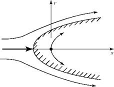
Taking an arbitrary but fixed value of the source strength, Л, and the freestream velocity, VTC, the resulting streamlines may be found by taking various values of у = constant and finding pairs of points (x, r) that satisfy Eq. 7.35. The result is shown in Fig. 7.9.

The flow field is seen to represent the axisymmetric flow over an open – ended body of revolution at zero angle of attack. Figure 7.9 appears the same for any (x, r) plane; thus, for any angle 0 in cylindrical coordinates. Notice that the stagnation point is upstream of the origin of coordinates, as expected. The fineness of the body of revolution may be altered by changing the values of Л and/or VTC.

Figure 7.9. Superposition of a three­dimensional source and uniform flow.

Superposition of Uniform Flow and a Source FlowThe velocity components ux and ur at any point in the flow field may be evaluated by using Eq. 7.35 in Eq. 7.20.

7.2 Flow Past a Rankine Body

Superposition of Uniform Flow and a Source Flow Подпись: (7.36)

The superposition in Section 7.8 may be extended by combining a uni­form axial flow with a three-dimensional source and sink of equal strengths and located a distance, a, upstream and downstream of the origin, respec­tively. For this axisymmetric flow, the equation of the streamlines is given in Karamcheti, 1967 as:

Superposition of Uniform Flow and a Source Flow

The resulting body shape in axisymmetric flow is a body of revolution called a Rankine body. The two-dimensional, planar-flow counterpart of this body is the Rankine oval. The shape of the two bodies and the streamlines associated with them are illustrated in Fig. 7.10.

Elementary Solutions for the Stream Function in Axisymmetric Flow

We now develop solutions for axisymmetric flow analogous to those described in Chapter 4.

Uniform Flow

Elementary Solutions for the Stream Function in Axisymmetric Flow Elementary Solutions for the Stream Function in Axisymmetric Flow

Consider a uniform flow, VTC, in the x-direction in cylindrical coordinates. Then, from Eq. 7.20:

u =-1 dv = -1 f'(x) = 0 =>/( x) = constant.

r d x r

Arbitrarily setting у = 0 at r = 0 (i. e., along the x-axis), the stream function for uni­form flow is given by:

V r2

V = ^- (7.27)

As expected, lines of constant stream function (i. e., streamlines) are parallel to the x-axis. Recall from Chapter 4 that each streamline may be assigned a value corre­sponding to the volume (or mass) flux between it and a reference streamline. For planar, two-dimensional flow, у(x, y)~y, Ду(x, y) = Ay, and equal increments in mass flux are represented by straight lines equally spaced, as shown in Fig. 7.7a. For axisymmetric flow, equal increments in mass flux again are represented by straight lines parallel to the axis of symmetry, but these lines are not equally spaced in the x-r plane because Ду(*, r) = Ar2. Thus, for axisymmetric flow, lines of constant incre­ment in stream function become closer together as the distance, r, from the axis of symmetry increases, as illustrated in Fig. 7.7b.

Source Flow

Подпись: x

Подпись: X

Consider a three-dimensional source at the origin of coordinates in three-space. One particular radial streamline from the source passes through any arbitrary point P(x, r) in any plane containing the x-axis and making an angle 9 with the у-axis, as shown in Fig. 7.8a. Now, we focus on one particular (x, r) plane (Fig. 7.8b) and recognize that

Figure 7.7. Constant increment in stream function, freestream flow.

Elementary Solutions for the Stream Function in Axisymmetric Flow

Figure 7.8. Three-dimensional source flow in axial plane of symmetry.

because of the symmetry of the source flow field, the flow behavior in any such plane is independent of ю—that is, the source flow has axial (as well as spherical) symmetry.

Elementary Solutions for the Stream Function in Axisymmetric Flow Подпись: (7.28)

In Fig. 7.8b, is the magnitude of the radial velocity at the point (x, r) due to a three-dimensional source at the origin of coordinates. From Eq. 7.25 this may be written as:

where K is a constant describing the source strength:

K = Л,

4 n

and L is the distance from the source to the point in question. Then, from Fig. 7.8b:

Elementary Solutions for the Stream Function in Axisymmetric Flow

L = 4×2 + r 2

Elementary Solutions for the Stream Function in Axisymmetric Flow Elementary Solutions for the Stream Function in Axisymmetric Flow

Now, we take the derivative of Eq. 7.30 with respect to x, which yields:

which means that f(x) is a constant. Reflecting this in Eq. 7.30 and again setting у = 0 along the x-axis (r = 0), it follows that:

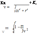
f (x) = , Kx = K = constant. six2 + 0

Подпись: or, because, K = Л /4 n Elementary Solutions for the Stream Function in Axisymmetric Flow Подпись: (7.34)

Thus,

Eq. 7.34 represents the equation for the streamlines (у = constant) in any down­stream axial plane of symmetry due to the flow from a three-dimensional source at the origin of coordinates.

Incompressible Flow around a Sphere

The three-dimensional point-source flow described herein can be extended to the representation of a three-dimensional doublet by superposing a source-sink pair similarly to the analysis detailed for two-dimensional, planar, incompressible flow in Chapter 4. Superposing uniform flow and a doublet at the origin with its axis parallel to the freestream leads to the solution for the flow around a sphere (see Anderson, 1991 and Karamcheti, 1967). The radius of the sphere is given by:

Подпись:о Y/3

й) (7’26)

where о is the doublet strength.

In Chapter 4, a two-dimensional, planar, flow field generated by the superposi­tion of a doublet and a uniform flow yielded the flow over a right-circular cylinder placed normal to the flow. The superposition of a three-dimensional doublet and a uniform flow gives the flow around a sphere. Both the radius of the cylinder and the radius of the sphere depend on the doublet strength. However, the radius of the cylinder varies as the doublet strength to the one-half power, whereas the radius of the sphere varies as the doublet strength to the one-third power.

According to the inviscid-flow model, the flow field about the right cylinder with its axis placed normal to the flow and also about the sphere is symmet­rical fore and aft, meaning that there is a stagnation point on both the upstream and downstream surfaces of the bodies along the flow axis of symmetry. Bound­ary-layer separation profoundly influences the flow field on the downstream side of both the cylinder and the sphere in the case of a real (i. e., viscous) flow situation.

The maximum velocity on the surface of both of these bodies occurs 90° in polar angle away from the two stagnation points (i. e., at the top and bottom). The results are, for the same radius:

cylinder: Vmax = 2.0V». sphere: Vmax = 1.5V».

Thus, the freestream does not accelerate to as high a velocity (or to as low a static pressure) around the surface of the sphere as it does around the surface of the right-circular cylinder of the same radius. This is evidence of a three-dimensional relief effect. The two-dimensional flow approaching a right-circular cylinder placed normal to the flow must split and pass either above or below the body. In the three­dimensional case, the flow passes around the sphere. Thus, the sphere causes less of a disturbance in a flow than the cylinder if both bodies are of the same radius. This same relief effect is observed when comparing supersonic flow around a two­dimensional wedge and an axisymmetric cone as developed in tests on compressible gas dynamics.

Three-Dimensional Point Source at the Origin of Coordinates

The point source referred to herein is a true point source in that flow exits from a point radially in all directions in three-space. The point source previously discussed in two-dimensional flow (see Chapter 5) is actually the cross section of a line source of infinite length that is perpendicular to the two-dimensional plane under study. Recall that source flow also is radial in two-dimensional, planar flow.

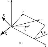
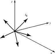
Consider a point source at the origin of a three-dimensional, Cartesian – coordinate system, as shown in Fig. 7.5.

Figure 7.5. Source flow at the origin.

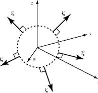
Three-Dimensional Point Source at the Origin of CoordinatesBy definition, the flow is purely radial, with a velocity given by Vs. We consider a fixed spherical control volume surrounding the origin of coordinates, with the center of the sphere at the origin (Fig. 7.6). Then, we make a calculation for the mass flux through the surface of the control volume. Recall that the surface area of a sphere of radius a is given by 4na2.

We let Л represent the volume flow out of the point source per unit time. Because the source flow is purely radial, the outflow velocity vector is always perpendicular to the spherical control surface and has a constant magnitude over the surface. Thus, the mass flow rate out of the source is:

m = рЛ = pjjV. ndS = pVs jjdS = pVs (4na2). (7.24)

Solving for Vs gives:

Подпись: (7.25)V = —Л-.

s 4na2

Contrast this result with the result previously obtained for a two-dimensional point source (i. e., corresponding to the radial flow through a cylindrical control volume with a line source along the axis of the cylinder). In the two-dimensional case, the radial-source velocity varies inversely as the radial distance from the source; in

Three-Dimensional Point Source at the Origin of CoordinatesFigure 7.6. Mass flux through fixed control volume.

the three-dimensional case, the radial-source velocity varies inversely as the square of the radial distance from the source.

Defining Equation for the Stream Function

Defining Equation for the Stream Function Подпись: (7.17)

Recall from Eq. 7.7 that the continuity equation for axisymmetric flow is:

which may be written as follows:

Подпись: (7.18)dux 1 d

U+r Tr(ru)=0

Now, we multiply Eq. 7.18 through by r. Because x and r are independent variables, the coefficient r in the first term may be included within the x-derivative, and Eq.

7.18 becomes:

Подпись:d(^x) + d(™r) = 0

dx dr

Eq. 7.19 is simply an alternate way of writing the continuity equation Eq. 7.18. Examination of Eq. 7.19 shows that it is satisfied by a scalar function (i. e., the stream function) such that:

Подпись: (7.20)dw dw

л = rux, ^ = – rur, dr x dx r

which defines the stream function, y(x, r) for axisymmetric flow. As in the two­dimensional, planar case, the derivative of the stream function yields a velocity component orthogonal to the derivative direction. Because y is related to the volume flow rate, a negative sign goes with the dy/dx expression in Eq. 7.20 so that the radial-velocity ur component has the correct sign to properly reflect continuity.

For an irrotational flow, the curl of the velocity vector (i. e., the vorticity) is zero. Applying the curl operator for axisymmetric flow, it follows that:

Подпись: 4 dr Defining Equation for the Stream Function(7.21)

Substituting the definition of the stream function, Eq. 7.20, into the irrotationality condition, Eq. 7.21, yields:

T f1T1 Vf f1 ? V 0. (7-22)

dr f r dr ) dx f r dx )

Finally, expanding Eq. 7.22 and rearranging:

d2 у d2 у 1д^_ о dx2 dr2 r dr

Eq. 7.23 is the defining equation for the stream function. If solutions for this equation can be found, then the velocity components can be determined by using Eq. 7.23, and the Bernoulli Equation provides the corresponding pressure distribution.

As in the two-dimensional, planar case (see Chapter 4), Eq. 7.23 is a linear equation so that elementary solutions may be superposed to generate solutions for more complex flows. As before, it is not necessary to solve Eq. 7.23 directly because useful elementary solutions for the stream function may be constructed, as demon­strated later.

Notice that the defining equation for the stream-function equation, Eq. 7.23, is not the Laplace’s Equation in the case of axisymmetric, incompressible, irro­tational flow. Compare Eq. 7.23 with Eq. 7.16; the sign before the third term is not the same. Contrast this with two-dimensional, planar, incompressible, irrota – tional flow, where the velocity potential and the stream function both satisfy the Laplace’s Equation.

Following the same procedure used in the planar case, elementary solutions for the stream function are constructed next and then superposed to generate more complex flow fields. The process begins with consideration of a three-dimensional point-source flow. A brief digression follows to examine the flow about a sphere in uniform flow. Then, the source flow and a uniform flow are superposed so as to construct the solution for a stream function that describes the flow around an axisymmetric body.

Defining Equation for the Velocity Potential

Подпись: V = ux ex + urer + ueee: Defining Equation for the Velocity Potential Подпись: (7.13)

This development parallels that for two-dimensional, planar flows in Chapter 4. If the flow is assumed to be irrotational, then the curl of the velocity vector is zero, Vx V = 0 . From this, it follows that a velocity potential, ф, exists such that V = Уф. Expanding the gradient operator in cylindrical coordinates, the velocity vector is given by:

Defining Equation for the Velocity Potential Подпись: Эф э! ’ Defining Equation for the Velocity Potential Подпись: Эф dr Подпись: (7.14)

from which it follows that in axisymmetric flow:

Подпись: д2ф + 1 _d_r дф dx2 r dr |_ dr Defining Equation for the Velocity Potential Подпись: (7.15)

For incompressible flow, the continuity equation is given by V • V = 0 so that for irro – tational flow V-(Vp) = V^ = 0. Writing the Laplacian operator in cylindrical coor­dinates, it follows that:

which for an axisymmetric flow reduces to:

Подпись: (7.16)Э2ф Э2ф і Эф —2 = 0:

dx2 dr2 r dr

where the velocity potential ф = ф (x, r ). Thus, as in the two-dimensional planar flow case, the velocity potential for axisymmetric flow satisfies the Laplace’s Equation. Because the Laplace’s Equation is linear, superposition techniques may be used to construct solutions.

The Momentum Equation

The Momentum Equation The Momentum Equation

As in the two-dimensional, planar case, the vector-momentum equation (Eq. 3.66) written for axisymmetric flow may be reduced to the Bernoulli Equation for the special case of incompressible, inviscid flow. To understand this, we expand Eq. 3.66 in cylindrical coordinates. Then, we simplify this vector equation by assuming axial symmetry. Next, we apply this vector equation along a streamline by taking the dot product of each term with an incremental streamline length ds = dxex + drer . Then, we appeal to the fact that a streamline is defined by:

Подпись: pd Подпись: 2 2 2 + 2 Подпись: + dp = 0.

and substitute this relationship as appropriate. The final result is:

Assuming incompressible flow, this may be integrated to give:

1 Подпись: (7.12)T/2

2 pV +p = constant,

which simply is Bernoulli’s Equation, as seen in Chapter 4 in Cartesian coordinates. The student should follow the procedure outlined to verify Eq. 7.12.

This result, Eq. 7.12, could have been deduced directly by realizing that the Ber­noulli Equation represents the momentum equation for any steady, inviscid, incom­pressible flow. Because the Bernoulli Equation is an algebraic equation containing two scalar quantities (i. e., velocity magnitude and pressure magnitude at a point) and because scalar quantities are independent of any coordinate system, then it is valid for any coordinate system.

Eq. 7.12 indicates that if the magnitude of the velocity at any point in an axisym- metric flow field can be found, then the static pressure at that point may be found directly. As in two-dimensional, planar flow, it is most convenient to introduce scalar functions to find the velocity components and, hence, the required velocity magnitude.

Axisymmetric Continuity and Momentum Equations

The study of the defining equations begins with the equations in vector form, as derived in Chapter 3. Thus, assuming zero body force and no viscous effects, then:

continuity: V • V = 0 (3.52)

momentum: pdjV + p(V • V)V + VP = 0 (3.66)

The notation to be used is illustrated in Fig. 7.2. The subscripts on the velocity com­ponents emphasize direction—they do not denote partial differentiation of the quantity, as used in some texts. The vector operations in Eqs. 3.52 and 3.66 now are expanded in cylindrical coordinates and then reduced by the assumption of axial symmetry. Because the flow is incompressible, the density, p, is assumed to be con­stant. We let the local velocity vector be given by:

V = ux ex + U er + ue ee, (7Л)

where ux, ur, and Ue are the velocity components in the cylindrical coordinate direc­tions and ex, er, and ee are the unit vectors in those directions (see Fig. 7.2).

The Continuity Equation

Axisymmetric Continuity and Momentum Equations

Writing the velocity vector and the divergence operator in cylindrical coordinate notation, Eq. 3.52 becomes:

Notice that the derivatives in the first set of brackets are taken relative to three two – term products in the second set. Thus, applying the chain rule to the d/dx derivative, for example:

(e ж)’ <“■ e ■( ‘■ tf) + ‘■ • (u Жт) (7.3)

A complete expansion of Eq. 7.2 thus contains 18 terms (the student should verify this). These terms fall into the following five different categories:

(1) Three terms contain a vector-dot product of unity, which then multiplies the deriv­ative of a velocity component relative to its own coordinate direction. For example:

3u. du„

p. p ___ x x

Єх Ex Э x Э x.

These three terms are nonzero and are written later.

(2) Six terms contain the derivative of a velocity component relative to another coordinate direction; for example, див/ dr. These six terms are nonzero, but they all appear as the coefficient of a unit vector, which then is dotted into a unit vector at right angles to itself, yielding zero. For example:

Подпись: = 0.3u0

dr

Thus, all of these terms drop out in the expansion of Eq. 7.2.

(3)

Axisymmetric Continuity and Momentum Equations

Three terms contain the derivative of a unit vector relative to its own coordinate direction; namely, 3ex / dx, dee/d0, and deTldr. Because the unit vectors are all of constant length, dej dx and dej dr are zero. The exception is Зе0/ Э0. Derivatives relative to 0 denote changes in direction. Analogous to (5), it may be shown that:

However, this term then is dotted with e0 in Eq. 7.2 so that the contribution of this term is zero as well.

(4) Five terms contain the derivative of a unit vector relative to another coordinate direction. These terms are:

dex der dex de0 d e0

d r ’ dx ’ d0 ’ dx ’ d r

All of these terms are zero because for a differential change in the magnitude of the denominator, there is no change in the magnitude or direction of the numerator unit vector.

(5) One term is an exception to Category (4) namely der / d 0, This term makes a non zero contribution to the equation. To see why, examine Fig. 7.3.

deL = lim (er)2 – (er)r = [(er>1 + B] – (er)

Axisymmetric Continuity and Momentum Equations Подпись: (7.4)

Э0 /vSo A0 A0

Подпись: z Подпись: 1
Axisymmetric Continuity and Momentum Equations
Подпись: B
Подпись: er
Подпись: Figure 7.3. Rate of change of unit vector.

У

Axisymmetric Continuity and Momentum Equations Подпись: Э0 Подпись: 1 u = ~r e0 'Ke0] = -f Подпись: (7.5)

When introduced into Eq. 7.2 the term containing this derivative then becomes:

Axisymmetric Continuity and Momentum Equations Подпись: (7.6)

Thus, Eq. 7.2 contains four nonzero scalar terms and the continuity equation in cylin­drical coordinates becomes:

Continuity Equation—Incompressible Flow—Cylindrical Coordinates

Setting д/д0 = 0 to reduce Eq. (7.6) to axisymmetric flow:

Подпись:Подпись: = 0.Axisymmetric Continuity and Momentum Equations(7.7)

Continuity Equation—Axisymmetric Incompressible Flow

The continuity equation, Eq. 7.7, is sometimes written in a more convenient form (see Eq. 7.18). The student should expand Eq. 7.2, examine each term, and then verify Eq. 7.7.

Now, we contrast the continuity equation in cylindrical coordinates, Eq. 7.7, with the continuity equation in two-dimensional Cartesian coordinates obtained by expanding Eq. 3.52; namely:

dU + dt = 0, (7.8)

о x d z

where u and w are the velocity components in the x and z directions, respec­tively. The presence of the additional term in the axisymmetric case leads to important differences between two-dimensional planar and axisymmetric prob­lems even though each problem is a function of only two independent variables. This is equally true for a compressible flow.

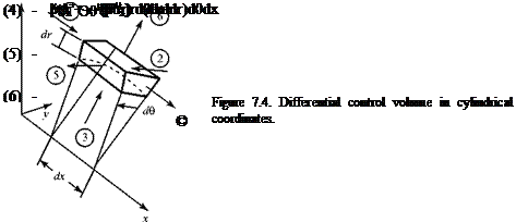
To verify the presence of this extra term, we rederive the continuity equation for the axisymmetric case by applying the Conservation of Mass principle to a fixed control volume of differential size. The flow is assumed to be steady but compress­ible for later use. The resulting equation then is simplified so as to describe incom­pressible flow. (Fig. 7.4).

The mass flux in through faces 1, 2, and 3 is:

(1) pux(rd0dr)

(2) pu0(dxdr)

(3) pur(rd0dx)

Axisymmetric Continuity and Momentum Equations

and the mass flux out through faces 4, 5, and 6 is:

Terms (2) and (5) are equal in axisymmetric flow because there is no change in flow properties relative to the angle 0 when axial symmetry is assumed (i. e., (p«e) = 0).

d e

Setting the sum of all of these six terms equal to zero by virtue of the conservation of mass for steady flow and then canceling Terms (2) and (5), as well as all like terms of opposite sign, the final result is:

—^(pux)rdxdrd0 – purdrdedx – r-^-(pur) – pdr2d0dx = 0. (7.9)

dr dr dr

The last term in this equation is of higher order than the other terms because it contains a product of differential magnitudes to the fourth power, whereas the three other terms in the equation contain only products of these quantities to the third power. Thus, the last term may be considered negligible (i. e., one order smaller) compared to the other terms in the equation in the limit as dx, dr, and d0 become very small. Recognizing this and then dividing by the common coefficient (i. e., – dxdrde), Eq. 7.9 becomes:

r dx(p ux>+pur+r d0(pur) = ^ (710)

Axisymmetric Continuity and Momentum Equations Подпись: (7.11)

which is valid for steady, compressible, axisymmetric flow. Finally, assuming p = con­stant, dividing by r, and rearranging:

Notice that Eq. 7.11 obtained by the application of the Conservation of Mass physical concept for an axially symmetric flow, is identical to Eq. 7.7 obtained by

expanding the vector formulation of the general Conservation of Mass equation (Eq. 3.52) for incompressible flow in cylindrical coordinates and then assuming axial symmetry.
Axisymmetric, Incompressible Flow around a Body of Revolution

7.1 Introduction

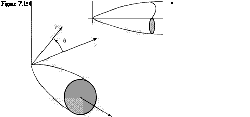
The flow considered in this chapter is assumed to be steady, incompressible, inviscid, and irrotational. The body immersed in the flow is assumed to be a body of rev­olution at zero angle of attack. An understanding of incompressible flow around bodies of revolution at zero or small angle of attack is important in several practical applications, including airships, aircraft and cruise-missile fuselages, submarine hulls, and torpedoes, as well as flows around aircraft engine nacelles and inlets. This type of flow problem is best handled in cylindrical coordinates (x, r), as shown in Fig. 7.1. Recall that r and 0 lie in the y-z plane.

Because the flow fields discussed in this chapter are axisymmetric, the flow properties depend on only the axial distance x from the nose of the body (assumed to be at the origin in most cases) and the radial distance, r, away from this axis of symmetry. The flow properties are independent of the angle 0. As a result, we may examine the flow in any (x-r) plane because the flow in all such planes is identical due to the axial symmetry. It is convenient to develop the defining equations initially in cylindrical coordinates (i. e., dependence on x, r, and 0) and then to simplify them for axisymmetric flow (i. e., dependence on x, r only).

Although there are only two independent variables (x, r) in axisymmetric flow, there are significant differences between such flows and two-dimensional, planar flows with two independent variables (see Chapter 4). As discussed later, an impor­tant three-dimensional relief effect is present in axisymmetric flow that is absent in two-dimensional, planar flows.

This chapter begins with a derivation of the continuity equation in cylindrical coordinates, starting with the general continuity equation in three-dimensional vector form and using vector identities. Then, the derivation of the continuity equation is repeated from a physical approach using Conservation of Mass prin­ciples. An extra term appears in the continuity equation in cylindrical coordi­nates that is not present in the continuity equation for two-dimensional, planar flow. This extra term is significant in the results of this chapter. It is important that the student fully understand why this additional term is present; hence, the repetition.

Axisymmetric, Incompressible Flow around a Body of Revolution

The momentum equation for axisymmetric flow reduces to the Bernoulli Equation as in the case of Cartesian coordinates. For incompressible flow, the energy equation is not needed.

Following the derivations of the continuity and momentum equations, the defining equations for the velocity potential and the stream function are developed. The problem of axisymmetric flow around a body of revolution may be treated either analytically or numerically. An appeal to the superposition of elementary solutions for the stream function (as carried out for planar flow in Chapter 6) provides analytical solutions for the flow around axisymmetric bodies of varying geometries. Such analytical results lead to physical insights about the flow field, as well as serving as benchmarks for numerical solutions. After a discussion of analytical methods, the chapter addresses the subject of numerical solutions of the axisymmetric, incompressible flow problem. Panel methods similar to those described in Chapter 6 are considered, as well as numerical methods, which use a distribution of singularities on the body axis. These methods usually are accompanied by a coupled boundary-layer analysis of some type to be able to predict the frictional drag (due to viscous-shear stresses at the body surface) and the form drag (due to boundary-layer separation) of a body of revolution. Normally, there is no well-defined trailing edge so that no Kutta condition is imposed and there is no trailing-vortex wake. If the aft portion of a fuselage is swept up (e. g., Lockheed C-130), then trailing vortices are formed that must be accounted for in a mathematical model.

In addition to the numerical solution of the direct problem (i. e., For a given body shape, what is the pressure distribution and boundary-layer behavior?), an important practical problem in numerical analysis is centered on finding a minimum-drag body shape. This is important because body shapes represented by the body of revolution have a major role in the total drag produced by several types of flight vehicles. For example, in the case of an airship, Lutz, 1998, points out that the drag of the airship hull accounts for about 66 percent of the total airship drag. Dodbele et al. state that for a transport aircraft, the fuselage drag contributes about 48 percent of the total air­craft drag when a turbulent boundary layer is present on all surfaces of the aircraft.

This percentage changes dramatically when a laminar boundary layer is assumed to exist on the lifting surfaces of a vehicle. (Recall the discussion of laminar flow air­foils in Chapter 5.) If the boundary layer on the wing and tail surfaces can be kept laminar (i. e., low frictional drag), then the fuselage drag becomes responsible for up to 70 percent of the total vehicle drag. It follows that a major payoff is possible if a fuselage can be shaped so as to maintain a laminar boundary layer, with a resulting lower skin friction, over as large a region as possible while also avoiding boundary – layer separation farther aft. The discussion of numerical solutions for axisymmetric flows concludes with remarks on the numerical analysis of a complete aircraft shape.

Strakes and Canards

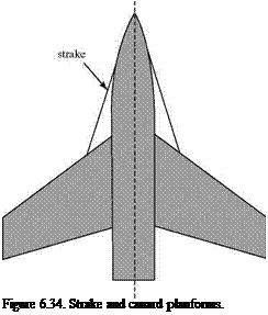
Strakes, also called leading-edge extensions are highly swept surfaces that are added to the wing at the wing root, shown in Fig. 6.34a. Their purpose is to cause leading – edge separation, resulting in a strong spiral vortex that sweeps back and over the wing, thereby providing vortex lift on the strake and added lift on the wing.

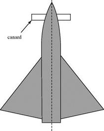
A canard, Fig. 6.34b is a separate miniature lifting surface placed forward of the main wing on an aircraft. Delta-wing aircraft must operate at a high angle of attack at low speeds (i. e., low dynamic pressure) to generate a sufficiently large lift coefficient to maintain flight. (The Concorde has a separate nose section that is angled down­ward for landing to improve pilot visibility.) At operational values of lift coefficient,

Strakes and Canards

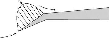
Figure 6.33. Leading-edge vortex flap.

Подпись: Figure 6.34. Strake and canard planforms.
Strakes and Canards

the delta-wing configuration exhibits a large nose-down pitching moment. The lifting canard supplies a nose-up pitching moment to counteract this behavior. A lifting canard also is useful for trim when flap deflection leads to the nose-down pitching moment of an aircraft. Careful canard design and placement can lead to beneficial mutual-interference effects between the canard and the main wing.