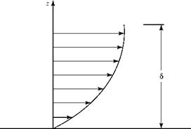
Category BASIC AERODYNAMICS

Boundary-Layer Displacement Thickness

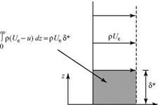
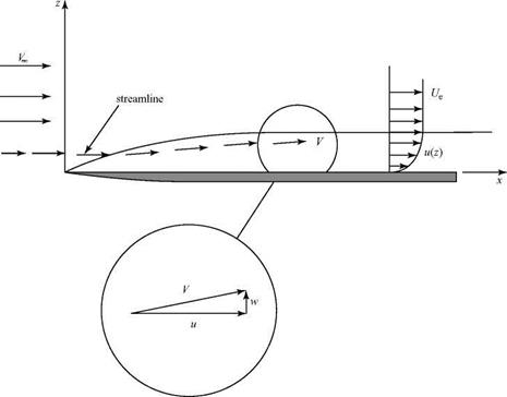
We consider an external flow streamline well away from the edge of a boundary layer growing on a flat plate, as depicted in Fig. 8.12. Because the flow within the boundary layer is moving slower than the freestream due to the action of vis­cosity, continuity requires that h2 > hi and the external streamline is displaced (slightly) from the horizontal. (The same effect was shown in Example 3.6 when considering the decelerated flow in the wake of an airfoil, with the control sur­face defined as a streamline.) The displacement thickness is a measure of how far the external flow streamlines are displaced away from the plate surface due to the presence of the boundary layer. The displacement thickness is defined by the expression:

In Eq. 8.69, the left side is set equal to the difference between the mass flux above the plate if there were no boundary layer, Term [2], and the mass flux above the plate with the boundary layer present, Term [3]. Thus, Term [1] represents the mass flux deficit (or defect) in the boundary layer caused by viscous action retarding the local-flow velocity.
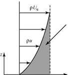
Подпись: Figure 8.13. Two velocity profiles with the same mass-flux deficit. Boundary-Layer Displacement Thickness Boundary-Layer Displacement Thickness

To interpret the definition, Eq. 8.70, physically, we consider Fig. 8.13. On the left is a Blasius velocity profile. On the right is a step profile that has u = 0 up to a height z = 5* and then an instantaneous change in velocity to the full external velocity Ue. Both profiles have the same mass-flow-rate (i. e., mass-flux) deficit. Thus, the mass-flux deficit due to the presence of the boundary layer, which causes the displacing of the flow streamlines outward, can be represented as the outward displacement of the solid surface by an amount 5*. A new effective body shape results, shown in Fig. 8.14, consisting of the flat plate plus an additional curved solid shape 5*(x).
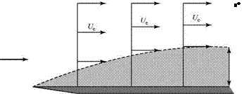
Boundary-Layer Displacement Thickness Подпись: Figure 8.14. Equivalent body shape in a viscous flow.

This discussion may be generalized to consider an airfoil in a viscous flow operating below the stall. The pressure distribution on the airfoil is calculated by using an inviscid-flow model. Then, the boundary-layer equations are solved for the velocity profile within the boundary layer (by methods discussed later) and, hence, S* may be evaluated from Eq. 8.70, which is valid for laminar or turbulent boundary-layer flow. This displacement thickness then is added to the airfoil shape (as S* was added to the plate) and a first iteration is carried out by calculating the pressure distribution on this equivalent airfoil shape using potential flow methods. A new S* follows and the process is repeated until a satisfactory convergence is achieved. Because S* nor­mally is small, only a few iterations are required.

s*-J|1 – U d-J|1 – f

2 г*

Подпись: 0 Подпись: e Подпись: 0 Подпись: f' Подпись: (8.71)

The displacement thickness for a laminar boundary layer on a flat plate can be evaluated from the Blasius solution. In this case, Eq. 8.70 becomes:

This integral can be evaluated numerically to yield:

Подпись: 1.7208(8.72)

where, again, x is the distance from the leading edge of the flat plate. This is a useful result in that it accounts for the presence of the boundary layer, and the expression is unique.

Boundary-Layer Momentum Thickness, 0

This parameter is defined in terms of the momentum deficit in the boundary layer rather than the mass deficit used in defining the displacement thickness. Thus,

Подпись: (8.73)pf/^ =JpuUedz – Jpu2dz,

00

Boundary-Layer Displacement Thickness Подпись: (8.74)

or, for incompressible flow:

In Eq. 8.73, Term [1] represents the momentum of flow within the boundary layer if the mass in the boundary layer has a velocity Ue, whereas Term [2] represents
the momentum of the boundary-layer flow if the boundary-layer mass has a velo­city u. Thus, by this definition, the momentum thickness, 0, represents a thickness of the freestream flow that has a momentum equal to the momentum deficit in the boundary layer. The quantity cannot be understood physically as easily as 5*, but it is useful in later discussions.

Подпись: 0 x Подпись: 0.664
Подпись: (8.75)

Evaluating Eq. 8.74 from the Blasius boundary-layer solution yields a unique expression:

5*

Подпись: 0 Подпись: fl1 Boundary-Layer Displacement Thickness Подпись: f—11 _ _u_ f и I 1 _ U
Подпись: 0
Подпись: 0 Ue
Подпись: dz.
Подпись: e
Подпись: (8.76)

The ratio of the displacement thickness to the momentum thickness of a boundary layer is called the shape factor, H; that is:

Shear Stress on the Wall, tw

Подпись: du xw = ^
Подпись: z = 0. Подпись: (8.77)

An important feature of the formation of a boundary layer on a surface is that there is a surface traction (i. e., a force parallel to the surface) in addition to the normal force due to the pressure. This can be an important source of drag on the body. Recall from Eq. 8.10 that in the boundary layer, the shear stress at any point in the flow is proportional to the rate at which the parallel velocity changes normal to the wall, du/dz. In particular, at a wall, the shear stress is:

This shear stress is a viscous (friction) force per unit area acting in a tangential direc­tion on the surface. Therefore, it is a local boundary-layer property, dependent on x. Differentiating the Blasius solution for u(z), we find:

Подпись: 0.332pUeBoundary-Layer Displacement Thickness(8.78)

The average shear stress on the wall over a length interval x = 0 to x = L then is given by:

Подпись: (8.79)= 7 fTwdx.

0

Boundary-Layer Displacement Thickness Boundary-Layer Displacement Thickness Подпись: (8.80)

Notice that the factor 1/L is required in the definition so that if an average value is assumed for tw over the interval, then the definition is consistent. Applying Eq. 8.79 to a Blasius profile:

where the Re number is formed with the length L. This average wall-shear stress acts on the surface area of a flat plate of length L (per unit width).

Friction Coefficient, Cf

The friction coefficient is a dimensionless expression for the wall shear stress, defined as:

Подпись: wT

(8.81) so that, for the Blasius profile:

~ _ (0.664)

Cf _~fr^ ■ (8.82)

V Rex

Boundary-Layer Displacement Thickness
The average friction coefficient for a surface over the length x _ 0 to x _ L is given for the Blasius profile by:

example 8.1 Given: A thin-wing model at a small angle of attack (approximate by a flat plate) has a chord length of 2 feet and a span of 10 feet. The wing is tested in an air stream of 100 ft/s at standard conditions. Assume a Blasius solu­tion for the wing boundary layer and assume two-dimensional flow over the entire wing span.

Required: Find the frictional drag force on the wing (both sides). Give the units of the answer.

Approach: Calculate the drag by first evaluating the average wall shear stress from Eq. 8.74 or Eq. 8.76.

Solution: Evaluating Eq. 8.76 using standard atmosphere values of p and v:

_ _ (0.664)(0.00238)(100)2 _ 0093lbf.

w V(2) (100) (0.0023 8)/ (3.72-10-7) ft2

An estimate of the viscous drag of the plate is then:

D = Tw (L)(width) x (2 sides) _ 40tw _ 3.72 lbf.

Appraisal: In calculating the drag, the average wall-shear stress must be used because the local stress is a “point” property. Check the units of the answer. Also, note that drag force is viscous stress times area. Accounting for the two sides of the wing is equivalent to stating that this is the frictional drag of the wing “wetted” area—that is, the total wing area exposed to the flow.

The experimental value of the local-friction coefficient for a flat-plate laminar boundary is about 0.001 at a Re number of 500,000. This experimental result and the prediction of Eq. 8.82 agree to within 6 percent. The experimental measurement is difficult (Liepmann and Dhawan, 1951), involving the direct measurement of the
shear force acting on a small section of the flat plate. When the turbulent boundary layer is discussed later in this chapter, it is found that the turbulent-velocity profile is fuller near the wall than the laminar profile; that is, near the wall, utorb > ulam. This implies that the wall shear stress and, hence, the frictional drag, is larger for a turbu­lent boundary layer than for a laminar boundary layer.

Boundary-Layer Thickness

Boundary-Layer Thickness Подпись: (8.68)

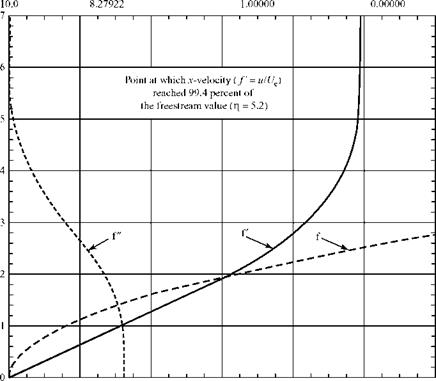
The boundary-layer thickness is defined previously (see Fig. 8.9) as the distance from the wall at which the velocity is “essentially” that of the external stream. The Blasius solution indicates that the boundary-layer velocity profile, u(z), approaches the velocity at the edge of the boundary layer, Ue, asymptotically. The boundary-layer thickness, then, may be defined precisely (but arbitrarily) as the distance from the surface at which the velocity, u, is an agreed-on percentage of the external flow velo­city. An often-used definition is f = u/Ue = 0.994 as the edge of the boundary layer (i. e., the velocity, u, in the boundary layer is 99.4 percent of the external freestream velocity, Ue), as shown in Fig. 8.11. Then, from Table 8.1:

Подпись: Rex Подпись: Ue x V

In this equation:

and the subscript x on the Re number signifies that it is to be based on a length x from the plate leading edge to the downstream station in question.

Eq. 8.68 provides an explicit expression for the magnitude of the boundary – layer thickness, but it is neither useful nor unique. For instance, if it were decided to define the magnitude of 5 as the value of z where the velocity ratio u/Ue is 0.999 (i. e., u is within 0.1 percent of the external velocity), then Table 8.1 indi­cates that the numerical factor in Eq. 8.51 is now about 6.01; there is a larger constant in the expression for 5 in Eq. (8.51). However, no matter which value of u/Ue that is chosen to define 5(x), it is always true that the boundary-layer thickness on a flat plate varies inversely as the square root of the Re number. Considering the additional linear dependence on x in the numerator, it can be seen that the thickness grows as the square root of the distance downstream from the leading edge.

Thus far, we have found the velocity profile for the flat-plate boundary layer and how the boundary layer grows. Now we define two other thickness properties of the boundary layer that have certain advantages over 5. In particular, they yield unique values for the thickness in any given situation.

Numerical Solution of the Blasius Equation by Finite Differences

Because computational methods are emphasized throughout this textbook, we now describe an alternate numerical approach to the flat-plate boundary-layer solution that introduces CFD methods. Of course, we cannot undertake an in-depth dis­cussion of all of the subtleties of these methods. However, the present problem rep­resents an excellent opportunity to introduce a powerful procedure for obtaining solutions to otherwise intractable boundary-value problems.

We introduce the subject with no pretense of completeness and let the interested student seek further. Here, we primarily are interested in applying an approximate solution procedure to a nonlinear, ordinary differential equation and using these results in our boundary-layer analysis. Thus, the subject is developed as it applies to the Blasius equation given by:
with boundary conditions:

m=f ‘(о)=o, r o-)=1

as before. For simplicity we introduce:

g = f’

so that the Blasius equation becomes:

О

II

bo

‘4-І

+

*

bo

<N

(8.56)

with boundary conditions given as:

f (0) = g(0) = 0, g(-) = 1.

(8.57)

In what follows, we attempt to represent the derivatives by their finite-difference equivalents. Only the derivative normal to the surface must be accounted for in this simple problem. In effect, the integration in the direction of the flat plate already was accomplished. That is, we are dealing only with an ordinary differential equation rather than the partial-differential equation that must be confronted in a more general problem. The point to remember is that the same approach could be applied in the case of more independent variables, which we do in later applications.

Note that Eq. 8.56 is linear in g. However, it is still a nonlinear equation and we set up an iterative solution procedure at selected points in the domain. Here, the domain is the boundary layer. Thus, we divide the domain into a set of discrete points and number them from 1 to N (with N being the number of points that we are using). We choose to place the first point on the wall and the last point at the edge of the boundary layer. The next step is to create an approximate solution method whereby we find the values of the variables at these points. We do so by using these values and Taylor-series expansions to replace the derivatives in the equation with finite differences.

We note from the general Taylor series for a function f(x) evaluated at a nearby point, x + Ax, that:

Ax2 At3 Ax4

f (x±Ax) = f'(x) + f'(x)Ax + f "(x)^2- ± f’"(x^3L + f ""(*) ± … (8.58)

Thus, in terms of our independent variable, n, we have:

f (n ± Ат|) = f ‘От) ± f"(4+Ато+f At ± f"’ От) +f "00 Af ± … (8.59)

Now, with An being the spacing between points in the domain, we can see that:

if

fi = f(n),

then

fi+1 = f(n + An),

(8.60)

and

i

p"

и

By adding or subtracting Eqs. 8.58 and 8.59, it is now possible to find the expressions:

Подпись: (8.61)f ‘(^=fi+12An-1 -1r’ w Af+0( ^3)

Numerical Solution of the Blasius Equation by Finite Differences

Numerical Solution of the Blasius Equation by Finite Differences

(8.62)


We note that the second and remaining terms on the right-hand side of Eqs. 8.61 and 8.62 are of much smaller size (small An and derivatives not too large) than the first and we choose to drop them. This gives an algebraic expression for the first and second derivatives.

Next, we apply Eqs. 8.61 and 8.62 to Eq. 8.56 for g(h). This results in:

Подпись: (8.63)gj+1 – 2gi + gi-1 + f gi+1~ gi-1 = 0 An2 f 2 An!

which is a second-order approximation to Eq. 8.56. Eq. 8.63 can be rewritten by collecting the coefficients of the different g’s to obtain:

or Cigi=1 + bigi + agi+1 = 0, (8.64)

where:

The subscript i now refers to the fact that Eq. 8.64 represents the equation arising from applying finite differencing to the Blasius equation at the ith grid point. Also notice that the coefficients are functions of f and, hence, vary throughout the domain.

We note that Eq. 8.64 is applicable to every point in the domain from i = 2 to i = N-1 (we already know the values at i = 1 and i = N; these are the boundary con­ditions). Thus, there are N-2 equations for the N-2 unknown values of g. (We address the unknown value of f after setting up a procedure for g.) Applying Eq. 8.64 at each point between i = 2 and i = N-1 yields a linear system of the following form:

. (8.65)

This shows how to calculate the N-2 values of g. We would be finished were it not for the fact that we have not yet found the fj’s. To do this, we recall that f and g are related through Eq. 8.57 and we can find the values of f once we have found gi by a simple numerical quadrature. However, we still need values for f to obtain the values of g from Eq. 8.65. Thus, we make an initial guess for the g’s and compute the fs from this guess. Once we have found new values of g, we then can recompute f. This iterative process repeats until the solution no longer changes.

When the solution no longer changes, we say that the process has converged. Generally, the way this is checked is to see whether the maximum change in one variable is no larger than a small number. We call this number the convergence cri­terion. In our process, we check for the maximum change in g to be no larger than some reasonably small number—say, |Agi |max < 10-6.

We now return to obtaining the values of /. Recall that f = g; hence:

Подпись: n 0 (8.66)

Because we only know g at discrete points, we must approximate this integral. We do this using the trapezoidal rule. Thus, Eq. 8.66 becomes:

і 1

fi = X 2(gj + gj-iX^j – Vi)- (8.67)

j = 2 2

The summation starts at 2, recalling that f is at the wall and has a value of zero. Now, we can set up the entire numerical procedure as follows:

1. Select N and the height of the domain (maximum value of h).

2. Make an initial guess for the value of g at the points in the domain (linear between the boundary values suffices).

3. Find values of / in the domain from Eq. 8.67.

4. Solve Eq. 8.65 for new values of gi in the domain.

5. Check whether the process converged.

6. If not converged, repeat from Step 3.

7.

Подпись: Program BLASIUS, a program on the website, implements this scheme. The student is invited to run this program now to explore the behavior of the boundary-layer numerical solution. The output is presented in graphical form showing the variation of / and its derivatives with n. The next section is a detailed description of the solution and its interpretation. In particular, it is important to determine the shearing stress and, hence, the drag force on the surface created by the viscous effects that lead to the presence of the boundary layer.

When converged, both g and/now are known at all points in the domain and the boundary-layer properties may be computed from them.

8.7 Results from the Solution of the Blasius Equation

Certain parameters describing the laminar boundary layer on a flat plate (i. e., zero pressure gradient) may be evaluated using the solution of the Blasius equation. The definitions of the parameters are valid for either a laminar or a turbulent boundary layer, with or without a pressure gradient. After the key parameters are defined, their values are expressed for a laminar boundary layer (i. e., Blasius profile) on a flat plate. Although the freestream flow is little disturbed by the
presence of the flat plate, the velocity at the outer edge of the boundary layer is denoted by Ue(x) rather than a constant value such as Vж implied in the flat-plate solution. This allows for later generalization. In particular, the former notation implies that the velocity outside the boundary layer is allowed to change in the x-direction as required by an imposed pressure gradient or as a result of curvature of the surface.

The z-Velocity Component in the Boundary Layer

Notice that although we have not required anything from the z–component of the momentum equation other than information regarding the pressure gradient normal to the surface, it does not mean that there is no velocity component in the z-direction. This is a misunderstood feature of boundary-layer theory. Because there is a momentum deficit near the surface (i. e., the flow speed in the parallel direction must decrease to zero to satisfy the no-slip requirement), the result is a velocity com­ponent normal to the surface. That it is required by continuity is seen easily because from the first of Eq. (8.37):

which shows that the normal velocity is zero at the surface (as is required by the solid-wall-boundary condition) and increases to a maximum as the edge of the boundary layer is approached. This result also shows that the normal velocity is very small because it is proportional to the square root of the product of the freestream velocity and the viscosity coefficient.

The z-Velocity Component in the Boundary Layer

Figure 8.12 shows the behavior of the flow near the leading edge of the plate and indicates the upward deflection of the streamlines resulting from the formation of the boundary layer.

The magnitude of the z-velocity decreases as distance along the plate increases; that is, the first term in Eq. 8.54 decreases as the inverse of the square root of x whereas the second term decreases faster because it is inversely dependent on x. Far down­stream, there is no normal velocity. Equation 8.54 also demonstrates a fault with the theoretical results. Notice that at the leading edge of the plate, the simple theory pre­dicts that the normal velocity must be infinite because x = 0 at that point. This is a result of failure of our assumptions regarding relative sizes of the various quantities in proximity to the leading edge. That is, the simplified equations do not hold there. This defect can be corrected by application of powerful singular-perturbation methods that are based on the simple analysis we used. It is beyond the scope of this book to discuss these so-called leading-edge corrections. It also is possible to resort to a com­plete two-dimensional, CFD numerical solution in which derivatives in both the x – and z-directions are represented with finite difference formulas. If care is taken to use a suf – ficently fine grid near the leading edge, the apparent mathematical difficulty (usually referred to as a singularity) can be resolved. The CFD solution method is introduced in the next subsection. However, it displays the same defect at the leading edge that we just discovered because it attempts to solve the simple Blasius equation rather than the complete two-dimensional, Navier-Stokes equations. In other words, the defect is in the simplified differential equation rather than in the method of solution.

Comparison of Theoretical Solution to Experimental Data

Подпись: <8.52)It is of interest at this point to compare the analytical solution to actual experi­mental data for the laminar boundary-layer results. The problem just solved may seem rather abstract because of the several stages required in its definition. It was necessary first to derive the basic equations describing the fluid dynamics. The equations then were modified using Prandtl’s physical insights to properly incor­porate the viscous terms. This led to stretching the coordinate normal to the wall and the introduction of the boundary-layer coordinate, n. A powerful mathemat­ical technique, the similarity method, then was used to find an analytical solution. After all of this manipulation of the problem, the student may wonder if there is anything left that properly represents reality. As usual, the answers can be found

Comparison of Theoretical Solution to Experimental Data

<D

a

1=

о

о


Comparison of Theoretical Solution to Experimental Data

0 0.2 0.4 0.6 0.8 1 1.2


Comparison of Theoretical Solution to Experimental Data

/ я f"

Figure 8.11a. Plots of the Blasius function, f, and its derivatives.

only by comparing analytical results to experimental measurements. This was done by many investigators, but a particularly careful set of measurements was carried out by Nikuradse in 1942 (See Thwaites, 1949). His measurements were made at five locations along the flat plate to study the effect of the Re number (in the range 1.1.105 < Re < 7.3.105) on the velocity profile. One item that he wanted to verify was the similarity of the velocity profiles. That is, the shape of the velocity distri­bution should be the same at any axial location. Figure 8.11b shows his measure­ments. The horizontal axis is the boundary-layer coordinate as we defined it in Eq. 8.46. The vertical axis in this plot is the value of the dimensionless x-velocity, f = u/Ue. There can be no question that the agreement between the Blasius flat – plate theory and the experimental data is virtually perfect. This should help to build the student’s confidence in the powerful mathematical methods introduced herein.

Application of the Similarity Method

The word similarity is used in several contexts throughout this book. There is a sig­nificant probability that the student is becoming confused from the frequent appear­ance of this terminology in seemingly different uses of the same word. Therefore, the several meanings are reviewed briefly, as follows:

1. Geometric Similarity. This describes two or more body shapes that are exact photographic images (i. e., enlargement or reduction) of one another.

2. Similarity Parameters. These are dimensionless quantities that can be deduced from dimensional-analysis considerations or from experiment—for example, the Mach number, Re number, and lift coefficient. These are especially useful in presenting results or when planning experiments.

3. Similarity Relationships. These are functional relationships between similarity parameters. They may be explicit when equation solutions may be found, or functional in form if the defining equation is difficult to solve, as in nonlinear – flow problems.

4. Dynamic Similarity. If two geometrically similar bodies are in two flows that have the same values of the pertinent similarity parameters, then the two flows are dynamically similar. The pertinent similarity parameters may be found by dimensional analysis or by writing the defining equations for that class of problem in nondimensional form. Similarity parameters appear as coefficients in the equations. For example, if the laminar boundary-layer equations for incompressible flow are written in nondimensional form, the only parameter that appears is the Re number. Hence, a known solution to the equations for one flow problem also is a solution (in nondimensional form) to a second flow problem, provided that the two flows have the same Re number. For com­pressible flow, additional pertinent similarity parameters usually are the Mach number, Prandtl number, and ratio of specific heats, y. Dynamically similar flows have equal-force coefficients.

5. Similarity Rules. Two flow problems can be called similar in the sense that they are related by a coordinate transformation connecting the two defining equations and the two sets of appropriate boundary conditions. Certain scale factors arise that relate to the pressure and force coefficients and the shape of the two bodies in the two flows.

6. Similarity Solutions. These are methods of solution in which mathematical advantage may be taken if the solution at one station in a flow is geometri­cally similar to solutions at other stations. For example, in certain boundary layers, the velocity profiles are of the same mathematical family. When this hap­pens, it becomes possible to construct a new independent variable—which is a
combination of the original dependent variables—such that the derivatives in the governing equation(s) all can be written as derivatives of this new indepen­dent variable. For two-dimensional, viscous-flow problems, partial-differential equations become ordinary differential equations when similar solutions are assumed. Similar solutions in viscous flow involve “self-similar” velocity profiles, meaning that the profiles collapse to a single curve when graphed in appropriate coordinates. An example is the velocity profile in the incompressible boundary layer growing along a flat plate.

7. Similitude. Two flow problems have similitude if they have identical defining equations and boundary conditions when written in dimensionless form.

It is in the context of the sixth meaning that we are working herein. Referring to Fig. 8.10, notice that we expect the flat-plate boundary layer to increase in thick­ness as the distance from the leading edge is increased. It is certainly plausible that the velocity distribution across this thickness would be “similar” at any station. We now examine the differential equations to see if this is a possible outcome, which is accomplished by checking whether the equation and the boundary conditions are unaffected by an affine transformation. Such a transformation is one in which a parameter—say, X—or its powers can be used to scale each variable without changing the form of the mathematical problem. That is, the problem is invariant to the transformation.

If the differential equation for the stream function (Eq. 8.40) and the four boundary conditions (Eq. 8.41) are transformed in this manner by setting:

y = Xy’

л n f

• x = X x (8.41)

z = Xm z’

Application of the Similarity Method Подпись: (8.42)

where the primes denote the “stretched” variables, we find that the problem is now governed by:

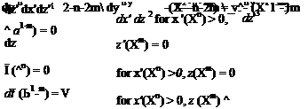
^(X1-m) = У for x'(Xn) = 0, z(Xm) > 0

I. dz ”

For a similarity solution to be available, it is necessary for all occurrences of the parameter X to disappear in the transformed equations. This is so only if:

Подпись: (8.43)X2-n-2m _ X^3m

and X1-m = 1.

Подпись: •Jx Подпись: Xz' Application of the Similarity Method Подпись: (8.44)

Notice that the boundary conditions requiring zero values are unaffected by the transformation. Therefore, for a similarity solution, it is necessary only that m = 1 and n = 2. Then, Eq. 8.43 reduces to the same set before the transformation. The real benefit from the transformation process begun here is that it suggests that we can combine the original independent variables such that the number of variables required in the problem can be reduced. For instance, the combination:

yields such a result. Notice that the new combined “length” variable does not have the dimensions of length but rather the square root of length. It is often better to work with dimensionless variables, so we seek to introduce appropriate scaling factors from the natural parameters in the problem to render the transformed problem in dimensionless form. The velocity of the uniform parallel flow outside the boundary layer, Ue = Vж can used as a reference velocity. Since there is no natural length scale of the sort present in the Couette and Poiseuille flows, it is necessry to use the parameters in the differential equation to form an equivalent reference length. Notice that the combination:

v [ft2/sec]

Ue ^ [ft/sec]

Подпись: n = Подпись: = z- Подпись: (8.45)

has the dimensions of length, so all the dimensional length variables like x and y or X and y can be rendered dimensionless by dividing by v/Ue. Therefore, if we replace x and y and X and y’ by their dimensionless equivalents in Eq. (8.45) we can define a dimensionless transformed coordinate, n as:

Подпись: f Подпись: y U_ 4~x |_Uev Подпись: y = Xy' = y' >Ue x JvUe xX2 x' VvUe xx'

Combining the original dependent variable, y, with the original independent vari­ables can result in a new dependent variable that is independent of the parameter X. Call the new (dimensionless) dependent variable f, which we assume will be a function only of the new single dependent variable n. To eliminate the X in the transformed stream function, we note that x = XV so х = 4ХЇХ and f can then be defined in dimensionless form as:

which satisfies the criterion that parameter X does not appear explicitly. The param­eters within the square brackets represent the dimensions of the stream function and the inverse square root of the characteristic length. Since f is dimensionless by definition, we can then write the (dimensional) stream function as:

Подпись: (8.46)y(*. ^ = 4vU*x ^(n)

The detailed steps we have shown here are not usually presented in undergraduate textbooks. What is often done is to introduce the results shown in Eqs. (8.46) and (8.47) as assumptions with little justification other than that “it works.” Although you may have trouble understanding fully the significance of the similarity trans­formation process in a single reading, you are invited to study the steps again when confronted in the future by problems that may require a similiarity solution.

Now, to see if this new set of variables represents any kind of an advantage, we attempt to rewrite Eqs. 8.40 and 8.41 in terms of n and f. Several derivatives must be evaluated, so we note first that:

Подпись: z U -f __n V 2x = ZK±X~ 2

dx V V dx

dn= —

dz V VX

Please keep in mind as we use these results that we are transforming the set of independent variables (x, z) to the new set of independent variables (x, n). Care must be taken in the differentiation process. The derivatives of any function with respect to the original variables must now be written as:

d^d+dpd_d n d

Подпись:dx dx cX dp cX 2 x dp

2^элА_ U_d_

dz dz dp V VX dp

Application of the Similarity Method Application of the Similarity Method Подпись: (8.48)

so that the derivatives needed in Eq. (8.40) are:

Application of the Similarity Method
The Blasius Flat Plate Boundary-Layer Equation

and after simplifying,

2 f"’ + ff "= 0 (8.49)

which is often called the Blasius boundary layer equation. The boundary conditions in like fashion simplify to

[ f ‘(0) = 0

{f (0) = 0 (8.50)

1 f'(~) = 1

since f is a function of n only. The original complex partial differential equation reduces to a simple (but nonlinear!) ordinary equation. Since Eq. 8.50 is nonlinear it is necessary to apply numerical methods for its solution. Another feature requiring special attention is that the boundary conditions must be satisfied at two widely separated locations (n = 0, and n = 0). This means that we must solve a two-point boundary value problem by numerical means. Many approaches have been devel­oped in the years since Blasius presented his Ph. D. thesis work. Many of these were developed before the ready availability of fast digital computers, so they necessarily employed a variety of mathematical strategems that are no longer needed and are therefore not discussed here. The problem can now readily be handled on your per­sonal computer or even a good programmable hand calculator.

For example, one can easily solve the problem using a simple fourth-order Runge-Kutta integrator and a simple shooting method to deal with the two-point boundary value features. Equation (8.50) is first broken down into three simul­taneous first-order ordinary differential equations. For example, one can write

where the first two equations simply define the derivatives of the variable f. Since there is no boundary condition on h, (equivalent to the second derivative of f with respect to n, then we can adjust this value until g = 1 at a large value of the indepen­dent variable n. Newton’s method or a similar technique can be used to adjust an initial guess for h at n = 0. It is not necessary to carry the integration to a large value of n. Experience shows that once a value of about 10 is reached, this is effectively infinite on the scale of n. The detailed calculation is left to the student in a problem at the end of this chapter.

Numerical results from this procedure are shown in Table 8.1 and Fig. 8.11a. Notice that in Fig. 8.11a, the plot for f versus h is a representation for the velocity distribution through the boundary layer if f is proportional to the x-velocity, as indi­cated in Eq. 8.47. That is, the x-velocity component through the layers is:

n

f

f ‘

f"

0.0

0.00000

0.00000

0.33206

0.5

0.04149

0.16589

0.33091

1.0

0.16557

0.32978

0.32301

1.5

0.37014

0.48679

0.30258

2.0

0.65003

0.62977

0.26675

2.5

0.99631

0.75126

0.21741

3.0

1.39681

0.84605

0.16136

3.5

1.83770

0.91304

0.10777

4.0

2.30575

0.95552

0.06423

4.5

2.79014

0.97952

0.03398

5.0

3.28328

0.99154

0.01591

5.5

3.78058

0.99688

0.00658

6.0

4.27963

0.99897

0.00240

6.5

4.77933

0.99970

0.00077

7.0

5.27925

0.99992

0.00022

7.5

5.77923

0.99998

0.00006

8.0

6.27922

1.00000

0.00001

8.5

6.77922

1.00000

0.00000

9.0

7.27922

1.00000

0.00000

9.5

7.77922

1.00000

0.00000

10.0

8.27922

1.00000

0.00000

Table 8.1. Function f and its derivatives

where Eq. 8.48 for the z-derivative is used. Thus, the solid curve in Fig. 8.11 is the famous Blasius laminar-velocity profile for a flat-plate boundary layer. Carefully measured velocity profiles show essentially exact agreement with the theoretical predictions from the Blasius analysis shown in Fig. 8.11a.

Incompressible Boundary-Layer Theory

We now carry out a detailed solution for one of the most important viscous-flow problems in aerodynamics—namely, the high-Re-number flow over a flat plate. The analytical technique demonstrated for the flat-plate problem is the key to under­standing a wide variety of other engineering solutions. Clearly, something special is needed to handle the nonlinear (i. e., convective acceleration) terms still present in the momentum balance. This means that the methods of differential-equation theory do not apply. Separation of variables and superposition are no longer appli­cable tools. A method of great utility in such situations is introduced, which often is called the similarity method.

By a flat plate, we mean a surface on which there is no impressed pressure. The governing equations are those shown in Eq. 8.37 without the pressure gradient in the x-direction. That is, both components of the pressure gradient are now zero:

du + dw dx dz

Подпись:du dw dzu

u— + w— = v—-.

dx dz dz2

Incompressible Boundary-Layer Theory Подпись: for x > 0, z = 0, and Подпись: (8.38)

This special case was first solved in 1907 by Blasius, a graduate student of Prandtl, at Gottingen University. A solution to Eq. 8.38 is sought that satisfies the no-slip requirement at the surface and matches the flow field at great distance from it. In mathematical form, we require that:

u = Ue(x) for x > 0, z ^ «= u = V^ for x = 0, z > 0.

A major difficulty in carrying out this solution is that the momentum equation is nonlinear. Students undoubtedly have noticed that the nonlinearity is associated with terms arising in the convective acceleration part of the momentum balance. Classical methods for solving partial-differential equations (e. g., a separation of variables) are not applicable in this problem. Also, we lose the ability to superimpose simple linear solutions in representing more complex cases, a technique exploited many times in preceding chapters. Therefore, we must approach this problem differently than in the more conventional situations that arose in the Couette and Poiseiulle flows and in the potential flow problems addressed previously; these were linear problems.

Incompressible Boundary-Layer Theory Incompressible Boundary-Layer Theory

A useful step is to reduce the number of dependent variables by using a stream function to represent the velocity field. The continuity equation is satisfied exactly if we write:

Modern computational techniques (i. e., CFD methods) are used routinely to solve nonlinear problems of this type. However, we want to demonstrate a powerful tech­nique that uses mathematical finesse rather than computational brute force to give the required answers. Recall that much physical insight can be gained by using this
approach in place of the “black-box” computations in difficult problems. The price of these benefits is mastery of special mathematical methods not often taught in undergraduate programs (and seldom even in graduate engineering programs). The method introduced often is called the similarity method. It has widespread appli­cation in the solution of nonlinear problems and is strongly couched in simple geo­metrical ideas.

Orders of Magnitude

We expect that the thickness of the boundary layer has a major impact on the problem formulation. Recall the fact that 5 can represent a length smaller than even the thickness of the paper on which this page is written up to perhaps 1 centimeter or more, depending on the distance from the leading edge of the boundary layer. In most cases, 5 is considerably smaller than the length of the aerodynamic surface.

The method used here for deducing the appropriate set of equations is the same as that used in the early 1900s by Ludwig Prandtl to achieve his astonishing insight into viscous boundary-layer flow. We must examine the various terms in the gov­erning equations to determine which ones control the behavior. Some terms must be retained whereas others that have little effect can be ignored. This is accomplished by comparing sizes of terms on the basis of their orders of magnitude, using the boundary-layer thickness as a primary scaling variable. The arguments here closely follow those used by Prandtl.

To illustrate the approach in the simplest possible way, consider the continuity equation, Eq. 8.29:

du dw

й +я = °-

It is clear that because u is of the same order of magnitude as the velocity outside the boundary layer (V<»), then it is proper to assume that:

u ~ Vx – which is often expressed mathematically as u = O(V<»), where O is the order symbol. This is read as “u is of the order of V<».” It expresses the fact that the streamwise velocity anywhere in the region of interest is comparable to that outside of the boun­dary layer. Therefore, the dimensionless velocity is:

u = V ~1 (or, u = O(1)).

Similarly, if we move downstream from the origin a distance x ~ L (much larger than the thickness of the boundary layer), then the dimensionless length in the x-direction is:

x

x = — ~1 (or, x = O(1)).

Similarly, if we take changes in the —-position, Ax, and changes in the —-velocity, Au also to be comparable in size to L and Vx, respectively, then Ax ~ 1 and Au ~ 1 Therefore, the derivative of u with respect to x that appears in the continuity equation is on the order of magnitude of unity; that is:

du Ax. ( dx

ж – ax ~ Г»= 0<1)}

Now, changes in the z-direction in the boundary layer must be much smaller than L; that is, they are comparable to the dimensional boundary-layer thickness, 5, which is
the appropriate length scale in the boundary layer. It therefore is useful to introduce the dimensionless boundary-layer thickness:

я 8 ..

8 = — << 1,
L

which helps in scaling properties of the boundary layer normal to the surface. That is, it is appropriate to write:

Az ~8 (or, Az = 0(8)),

which expresses the fact that changes in distance in the boundary layer normal to the surface are much smaller than in the streamwise direction. So that the continuity equation, Eq. 8.29, is satisfied, it is clear that the velocity and changes in the velocity normal to the surface also must be on the order of 8. Then:

w ~ 8 and Aw ~ 8

so that the derivative:

dw _ Aw 1 dz Az ’

as required for continuity. This justifies the previous observation that:

w«V^ (w <<1).

This ordering process now can be applied to the full set of equations, Eqs. 8.29­30, so that any negligibly small terms can be identified and eliminated, if possible. The result is:

where the order of each term is written under its position in the equations. As already noted, continuity is properly satisfied. It is important to notice that only the correct choice of scaling of the normal velocity and displacement allows this; otherwise, the two terms would not cancel to satisfy the equation.

Consider the x-momentum equation, Eq. 8.30. Any term that is to be retained must be of the order O(1). Thus, both parts of the convective acceleration on the left must stay; unfortunately, the problem is still nonlinear! The axial pressure gradient is taken to be of the order O(1) and is dependent only on conditions outside of the boundary layer, as we demonstrate herein. The viscous force on the right of Eq. 8.30 is dominated by the large Re number in the denominator. If it is not similar in size to the other terms in Eq. 8.30, then there is no mechanism present to slow the fluid particles down to zero speed at the surface. In other words, it then would not be possible to satisfy the no-slip condition. If viscous effects are not to disappear, it is necessary that:

-2 1

8 2~r? (832)

Подпись: 82 = O Подпись: 1 Re Подпись: (8.33)

then, the derivative д2и / Эх2 represents a negligible term. At last, something drops out! Because the Re number is very large, the small factor 1/Re in a sense “cancels” the very large factor of the order of the inverse of the square of the dimension­less boundary-layer thickness. The result is a product that is of first order, O(1). For emphasis, the viscous term can be retained only in the momentum balance if:

Thus, all of the terms in Eq. 8.32 are of the same order (namely, O(1)), which is con­sistent with the terms in the continuity equation.

Rewriting Eq. 8.33 in dimensional form:

Подпись:du du dp d2u

u— + w — = – — + v —. dx dz dx dZ2

This equation often is called the boundary-layer equation. Notice that unlike most of the other problems solved in this chapter, it is not a linear-differential equation. The convective terms involving products of the variables and their derivatives still appear on the left side. Nevertheless, it is considerably simpler than the x-component of the Navier-Stokes equation.

The z-momentum equation shows that the pressure gradient normal to the surface:

I ~ 5^0 (8.35)

dz dz

is very small because 8 << 1. It is on this basis that we can assume that the pressure through the boundary layer is controlled by conditions outside of the layer. Cor­rections to the pressure distribution are not much affected by the presence of the layer, as Eq. 8.33 shows. For these reasons, in the limit of a very small boundary – layer thickness, we assume that the pressure gradient normal to the surface is essentially zero. This is a key element of the Prandtl boundary-layer theory, which states that:

The static pressure gradient through a boundary layer is negligibly small.

Thus, if a static-pressure sensor is inserted into a wind-tunnel wall such that it reads the pressure very close to the surface, the reading also accurately represents the static pressure at the edge of the boundary layer. No correction is required to obtain the value of freestream static pressure. Eq. 8.36 is valid provided that the surface on which the boundary layer is growing is flat or nearly so. If the surface has appreciable curvature, then centripetal forces on the fluid particles may become significant; in that case, there must be a pressure gradient, dp/dz, normal to the surface to maintain the particles in equilibrium. Such a correction is estimated easily from the geometry, whenever necessary.

To summarize, the Prandtl boundary-layer equations rewritten in dimensional form are:

du dw _

IX+1Z = 0

du dw 1 dp d2u (8.36)

dx dz p dx dz2

The continuity and x-momentum balance control the flow. The z-momentum equation provides the information that p = p(x). Then, Eq. 8.37 represents two equations in the three unknowns, u, w, p. This difficulty is resolved by treating p = p(x) as a given quantity. In many practical cases of practical importance, p = p(x) is the pressure-distribution term provided by the external-flow (i. e., potential-flow) solution because p does not change in the direction perpendicular to the surface. The inviscid-flow solutions for the pressure distribution on airfoils, wings, and bodies, as discussed in Chapters 5 through 7, provide the required information describing the pressure distribution p = p(x), which is inserted into Eq. 8.37 to give the dp/dx term in the x-momentum equation. As a result, there are two unknowns, u and w, to be determined by the solution of the two boundary-layer equations. The potential flow – pressure field is said to be “impressed” on the boundary layer. The boundary-layer equations, Eq. 8.36, must be solved subject to boundary conditions appropriate for a given physical and geometrical situation.

Derivation of the Boundary-Layer Equations

Consider a thin flat plate extending to downstream infinity and aligned with a steady, incompressible flow, as shown in Fig. 8.10. The characteristic length L introduced pre­viously now represents a fixed distance downstream of the plate leading edge. The flat plate is the simplest possible geometry. This simplifies the initial discussion of the boundary layer because no streamwise pressure gradients require attention. Later, we present the effects of pressure gradients that are introduced by the presence of the body in the flow or by an externally impressed pressure variation. The velocity at the edge of the boundary layer is essentially that of the oncoming freestream, V<». In what follows, the symbol Ue is used to represent the edge velocity instead of Vж and the pressure-gradient terms are retained in the defining equations. This allows for subsequent generalization to flows with local streamwise pressure gradients and, consequently, with Ue = Ue(x) rather than Ue = V^ = constant.

Derivation of the Boundary-Layer Equations

Figure 8.10. Boundary layer on a flat plate.

At the surface of the plate, the velocity is zero (no-slip). At the edge of the thin boundary layer the velocity is Ue. The velocity rapidly increases from zero to Ue within a very short distance, so that within the boundary layer the vis­cous shear stress (p 5u/5z) must be very large. This region of significant shear stress defines the boundary layer thickness, 5(x), which varies along the surface as suggested in Figure 8.10. Outside of this region of nonuniformity the velo­city gradients are small and the shear stress is negligible, so that the region may be taken to be potential flow field (frictionless). Experiments confirm that not only is 5 << x but also db/dx << 1. That is, the boundary layer thickness increases slowly so that within the boundary layer the velocity normal to the surface is very small compared to the streamwise value, that is, w << u, as shown in Fig. 8.10. The bound ary layer thickness, 5, increases continuously with x because the stream – wise momentum of the flow particles located further and further away from the surface is being reduced by the continuing shear force at the surface. Since the boundary layer thickness increases with distance downstream, continuity requires that the mass flow within the boundary layer must also be increasing. This means that streamlines pass into the boundary layer from the freestream flow as sug­gested in Fig. 8.10.

Equations (8.29) govern the flow described in Figure 8.10. However, this is a set of nonlinear partial differential equations in spite of the simplifications intro­duced already. There are no general solutions to this set. Clearly, one must either find additional valid simplifications or resort to a strictly numerical approach. The latter technique (CFD) is now in vogue due to the ready availablity of high-speed computers. However, valuable physical insight is lost if we yield to this “easy way out” at this juncture.

We proceed now to simplify the Navier-Stokes equations to the boundary layer equations, which are valid for 5/x << 1 and Re >> 1. This will be done by first esti­mating the size of each term in the nondimensional Navier-Stokes equations and then dropping some terms as being negligibly small compared to those retained. The same approach will be used later in deriving linearized compressible flow theory, although here the development will be a bit more formal. The opportunity is taken at this point to familiarize the student with the modern analytical methods that have been developed to handle the type of mathematical problem arising in the boundary layer situation. These methods, now often referred to as singular per­turbation techniques, apply to a wide variety of similar problems and yield a vital physical insight.

Because it is necessary in the following discussion to compare nonambigu­ously the sizes of various quantities, it is useful to introduce a special notation to accomplish this. We work here with properly nondimensionalized quan­tities, as introduced in Section 8.5. The thickness of the boundary layer is a convenient length scale to use within the boundary layer because there is no natural length scale available in the boundary-layer problem. (In most cases, the physical length of the body is essentially infinite compared to the thickness of the boundary layer.) The chord length of an airfoil, or the length of the flat plate in a flow experiment, is too large to represent a useful measure of the properties of the thin fluid layer near the surface in which rapid changes in velocity take place.

The Prandtl Boundary-Layer Equations

The derivation of the Prandtl boundary-layer equations for a two-dimensional, incompressible flow is carried out in detail in this section because it is the basis for many practical aerodynamics applications. The resulting equations describe a laminar boundary layer. These equations are modified in later sections to represent turbulent boundary layers.

The shape of the velocity distribution in a boundary layer is deduced from physical reasoning in Chapter 2, as shown in Fig. 2.3, which is repeated here. In Fig. 8.9, the boundary-layer thickness is given the symbol 5 and represents the dis­tance from the wall at which the velocity in the boundary layer approaches that of the flow outside the boundary layer. It must be emphasized that this symbol, as used throughout this chapter, always denotes a length in physical units (e. g., inches or centimeters). A more precise definition of this thickness is established after the solu­tion for the velocity profile is obtained in Section 8.6 and interpreted in Section 8.7.

Two assumptions are made in deriving the boundary-layer equations, as follows.

1. The boundary-layer thickness, 5, is very small compared to a streamwise distance, x, along a body; thus, 5/x << 1.0.

2. The Re number is very large; Re >> 1.

The Prandtl Boundary-Layer EquationsFigure 8.9. Velocity distribution in a boundary layer.

The assumption that a typical boundary layer is very thin is confirmed by experi­mental data. For example, at a distance of 1 foot back from the leading edge of a thin airfoil at zero angle of attack in a 50-ft/s freestream at standard sea-level conditions, the boundary-layer thickness is 5 = 0.009 ft (0.11 in). The value of the Re number for this example (based on a characteristic length of 1 foot) is Re = 322,500. Of course, near the leading edge, where x approaches zero, the assumption 5/x << 1.0 fails. How­ever, this occurs only over a length that is a minute fraction of an airfoil chord length and therefore is of little concern from a practical point of view.