Category Dynamics of. Atmospheric Flight

ANGULAR VELOCITIES OF THE SEVERAL REFERENCE FRAMES

Since the formulae for velocity and acceleration given above involve the angular velocity of the moving frame, we need convenient expressions for the angular velocities of the frames we shall be using. These expressions are developed below.

ANGULAR VELOCITY и® OF FE AND FEO

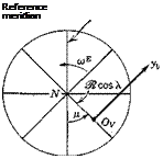
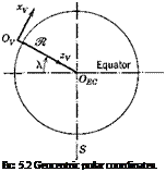
The motion of the Earth consists of a superposition of rotation on its axis, precession and nutation of its axis, rotation in its orbit around the sun, and additional motions of the solar system and the galaxy. Although any of these may be significant for problems of space flight, only the first-mentioned is likely to be of any importance for atmospheric flight, and even that one is often negligible We shall assume therefore that the Earth’s axis is fixed in inertial space, and that its motion is one of constant rotation at speed (oB on this axis. Its angular velocity vector is (see Figs. 4.2 and 5.2)
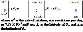
Подпись: ' 0 ' cos AE cos A 0 ; ЫЕЕ = 0 wE; b>Ev = 0 JcoE_ sin Ae_ sin where wE is the rate of rotation, one revolution per day, or 7.27 X Ю-5 rad/ sec, 1E is the latitude of 0E, and A is the latitude of 0V. (5.2,1)

ANGULAR VELOCITY cor OF Fv

Let the origin of Fy be at (A, p) at time t, and let it, in time 8t, undergo infinitesimal displacement to (A + dA, p + dp). It can be carried from its initial to its final positions by the two rotations (i)—6A around an axis
through the Earth center parallel to 0ryr and (ii) 6/t around 0ECzEO. Hence the angular displacement relative to Earth is given approximately by the vector

<5n = —}v 6X + kEC d/i (5.2,2)

where jу and kEO are unit vectors on Ovyv and 0ECzEC, respectively. The angular velocity of Fv relative to FE is then exactly

wv _ мя = lim *5 = _.rx + kEO/i (5.2,3)

st-o 6t

On taking components of (5.2,3) in Fr, and using (5.2,1) we get

(coE + ft) cos X

Подпись: (5.2,4)

Подпись: Reference meridian
Подпись: FIG. 5.2 Geocentric polar coordinates.

v

tli у =

_—{mE + ft) sin A.

The components of (iiV in Fw or FB are, of course, obtained by premultiplying (5.2,4) by Lwv or LBr, respectively.

ANGULAR VELOCITIES taw, w OF Fw, FB

The orientation of the moving frames Fw and FB are given relative to Fr by the Euler angles ip, в, ф (Sec. 4.3). Subscript W denotes Fw and no sub­script denotes FB. The result is derived below for FB, that for Fw being similar.

With reference to Fig. 4.9, let i, j, к be unit vectors of FB, the subscripts

Подпись: where
Подпись: R

Adding the subscript W in (5.2,8) and (5.2,9) to [P, Q, R], ф, 0, y>] gives the corresponding wind-axes equations. Note that these are transcendental differential equations for the Euler angles, and as such have exact analytical solutions only in special simple cases. Note also that the transformation matrix R, unlike L, is not orthogonal.

Equations (5.2,9) can be used to calculate the Euler angle rates from the relative angular velocities (P, Q, R). The latter can in turn be found from the “absolute” rates (p, q, r) by the first equality of (5.2,7), and (5.2,4), i. e.

with a similar equation for wind axes obtained by adding the subscript W and substituting hwv for Ъвг.

VELOCITY AND ACCELERATION IN AN ARBITRARILY MOVING FRAME

Подпись: Fid. 6.1 Moving coordinate system.

All of the reference frames with which we are concerned, except Fz of course, are in motion relative to inertial space. Fw and FB in particular have quite arbitrary motion, including acceleration of the origin, and rotation. Since in many applications, we want to express the position, inertial velocity,

and inertial acceleration of a particle in components parallel to the axes of these moving frames, we need general theorems that allow for arbitrary motion of the origin, and arbitrary angular velocity of the frame. These theorems are presented below.

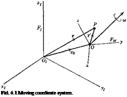
Let FM(Oxyz) be any moving frame with origin at 0 and with angular velocity ы relative to Fj. Let r = r0 + r’ be the position vector of a point P of FM (see Fig. 5.1). Then the velocity and acceleration of P relative to Fz are

Подпись: azVELOCITY AND ACCELERATION IN AN ARBITRARILY MOVING FRAME(6.1Д)

We want expressions for the velocity and acceleration of P in terms of the components of r’ in FM. Expanding the first of (5.1,1)

Подпись: (6.1,2)vi = Kj + r’l, •/

— V Г 7

Of 1 *

where v0 = r 0 is the velocity of 0 relative to Fr The velocity components in

F M are given by

yM — ^МІУІ — ^mAXoi + rI> ~ VoM + ^М1*І

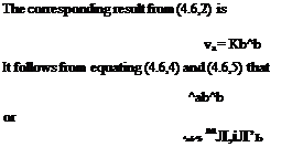
From the rule for transforming derivatives (4.6,10)

Подпись: (5.1,3)

whence

vm = vom + *м + &мг’м (5.1,4)

The first term of (5.1,4) is the velocity of 0 relative to Fz, the second is the velocity of P relative to FM, and the last is the “transport velocity,”

i. e. the velocity relative to FT of the point of FM that is momentarily coincident with P. The total velocity of P relative to FT is the sum of these three components. Following traditional practice in flight dynamics, we denote

(When necessary, subscripts are added to the components to identify particular moving frames.)

The scalar expansion of (5.1,4) is then

Vx = v0x + X+ qz — ry

%, = vov + y + rx— Pz (5.1,6)

vz — voz + г + py — qx

These expressions then give the components, parallel to the moving coordinate axes, of the velocity of P relative to the inertial frame.

On differentiating v7 and using (5.1,4) we find the components of inertial acceleration parallel to the FM axes to be

&m = ^міуі = Vm + &мум

= V0M + v’m + + <ол/гм + й>муом ь*мг’м + &м&мгм

= aojf + rM + &mt’m + %G>m*m + &>м&мг’м (5.1,7)

where a„M — v0ji + й>муом — ^міуо, is the acceleration of 0 relative to Fr.

The total inertial acceleration of P is seen to be composed of the following parts:

a0: the acceleration of the origin of the moving frame r’: the acceleration of P relative to the moving frame tor’: the “tangential” acceleration owing to rotational acceleration of the frame FM

2tor’: the Coriolis acceleration to cor’: the centripetal acceleration

Three of the five terms vanish when the frame F M has no rotation, and only r’ remains if it is inertial. Note that the Coriolis acceleration is perpendicular to to and r’, and the centripetal acceleration is directed along the perpen­dicular from P to to. The scalar expansion of (5.1,7) gives the required inertial acceleration components of P as

ax = aox + * + 2 qz — 2 ry — x{q* + r2) + y(pq — r) + z(pr + q)

ау = аоу + У + 2rx — 2P* + X(P4 + *) — УІР2 + ri) + г(ЯГ — P) (5-1,8)

az = aoz + » + 2py — 2 qx + x(pr — q) + y(qr + P) — z(P2 + ?2)

General equations of unsteady motion

The basis for analysis, computation; or simulation of the unsteady motions of flight vehicles is the mathematical model of the vehicle and of its sub­sidiary systems, i. e. their general equations of motion. Although a useful first step is to treat the vehicle as a single rigid body, and many important results can be derived from this model, we cannot in general avoid facing up to the reality of the situation, which is that vehicles are deformable and contain articulated or rotating subsystems such as control surfaces and engines. Furthermore the external forces and couples that act on aircraft and spacecraft are in general complicated functions of shape and of motion. This is especially true of the aerodynamic forces in atmospheric flight which are known only approximately. The attention that must be devoted to their representation dominates the formulation of the mathematical model. The forces and couples provided by the space environment (gravitational, magnetic, radiation pressure) are generally not so uncertain, and the problem of deriving an adequate mathematical model is consequently less difficult for spacecraft during extra-atmospheric operation.

In the following sections, we first treat the general motion of a particle over the rotating Earth, then derive the dynamical and kinematical equations for an arbitrary deformable vehicle in flight. Finally the equations for small disturbance from steady flight are presented in both dimensional and nondimensional form.

TRANSFORMATION OF THE DERIVATIVE OF A VECTOR

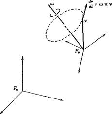
Consider a vector v that is being observed simultaneously from two frames Fa and Fb that have relative rotation—say Fb rotates with angular velocity a) relative to Fa, which we may regard as fixed. The rotation does not invalidate the argument of Sec. 4.4, so that

Уь = LbaVa (4‘4>3)

The derivatives of va and vb are of course

"V

‘V

Va =

к

and v6 =

%

-V

A.

where vx = (djdt)(vx ), etc. It is important to note that va and vb are not simply two sets of components of the same vector, but are actually two different vectors.

Now because Fb rotates relative to Fa, the direction cosines lti are changing with time, and the derivative of (4.4,3) is

Уь = ЬьЛ + (4-6’2)

or alternatively

У а ^аьУъ -6аїТ&

the second terms representing the effect of the rotation.

Since L must be independent of v, the matrix Lai) can readily be identified by considering the case when v6 is constant, see Fig. 4.12. For then, from the fundamental definitions of derivative and cross product, the derivative of v as seen from Fa is readily shown to be

dv

— = w x v

dt

(4.6,3)

The matrix equivalent of (4.6,3) is

У a = «Л

(4.6,4)

where

0 — <oz ft),

TRANSFORMATION OF THE DERIVATIVE OF A VECTOR

Fig. 4.12 Rotating vector of constant magnitude.


TRANSFORMATION OF THE DERIVATIVE OF A VECTOR

(4.6,5)


(4.6,6)


for all vh. Whence


and


^a ^ab^ba


Finally if the above argument be repeated with Fb considered fixed, and Fa having angular velocity —to, we clearly arrive at the reciprocal result

Lba = -«A. (4.6,7)

From (4.6,6) and (4.6,7), recalling that to is skew-symmetric so that toT = —to, the reader can readily derive the result


From (4.6,2), (4.6,6), and (4.6,7) we have the alternative relations

Подпись:^baFa ‘

(4.6,9)

Подпись: ^ba^a Подпись: П + &bVb Подпись: (4.6,10)

with two additional permutations made possible by (4.6,8). A particular form we shall finally want for application is that which uses the components of va transformed into Fb, viz.

4,7 TRANSFORMATION OF A MATRIX

Equation (4.6,8) is an example of the transformation of a matrix the elements of which are dependent on the frame of reference. Generally the matrix of interest A occurs in an equation of the form

Подпись: v = Au(4.7,1)

where the elements of the (physical) vectors u and v and of the matrix A are all dependent on the reference frame. We write (4.7,1) for each of the two frames Fa and Fb, i. e.

Подпись: va = АЛ V6 = Abu„(a)

(a) (4.7,2)

TRANSFORMATION OF THE DERIVATIVE OF A VECTOR Подпись: (4.7,3)

and transform the second to

By comparison with (4.7,2a) we get the general result

THE L MATRIX IN TERMS OF ROTATION ANGLES

THE L MATRIX IN TERMS OF ROTATION ANGLES THE L MATRIX IN TERMS OF ROTATION ANGLES

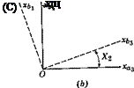
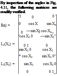
The transformations associated with single rotations about the three coordinate axes are now given. In each case Fa represents the initial frame, Fb the frame after rotation, and the notation for L identifies the axis and

Fie. 4.11 The three basic rotations, (a) About xai. (b) About хаґ (c) About xas.

the angle of the rotation (see Fig. 4.11). Thus in each case

Подпись: (4.5,1)vb = Ьг(ХХ

Подпись:(4.5,2)

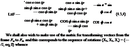
The transformation matrix for any sequence of rotations can be constructed readily from the above basic formulas. For the case of Euler angles, which rotate frame Fv into FB as defined in Sec. 4.3, the matrix corresponds to the sequence (X3, X2, Xj) = (ip, в, ф), giving

LBV = (ф) • Ь2(0) • L3(tp) (4.5,3)

[The sequence of angles in (4.5,3) is opposite to that of the rotations, since each transformation matrix premultiplies the vector arrived at in the previous step.] The result of multiplying the three matrices is

THE L MATRIX IN TERMS OF ROTATION ANGLES
Подпись: UBW

cos oq, cos /3 —cos oq. sin fi —sin oq sin /3 cos $ 0

sin oq. cos /? —sin oq sin /3 cos oq

PROPERTIES OF THE L MATRIX

Since va and vb are physically the same vector v, the magnitude of va must be the same as that of vb, i. e. v2 is an invariant of the transformation. From (4.4,3) this requires

= УьТУь = v/LbaTLbava = vjva (4.4,6)

It follows from the last equality of (4.4,6) that

Equation (4.4,6) is known as the orthogonality condition on L6a. From (4.4,6) it follows that,

lLJ2 = 1

and hence that |Lba| is never zero and the inverse of Lba always exists. In view of (4.4,6) we have, of course, that

haT = 4a-1 = 4b (4-4,7)

i. e. that the inverse and the transpose are the same. Equation (4.4,6) together with (4.4,36) yields a set of conditions on the direction cosines, i. e.

2 kks = Ь» (4-4,8)

k=1

It follows from (4.4,8) that the columns of Lbaare vectors that form an orthog­onal set (hence the name “orthogonal matrix”) and that they are of unit length.

Since (4.4,8) are a set of six relations among the nine lijy then only three of them are independent. These three are an alternative to the three inde­pendent Euler angles for specifying the orientation of one frame relative to another.

TRANSFORMATION OF A VECTOR

Let v be a vector with the components

TRANSFORMATION OF A VECTOR

The component of vai in the direction of xb. is vai cos (6a) where ()a denotes the angle between 0bxb, and 0axai (see Fig. 4.10). Thus by adding the three components of va. in the direction of xb. we get

з

% = I la% i = 1 • • • 3

3=1

(4.4,1)

where

l.. = cos (0„.)

(4.4,2)

are the nine

direction cosines. Equation (4.4,1) is

evidently the matrix

product

(«)

where

ha = Ы Ф)

(4.4,3)

Подпись: (4.4,4)
Подпись: where TRANSFORMATION OF A VECTOR

and constitutes the required transformation formula. Its inverse readily reverses the transformation to give

THE AERODYNAMIC ANGLES

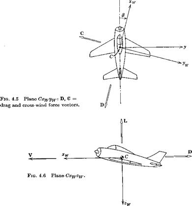
The linear motion V of the vehicle relative to the atmosphere can be given either by its three orthogonal components (и, v, w) in a body-axis system (see examples in Figs. 4.4 to 4.7), or alternatively by the magnitude V and two suitably defined angles. These angles, which are of fundamental importance in determining the aerodynamic forces that act on the vehicle, are defined thus:

Angle of attack (see Fig. 4.4):

otx = tan 1 – — я – < аж < 7Г (4.3,2)

и

Подпись: P- Подпись: ■ -і» sm — V Подпись: <P< Подпись: (4.3,3)

Sideslip angle (see Fig. 4.5):

Подпись:It is most important to note that oq. as here defined will be the same as that commonly used in aerodynamic theory and in wind-tunnel testing only if the body axis Gx is parallel to the basic aerodynamic reference direction, i. e. the mean aerodynamic chord or the zero-lift line. f Otherwise it differs by a constant. When the body axes used are stability axes Fs, the latter will normally be the case. It follows that the velocity components in the body axes are
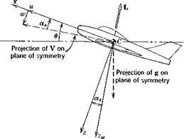
(4.3,4)

It will be observed that, in the sense of Euler angles, the aerodynamic angles relate the two frames Fw and FB by the rotation sequence (—/3, oq, 0) which carry the former into the latter.

DEFINITION OF THE ANGLES

THE VEHICLE EULER ANGLES

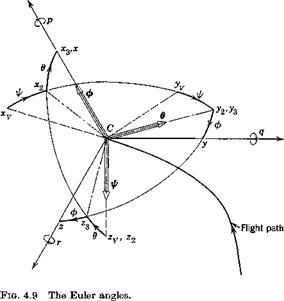
The orientation of any reference frame relative to another can be given by three angles, which are the consecutive rotations about the axes z, y, x in that order that carry one frame into coincidence with the other. This is a particular case of Euler angles. In flight dynamics, the Euler angles used are those which rotate the vehicle-carried vertical frame Fr into coincidence with the relevant axis system. Only two sets are commonly used, those for the body axes FB, and for the wind axes Fw. The angles are denoted (y>, в, ф) for body axes, including the special case Fs, and (ipw, 6W, фцг) for wind axes. Figure 4.9 shows the sequence of rotations.

(i) A rotation ф about OyZy, carrying the axes to Ovx^y2z2. гр is the azimuth angle

(ii) A rotation ® about Oyy2, carrying the axes to Ovx$3zs. в is the elevation angle

DEFINITION OF THE ANGLES

(iii) A rotation ф about 0vx3, carrying the axes to their final position Oyxyz. ф is the bank angle.

In order to avoid ambiguities which can otherwise result in the set of angles (y>, в, ф) the ranges are limited to

— 7Г < ip < TT or 0 < y> < 2tt

— – <:в <­2 2

— tr <, ф <. rr or 0 < ф < 2n

The Euler angles are then unique for most orientations of the vehicle, f although it should be noted that in a continuous steady rotation, such as rolling, the time variation of ф for example is a discontinuous sawtooth function.

As shown in Fig. 4.7, the angle 0lv is also commonly denoted by y, called the angle of climb for an obvious reason.

t There is an ambiguity for the angles defining a vertical dive, since (у, в, ф) = (a + b, —7t/2, —a) gives the same final orientation regardless of a. a = 0 would he the natural choice, and this special case does not seem to cause any difficulties.

STABILITY AXES Fs (Osxsyszs)

Stability axes are a special set of body axes used primarily in the study of small disturbances from a steady reference flight condition. If the reference flight condition is symmetric, i. e., if V lies in the plane of symmetry, then Fs coincides with the wind axes Fw in the reference condition, but departs from it, moving with the body, during the disturbance. If the reference flight condition is not symmetric, i. e. with sideslip, then 0sxs is chosen to lie on the projection of У in the plane of symmetry, with 0szs also in the plane of symmetry.

Trace of horizontal plane


Fig. 4.4 Plane of symmetry—Cxz; L = lift vector.


STABILITY AXES Fs (Osxsyszs)

Fie. 4.7 V, g plane.


Ill


STABILITY AXES Fs (Osxsyszs)STABILITY AXES Fs (Osxsyszs)

STABILITY AXES Fs (Osxsyszs)

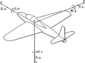
Fig. 4.8 Notation for body axes.

L = rolling moment p = rate of roll

M = pitching moment q — rate of pitch

N ~ yawing moment r — rate of yaw

[X, Y, Z] = components of resultant aerodynamic force

[u, v, w = components of velocity of G relative to atmosphere