Category Dynamics of. Atmospheric Flight

BODY-FIXED REFERENCE FRAME FB (BODY AXES, Oxyz)

Any set of axes fixed in a rigid body is a body-fixed reference frame. If the body is not rigid, i. e. if it has articulated parts such as control surfaces, or elastic motions, then the body axes are chosen to be those for which the resultant linear and angular momenta of the relative motions of articulation and elastic distortion vanish. This choice is always possible (see Sec. 5.1). The origin of the body axes is usually the mass center C. A particular set

of body axes with special properties are principal axes of inertia, denoted FP.

Flight vehicles almost invariably have a plane of symmetry (to a good approximation); this plane is chosen to be Cxz, with z directed “downward.”

Body axes play an especially important role in flight dynamics, and there is a tradition of notation associated with them. This is given in Fig. 4.8. Note that the subscript В is dropped when there is no possibility of con­fusion. The angular velocity of FB relative to Fx is to (p, q, r), and the components of VB are (и, v, w).

ATMOSPHERE-FIXED REFERENCE FRAME, FA (AXES 0AxAyAzA)

Since the relevant velocity for aerodynamic forces in atmospheric flight is that of the vehicle relative to the local atmosphere, it is essential to he concerned with the motion of the latter. When the atmosphere is, or is assumed to he, at rest relative to the Earth, then FA and *E are the same. If the atmosphere is in uniform motion relative to Fe, with velocity W, then Fa is convected relative to FE with that velocity.

If the motion of the atmosphere is nonuniform in time or space (as is in reality always the case) then FA is so chosen that the space and time averages of the motion of the atmosphere relative to FA taken over the space-time domain of concern in the problem, are zero. The motion of FA relative to Fe is in this case also a constant velocity W. (A treatment of flight in a turbulent atmosphere is given in Chapter 13.)

The velocity of the vehicle mass center relative to FA is denoted by V so that its velocity relative to Fb is

Vе = V + W (4.2,1)

4.2.4 AIR-TRAJECTORY REFERENCE FRAME Fw (WIND AXES, Owxwywzw)

This reference frame has origin fixed to the vehicle, usually at the mass center C, and the Owxw axis is directed along the velocity vector V of the vehicle relative to the atmosphere. The axis Owzw lies in the plane of symmetry of the vehicle if it has one, otherwise is arbitrary. If the atmosphere were at rest, then Ow would trace out the trajectory of the vehicle relative to the Earth, and Owxw would be always tangent to it. The frame Fw has angular velocity b>w relative to Fz. Although by doing so we depart from the general scheme, in the interest of simplicity we shall denote the components ofbiw in Fw by [pw, qw, rw].

VEHICLE-CARRIED VERTICAL FRAME, Fr (AXES OrYvzr)

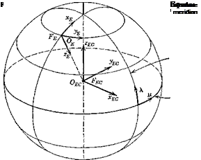
This is a reference frame in which the origin Or is attached to the vehicle, usually at the mass center <7, and in which Ovzr is directed vertically downward, i. e. along the local g vector. The directions of the remaining axes can be specified in any convenient way. We choose Ovxv to point to the north, and Oryv east. In many applications the origin of FE is near enough to the vehicle that Earth curvature is negligible, and then Fv has axes parallel to FE, as illustrated in Fig. 4.3.

VEHICLE-CARRIED VERTICAL FRAME, Fr (AXES OrYvzr)Fig. 4.3 The local (FE) and vehicle-carried (Fy) vertical reference frames.

Since Fe and Fy are both chosen so that their respective x axes point north, then Fe can be made parallel to Fr by the two consecutive rotations

(i) —ДА around 0EyE

(ii) Ay, around 0EOzEC

where ЛА = A — XE

Ay = у — yE

and (A, y) are latitude and longitude of Or

(XE, yE) are latitude and longitude of 0E.

The angular velocity of Fv relative to Fx is ыг.

EARTH-FIXED REFERENCE FRAME, FE (EARTH AXES

OexeIkze)

In many problems of airplane dynamics, the rotation of the Earth relative to Fj can be neglected, and any reference frame fixed to the Earth can be used as an inertial frame. In hypervelocity and space flight this is generally not the case, however, and the angular velocity of the Earth must usually be included in the analysis. Two Earth-fixed frames are of interest, as illustrated in Fig. 4.2. FEO is the “Earth-center” frame with origin at the center of the Earth and axis directions fixed by a reference point on the equator and the Earth’s axis. This frame is useful when the Earth’s rotation must be considered. FE is an Earth-surface frame, with origin near the vehicle if possible, and with 0EzE directed vertically down. 0ExEyE is the local horizontal plane, 0ExE points north, and 0EyE east.

,~N

EARTH-FIXED REFERENCE FRAME, FE (EARTH AXES

Q»s

DEFINITIONS OF REFERENCE FRAMES USED IN VEHICLE DYNAMICS

The principal reference frames used in vehicle dynamics are defined below, and illustrated in Figs. 4.2 to 4.7.

4.2.1 INERTIAL REFERENCE FRAME Fz (INERTIAL AXES, 07x7yzz7)

In every dynamics problem there must be an inertial reference frame, either explicitly defined, or lurking implicitly in the background. This frame is fixed, or in uniform rectilinear translation, relative to the distant stars; in it Newton’s second law is valid for the motion of a particle, in the sense that if f be the sum of all external forces acting on the particle, and a its acceleration relative to Fz, then f = та. If a is acceleration relative to a reference frame that has rotation, or acceleration of its origin, this equation does not hold, and additional terms that depend on the motion of the reference
frame must be added to the equation (see Sec. 5.1). The velocity of the vehicle mass center relative to FT is denoted Vz.

NOTATION

Let Fn and Fh be two right-handed reference frames, with coordinate axes denoted as in Fig. 4.1. Note that two alternative systems are used: (x, y, z) or (xv x2, ,r3), the choice at any time being governed by custom and

NOTATION

Fig. 4.1 Notations for coordinate axes.

convenience. In general the two frames have relative motion, both linear and angular.

Consider now the description of a typical vector which does not depend on the motion of the frame of reference. For example let Fa be the Earth, Fb a moving rigid vehicle, and the vector in question be the gravitational force exerted by the former on the latter, represented by g in Fig. 4.1. The vector g is the same for observers in both Fa and Fb in the sense that they would both find it to be of the same magnitude, and of the same orientation relative to any third frame. The components of g along the axes of Fa and Fb are of course in general dilferent, and we denote them by

(How to calculate one set of components from the other is treated in Sec. 4.4.)

A more complicated situation arises when we consider vectors that do depend on the motion of the reference frame, i. e. that are not the same for two observers, one in Fa and the other in Fb. For example, consider the veloc­ities of a point P relative to Fa and Fb. These are two different vectors, each of which may have its components given in the directions of either set of axes, leading to four sets of components.

The practice followed in this text is to use different symbols for physically different vectors, or appropriate subscripts or superscripts. Thus to usually represents the angular velocity of a reference frame relative to inertial space, and a superscript identifies the rotating frame. For example toB is the angular velocity of an Earth-fixed frame FE. Again, v0 and vc give the inertial veloci­ties of points 0 and G, the frame of reference for components being identified with a further subscript, so that v0 is the column matrix of the components of v0 along the axes of Fw (wind axes).

In the example of Fig. 4.1, we may let u® be the velocity of P relative to Fa and ub its velocity relative to Fb. The four sets of components are then

V, V and иЛ иь

each being a column matrix as in (4.1,1).

It should he emphasized that the transformation that transforms u® into ub is quite different from that which transforms ua® into ub®, and the two should not he confused (see Sec. 4.6).

Notwithstanding the above general rules, certain exceptions to this form of notation are made in the subsequent treatments. These are in conformity with a long tradition of usage in flight dynamics, and bring the main equations derived into harmony with most past and current North American literature on the subject.

Reference frames and transformations

When formulating and solving problems in flight dynamics, a number of frames of reference (coordinate axes) must be used for specifying relative positions and velocities, components of vectors (forces, velocities, acceler­ations etc.) and elements of matrices (aerodynamic derivatives, moments and products of inertia, etc.). The equations of motion may be written from the standpoint of an observer fixed in any of the reference frames, the choice being a matter of convenience and preference, and formulae must be available for transforming quantities of interest from one frame to another. For example, in an interplanetary space flight mission, one might need Earth – fixed axes, target-fixed axes, vehicle-fixed axes, and axes fixed to the distant stars. In atmospheric flight, we commonly use Earth-fixed axes, vehicle-fixed axes, trajectory-fixed axes, and atmosphere-fixed axes. The references frames needed for subsequent analytical developments are defined in the following, and a suitable system of notation is introduced.

LYAPUNOV STABILITY THEORY

The second general method for treating nonlinear systems is Lyapunov’s theory.

The stability of linear/invariant systems was shown in Sec. 3.3 to be com­pletely determined by the eigenvalues, and certain criteria were presented that could be applied to the characteristic equation to predict the stability properties of the roots. In that case we may say that we have investigated the stability by studying the properties of the solutions. This is possible of course only because we have an adequate theory for the solutions. For more general systems, this approach may not be possible since the solutions are not in general known. A method of treating the stability of equilibrium for any system, which does not require a knowledge of the solutions, has been given by Lyapunov (refs. 3.2, 3.8). We present below a brief outline of the main concepts but refer the reader to refs. 3.2 and 3.8 for a fuller treatment and for the methods of finding the appropriate Lyapunov functions.

We begin with a simple analogy by considering a ball at the bottom of a cup of arbitrary shape. The bottom is a position of stable equilibrium with respect to all disturbances small enough that the ball is not projected over the rim. This stable condition can be viewed from the standpoint of the
total energy E of the ball. If E is less than the potential energy ECIlt associ­ated with the height of the lowest point on the rim, then escape is impossible, and the system is stable. Note that the lowest point in the cup is a point of minimum potential energy, and that the minimum of E corresponds to equilibrium there. In any real case, there will be frictional dissipation, so that Ё is negative whenever there is motion, and if the ball is started any­where in the cup with E < ECIit, it will eventually come to rest at the bottom.

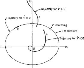
The Lyapunov theory is basically nothing more than a generalization of the above concept, and indeed for some physical systems, the energy itself is a suitable Lyapunov function. More generally, a Lyapunov function F(aq • • • xn) is any positive definite function of all the state variables x{ that is zero at the origin (an equilibrium state) and that increases monotonically within a region 3% of state space as one proceeds along the vector grad V = VV, i. e. it is a “cup-shaped” function with its “bottom” at the equilibrium point the stability of which is to be investigated. The critical question is whether V is positive, negative or zero in M. If positive, the state point “climbs up the V hill” proceeding ever farther from the origin, indicating instability. If negative, the state point descends continuously until it comes to rest at the origin, and the system is asymptotically stable. If V = 0, then the only motion possible is an orbital trajectory in which the state point remains on the surface V = const. These cases are illustrated in Fig. 3.25 for a two-dimensional state space. The essence of the problem is of course to find a suitable V function. Ideally one wants that function that gives the exact stability boundary in state space. This ideal is not usually achieved

LYAPUNOV STABILITY THEORY

Fig. 3.25 Trajectories in state space.

for other than linear/invariant systems, or simple mechanical ones such as the ball in the cup.

The great advantage of this approach is that V can be calculated directly from the differential equations, no solutions of them being needed. Let the equations be given

Since both V and/are known У can be calculated directly, and the stabihty properties inferred from how its sign varies with position in state space.

The main disadvantage of the Lyapunov approach is that the functions V are to a certain extent arbitrary, and hence can in most cases only provide a conservative estimate of stability. For example, if it is found that the limit of the monotonically increasing V for negative V is a certain surface 8 in state space, then it can be said that the system is stable for disturbances sufficiently small that the initial state point lies within S, but it is not known whether it may be stable beyond 8, since a different V function might have produced a larger domain of stability. It should be pointed out that for some problems in mechanics, as distinct from control systems (which have been the principal object of applications of Lyapunov theory) the Hamiltonian of the system can be a useful Lyapunov function (see Pringle, ref. 3.11).

The previous discussion has related to the stability of an equilibrium point (the origin in state space). However there are many important situations in the flight of aircraft and spacecraft when there is no steady state, as in the take-off and landing of aircraft, and the launch and reentry of spacecraft. If the state vector in such transient situations changes “slowly” with time (what constitutes “slowness” must be determined in each case), then a point-by-point stability analysis may be useful. In that case, each point on the trajectory is treated as a constant reference state (equilibrium) and the stabihty of disturbances from it is investigated in the manner discussed
above. When the transient is “rapid,” i. e. when the characteristic times (e. g. periods and damping times) of the disturbance motions are long enough that large changes can occur in the reference transient during these time intervals, then the “quasi-steady” analysis may be meaningless. In this case the stability analysis of the transient can be transformed into that of an equilibrium point as explained on p. 50, and the Lyapunov analysis for equilibrium again applied.

A general comment about the usefulness of stability analysis in aerospace systems is in order. It is a fact that stability is neither a necessary nor a sufficient condition for the successful performance of aerospace missions. A stable airplane may have unsatisfactory handling qualities, and vice versa; and an unstable flight path for a lifting entry vehicle may be perfectly acceptable within the tolerances on initial conditions that are practically available. Thus the determination of stability boundaries of nonlinear and time-varying systems does not appear to be an objective to which a great deal of effort should be applied. Of more direct import are appropriate performance criteria. These may take many forms depending on the vehicle and mission—for example, pilot rating in aircraft and terminal errors for reentry vehicles.

SINUSOIDAL DESCRIBING FUNCTION

When a stable linear system has a sinusoidal input x — A1eiat the steady – state output y(t) after the initial transients have decayed is a sinusoid of the same frequency, and the input/output relation is given by (3.4,20). A “well-behaved” nonlinear system with such an input will have a steady-state output that is also periodic, but not sinusoidal, other harmonics being present. Whereas the input spectrum is a “spike,” the output spectrum is a “comb.” Other behavior is conceivable, but the above describes the usual situation; we assume it to be the case here. Since the mean product of sinusoids of different frequency is zero, the only Fourier component of the output that has a nonvanishing correlation Rxy with the input is the fundamental, i. e. the component that has the same frequency £1 as the input.

Since Фху is the Fourier integral of Rxy, it follows that only the funda­mental component yf of у contributes to Фга. From (2.6,22) we have

ФХУі = lim – LX*(im;T)Yf(im;T)

T-+ 00 4:1

Подпись: (3.5,8)

Фхх = lim — X*(ia>; Т)Х(ію; T) t-> oo 4T

The ratio (3.5,7) then leads simply to

Щісо) = (3.5,9)

Х(га>)

where Yf(ia>) and X(ia>) are the Fourier transforms of the sinusoids, given in Table 2.2. Now if these sinusoids are described by

x = АіЄг’ш; yf = A2elQt

where Ax and A2 are the complex amplitudes of the input and output fundamental, respectively, we get, using item 3, Table 2.2,

Щісо) = ^ (3.5,10)

■d-i

which is identical with the frequency-response function given by (3.5,20) provided that we regard the fundamental as the total output.

Evidently the sinusoidal describing function leads to a remnant made up of all the lower and higher harmonics of the output.

TWO-INPUT DESCRIBING FUNCTIONS

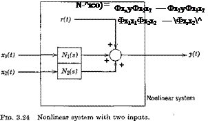
If two inputs to a nonlinear system contribute to the output y, as in Fig. 3.24 we may define two describing functions by the same principle as used

SINUSOIDAL DESCRIBING FUNCTION Подпись: (3.5,11)

above for one input. The method is basically the same, but the details are a little more involved. The result for Nj is

and that for N2(ico) is obtained by permuting the subscripts 1 and 2. Note that if aq and x2 are uncorrelated, so that the cross-spectral density ФХіХ2 = 0, then (3.5,11) reduces to (3.5,7), the formula for a single input.

STEADY-STATE DESCRIBING FUNCTION

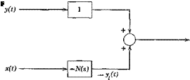
The relations implied by Fig. 3.22 can be reinterpreted as in Fig. 3.23. Now applying (3.4,50) we get the spectral density of r(t)

Фгг(ю) = Ф vv(a>) — Ж(іт)Фух(со) — 1У*(ісо)Фет(со) + N*(im)N(ia>№xx(co)

(3.5,2)

Since Фух = Ф*,, by (2.6,156), then

Ф„(со) = Ф„(а>) — [Фух{т)Щіт) + (Фда(со).Щі«))*] + N*{im)N(im) Фет(о)

(3.5,3)

We now wish to find the particular function N(im) that minimizes r2 — Фrr(co) dm. This can be done by the classical method of variational calculus, as follows.

Let us assume that N(im) is not exactly that which minimizes r2 but differs from it slightly, i. e.

N(im) = M(im) + ef(iw) (3.5,4)

where N(im) is the optimal function sought,/(ten) is an arbitrary continuous function, and e is a small parameter. Then N(im) is given by the solution of

– Рф„(со) dm =0 (3.5,5)

Эе J — GO €=0

When (3.5,4) is substituted into (3.5,3) and the l. h.s. of (3.5,5) is evaluated, the result is

f00 {-№,»/(»•<*>) + ф ;»/*(«>)]

J~ oo _ _

+ Ф«М[^*(мо)/(му) + f*(im)N(im)]}dm = 0 or

{І{іт)[Фхх(т)В*(іт) – Ф„»]

+ Г(іт)[Фхх(т)Щш) – Ф?»]} dm = 0 (3.5,6)

Since / (im) is an arbitrary function, the integral can only be zero if the two expressions in square brackets are both zero. Since one is simply the conjugate of the other they are simultaneously zero, and the required condition is

Подпись:

STEADY-STATE DESCRIBING FUNCTION

Щіт) = Щіт)