Category Dynamics of Flight

The Derivative ClfJ

The derivative C7 is of paramount importance. We have already noted its relation to roll stiffness and to the tendency of airplanes to fly with wings level. The primary contribution to Ct is from the wing—its dihedral angle, aspect ratio, and sweep all being important parameters.

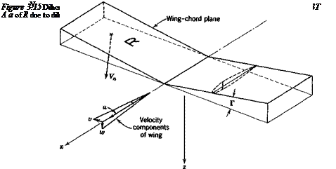
The effect of wing dihedral is illustrated in Fig. 3.15. With the coordinate system shown, the normal velocity component Vn on the right wing panel (R) is, for small di­hedral angle Г,

V„ = w cos Г + v sin Г == w + оГ

and that on the other panel is w – vT. The terms ±vT/V = ±/ЗГ represent opposite changes in the angle of attack of the two panels resulting from sideslip. The “up­wind” panel has its angle of attack and therefore its lift increased, and vice versa. The result is a rolling moment approximately linear in both /3 and Г, and hence a fixed

The Derivative ClfJ
value of for a given Г. This part of C/fl is essentially independent of wing angle of attack so long as the flow remains attached.

The Derivative ClfJ

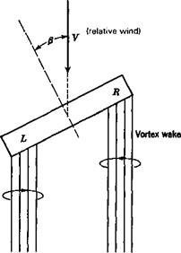
Even in the absence of dihedral, a flat lifting wing panel has a Cl/3 proportional to CL. Consider the case of Fig. 3.16. The vertical induced velocity (downwash) of the vortex wake is greater at L than at R simply by virtue of the geometry of the wake. Hence the local wing angle of attack and lift are less at L than at R, and a negative C, results. Since this effect depends, essentially linearly, on the strength of the vortex wake, which is itself proportional to the wing CL, then the result is ДClfj C, .

The Derivative ClfJ

The Derivative ClfJ

Roll Stiffness

Consider a vehicle constrained, as on bearings in a wind tunnel, to one degree of freedom-rolling about the x axis. The forces and moments resulting from a fixed dis­placement ф are fundamentally different in character from those associated with the rotations a and /3. In the first place if the x axis coincides with the velocity vector V, no aerodynamic change whatsoever follows from the fixed rotation ф (see Fig. 3.14). The aerodynamic field remains symmetrical with respect to the plane of symmetry, the resultant aerodynamic force remains in that plane, and no changes occur in any of the aerodynamic coefficients. Thus the roll stiffness ЭС/Эф = С, ф is zero in that case.

If the jc axis does not coincide with V, then a second-order roll stiffness results through the medium of the derivative ЭС/Э/3 = Clp. Let the angle of attack of the x axis be ax (see Fig. 1.7), then the velocity vector when ф — 0 is

Подпись: (3.11,1)Подпись: V,V cos ax 0

_ V sin ax _

After rolling through angle ф about Ox, the x component of the velocity vector re­mains unchanged, but the component V sin ax has projections on both of the new у

Roll Stiffness

Подпись: V2 = L,(</>)V, Подпись: V cos ax V sin ax sin ф _ V sin ax cos ф_ Подпись: (3.11,2)

and г axes. Thus there is now a sideslip, and hence, an angle /3 and a resulting rolling moment. Using the notation of Appendix A.4, we get for the velocity vector in the new reference frame after the rotation ф

Подпись: /3 = sin 1 — = sin Подпись: (sin ax sin ф) Подпись: (3.11,3)

Thus the sideslip component is v = V sin ax sin ф, and the sideslip angle is

As a result of this positive /3, and the usually negative Ct there is a restoring rolling moment that is,

ДCf = Ct sin-1 (sin ax sin ф) (a)

For small ax, we get the approximate result

ДС, = Clf} sin-1 (ax sin ф) = Clfptx sin ф (b) (3.11,4)

and if ф also is small,

Подпись: (c)Подпись: (a)ACt = С1рахФ

The stiffness derivative for rolling about Ox is then from (3.11,4a)

Подпись: ЭС; Э ф C‘P ( ЭС, Э ф Подпись:sin ax cos ф

1/2 or for ax < 1,

Подпись: (c)Подпись: or for cex, Ф <5 ]
Э c,

1ф * c"“-

Thus there is a roll stiffness that resists rolling if ax is >0, and would tend to keep the wings level. If rolling occurs about the wind vector, the stiffness is zero and the vehi­cle has no preferred roll angle. If ax < 0, then the stiffness is negative and the vehicle would roll to the position ф = 180°, at which point C, == 0 and С1ф < 0.

The above discussion applies to a vehicle constrained, as stated, to one degree of freedom. It does not, by any means, give the full answer for an unconstrained air­plane to the question: “What happens when the airplane rolls away from a wings – level attitude—does it tend to come back or not?” That answer can only be provided by a full dynamic analysis like the kind given in Chaps. 6 and 7. The roll stiffness ar­gument given above, however, does help in understanding the behavior of slender air­planes, ones with very low aspect ratio and hence small roll inertia. These tend, in re­sponse to aileron deflection when at angle of attack, to rotate about the x axis, not the velocity vector, and hence experience the roll stiffness effect at the beginning of the response.

Even though airplanes have no first-order aerodynamic roll stiffness, stable air­planes do have an inherent tendency to fly with wings level. They do so because of what is known as the dihedral effect. This is a complex pattern involving gravity and the derivative C, , which owes its existence largely to the wing dihedral (see Sec. 3.12). When rolled to an angle ф, there is a weight component mg sin ф in the у di­rection (Fig. 3.14). This induces a sideslip velocity to the right, with consequent (3 > 0, and a rolling moment C, /3 that tends to bring the wings level. The rolling and yawing motions that result from such an initial condition are, however, strongly cou­pled, so no significant conclusions can be drawn about the behavior except by a dy­namic analysis (see Chap. 6).

Yaw Control

In most flight conditions it is desired to maintain the sideslip angle at zero. If the air­plane has positive yaw stiffness, and is truly symmetrical, then it will tend to fly in this condition. However, yawing moments may act upon the airplane as a result of unsymmetrical thrust (e. g., one engine inoperative), slipstream rotation, or the un­symmetrical flow field associated with turning flight. Under these circumstances, /3 can be kept zero only by the application of a control moment. The control that pro­vides this is the rudder. Another condition requiring the use of the rudder is the steady sideslip, a maneuver sometimes used, particularly with light aircraft, to in­crease the drag and hence the glide path angle. A major point of difference between the rudder and the elevator is that for the former trimming the airplane is a secondary and not a primary function. Apart from this difference, the treatment of the two con­trols is similar. From (3.9,3) and (3.9,6), the rate of change of yawing moment with rudder deflection is given by

Yaw Control Yaw Control
Yaw Control

(3.10,1)


Yaw Control

This derivative is sometimes called the “rudder power.” It must be large enough to make it possible to maintain zero sideslip under the most extreme conditions of asymmetric thrust and turning flight.

A second useful index of the rudder control is the steady sideslip angle that can be maintained by a given rudder angle. The total yawing moment during steady sideslip may be written

Подпись: (3.10,2)Cn ~ Cnfi + Cns 8r

For steady motion, C„ = 0, and hence the desired ratio is

Yaw Control£

8r


The rudder hinge moment and control force are also treated in a manner similar to that employed for the elevator. Let the rudder hinge-moment coefficient be given

by

Chr = bxaF + b28r (3.10,4)

The rudder pedal force will then be given by

P = G^V2FS^cr{b, aF + b28r)

= g| V2FSrcr[bx{-(3 + a) + b28r] (3.10,5)

where G is the rudder system gearing.

The effect of a free rudder on the directional stability is found by setting Chr = 0 in (3.10,4). Then the rudder floating angle is

(3-10,6)

The vertical-tail lift coefficient with rudder free is found from (3.9,3) to be

b

C’lf = aFaF – a —aF

b2

t ar bt

= aFaF 1-— тЧ (3-10,7)

aF b2)

The free control factor for the rudder is thus seen to be of the same form as that for the elevator (see Sec. 2.6) and to have a similar effect.

THE VELOCITY RATIO VF/V

When the vertical tail is not in a propellor slipstream, VF/V is unity. When it is in a slipstream, the effective velocity increment may be dealt with as for a horizontal tail.

CONTRIBUTION OF PROPELLER NORMAL FORCE

The yawing moment produced by the normal force that acts on the yawed propeller is calculated in the same way as the pitching-moment increment dealt with in Sec. 3.4. The result is similar to (3.4,8):

Подпись: (3.9,8)= _ dCn„

Э/3 b S dap

This is known as the propeller fin effect and is negative (i. e., destabilizing) when the propeller is forward of the CG, but is usually positive for pusher propellers. There is a similar yawing moment effect for jet engines (see Exercise 3.7).

THE SIDEWASH FACTOR Эгг/Э/3

THE SIDEWASH FACTOR Эгг/Э/3

Generally speaking, the sidewash is difficult to estimate with engineering precision. Suitable wind-tunnel tests are required for this purpose. The contribution from the fuselage arises through its behavior as a lifting body when yawed. Associated with the side force that develops is a vortex wake which induces a lateral-flow field at the tail. The sidewash from the propeller is associated with the side force which acts upon it when yawed, and may be estimated by the method of (Ribner, 1944). The contribution from the wing is associated with the asymmetric structure of the flow which develops when the airplane is yawed. This phenomenon is especially pro­nounced with low-aspect-ratio swept wings. It is illustrated in Fig. 3.13.

Weathercock Stability (Yaw Stiffness)

Application of the static stability principle to rotation about the г axis suggests that a stable airplane should have “weathercock” stability. That is, when the airplane is at an angle of sideslip /3 relative to its flight path (see Fig. 3.11), the yawing moment produced should be such as to tend to restore it to symmetric flight. The yawing mo­ment N is positive as shown. Hence the requirement for yaw stiffness is that ЭМЭ/3 must be positive. The nondimensional coefficient of N is

^ N Cn hpV2Sb

Weathercock Stability (Yaw Stiffness) Подпись: (3.9,1)
Weathercock Stability (Yaw Stiffness)

and hence for positive yaw stiffness dCJd/3 must be positive. The usual notation for this derivative is

Weathercock Stability (Yaw Stiffness)

This quantity is analogous in some respects to the longitudinal stability parameter Cnia. It is estimated in a similar way by synthesis of the contributions of the various components of the airplane. The principal contributions are those of the body and the vertical-tail surface. By contrast with Cma, the wing has little influence in most cases, and the CG location is a weak parameter. Whether or not a positive value of Cnfj will produce lateral stability can only be determined by a full dynamic analysis such as is done in Chap. 6.

78 Chapter 3. Static Stability and Control—Part 2

Some data for estimating the contribution of the body to C„ is contained in Ap­pendix B. There are also given data suitable for estimation of the lift-curve slope of the vertical-tail surface. This may be used to calculate the tail contribution as shown below.

In Fig. 3.12 are shown the relevant geometry and the lift force LF acting on the vertical tail surface. If the surface were alone in an airstream, the velocity vector F would be that of the free stream, so that (cf. Fig. 3.11) aF would be equal to — /3. When installed on an airplane, however, changes in both magnitude and direction of the local flow at the tail take place. These changes may be caused by the propeller slipstream, and by the wing and fuselage when the airplane is yawed. The angular de­flection is allowed for by introducing the sidewash angle a, analogous to the down – wash angle e. cr is positive when it corresponds to a flow in the у direction; that is, when it tends to increase aF. Thus the angle of attack is

Подпись:Подпись: (3.9,3)aF = ~iв + a

and the lift coefficient of the vertical-tail surface is

CLf = aF(-p + cr) + arSr

The lift is then

Weathercock Stability (Yaw Stiffness)(3.9,4)

and the yawing moment is

X

CG

Weathercock Stability (Yaw Stiffness)

У

Weathercock Stability (Yaw Stiffness)

Weathercock Stability (Yaw Stiffness)

(3.9,6)


CnF=-VvCLF[ —


and the corresponding contribution to the weathercock stability is


dCnF

d/3


(т ЇЇ-ІІ


(3.9,7)


Weathercock Stability (Yaw Stiffness)

Lateral Aerodynamics

In the preceding sections of this and the previous chapter we discussed aerodynamic characteristics of symmetrical configurations flying with the velocity vector in the plane of symmetry. As a result the only nonzero motion variables were V, a, and q, and the only nonzero forces and moments were T, D, L, and M. We now turn to the cases in which the velocity vector is not in the plane of symmetry, and in which yaw­ing and rolling displacements (/3, ф) are present. The associated force and moment coefficients are Cv, C„ and C„.

One of the simplifying aspects of the longitudinal motion is that the rotation is about one axis only (the у axis), and hence the rotational stiffness about that axis is a very important criterion for the dynamic behavior. This simplicity is lost when we go to the lateral motions, for then the rotation takes place about two axes (x and z). The moments associated with these rotations are cross-coupled, that is, roll rotation p pro­duces a yawing moment Cn as well as rolling moment Ch and yaw displacement j8 and rate r both produce rolling and yawing moments. Furthermore, the roll and yaw controls are also often cross-coupled—deflection of the ailerons can produce signifi­cant yawing moments, and deflection of the rudder can produce significant rolling moments.

Another important difference between the two cases is that in “normal” flight— that is, steady rectilinear symmetric motion, all the lateral motion and force variables are zero. Hence there is no fundamental trimming problem—the ailerons and rudder would be nominally undeflected. In actuality of course, these controls do have a sec­ondary trimming function whenever the vehicle has either geometric or inertial asym­metries—for example, one engine off, or multiple propellers all rotating the same
way. Because the gravity vector in normal flight also lies in the plane of symmetry, the CG position is not a dominant parameter for the lateral characteristics as it is for the longitudinal. Thus the CG limits, (see Sec. 3.7) are governed by considerations deriving from the longitudinal characteristics.

THE AFT LIMIT

THE AFT LIMIT

The most rearward allowable location of the CG is determined by considerations of longitudinal stability and control sensitivity. The behavior of the five principal con­trol gradients are summarized in Fig. 3.10 for the case when the aerodynamic coeffi­cients are independent of speed. From the handling qualities point of view, none of the gradients should be “reversed,” that is, they should have the signs associated with low values of h. When the controls are reversible, this requires that h < h’n. If the controls are irreversible, and if the artificial feel system is suitably designed, then the control force gradient dP/dV can be kept negative to values of h > h’n, and the rear limit can be somewhat farther back than with reversible controls. The magnitudes of the gradients are also important. If they are allowed to fall to very small values the vehicle will be too sensitive to the controls. When the coefficients do not depend on speed, as assumed for Fig. 3.10, the NP also gives the stability boundary (this is proved in Chap. 6), the vehicle becoming unstable for h > h’n with free controls or h> h„ with fixed controls. If the coefficients dependent on speed, for example, Cm = Cm(M), then the CG boundary for stability will be different and may be forward of the NP.

As noted in Chap. 1, it is possible to increase the inherent stability of a flight ve­hicle. Stability augmentation systems (SAS) are in widespread use on a variety of air­planes and rotorcraft. If such a system is added to the longitudinal controls of an air­plane, it permits the use of more rearward CG positions than otherwise, but the risk of failure must be reckoned with, for then the airplane is reduced to its “inherent” sta­bility, and would still need to be manageable by a human pilot.

THE FORWARD LIMIT

As the CG moves forward, the stability of the airplane increases, and larger control movements and forces are required to maneuver or change the trim. The forward CG limit is therefore based on control considerations and may be determined by any one of the following requirements:

1. The control force per g shall not exceed a specified value.

2. The control-force gradient at trim, ЭP/dV, shall not exceed a specified value.

3. The control force required to land, from trim at the approach speed, shall not exceed a specified value.

4. The elevator angle required to land shall not exceed maximum up elevator.

5. The elevator angle required to raise the nose-wheel off the ground at takeoff speed shall not exceed the maximum up elevator.

CG Limits

One of the dominant parameters of longitudinal stability and control has been shown in the foregoing sections to be the fore-and-aft location of the CG (see Figs. 2.14, 2.18, 2.19, 2.25, 2.27, 2.28, and 3.2). The question now arises as to what range of CG position is consistent with satisfactory handling qualities. This is a critical design problem, and one of the most important aims of stability and control analysis is to provide the answer to it. Since aircraft always carry some disposable load (e. g., fuel, armaments), and since they are not always loaded identically to begin with (varia­tions in passenger and cargo load), it is always necessary to cater for a variation in the CG position. The range to be provided for is kept to a minimum by proper loca­

tion of the items of variable load, but still it often becomes a difficult matter to keep the handling qualities acceptable over the whole CG range. Sometimes the problem is not solved, and the airplane must be subjected to restrictions on the fore-and-aft dis­tribution of its variable load when operating at part load.

Ground Effect

At landing and takeoff airplanes fly for very brief (but none the less extremely impor­tant) time intervals close to the ground. The presence of the ground modifies the flow past the airplane significantly, so that large changes can take place in the trim and sta­bility. For conventional airplanes, the takeoff and landing cases provide some of the governing design criteria.

The presence of the ground imposes a boundary condition that inhibits the down­ward flow of air normally associated with the lifting action of the wing and tail. The reduced downwash has three main effects, being in the usual order of importance:

1. A reduction in e, the downwash angle at the tail.

2. An increase in the wing-body lift slope awb.

3. An increase in the tail lift slope a,.

The problem of calculating the stability and control near the ground then resolves it­self into estimating these three effects. When appropriate values of дє/да, awb, and a, have been found, their use in the equations of the foregoing sections will readily yield the required information. The most important items to be determined are the el­evator angle and control force required to maintain in level flight close to the ground. It will usually be found that the ratio aja is decreased by the presence of the ground. (2.3,23) shows that this would tend to move the neutral point forward. How­ever, the reduction in дє/да is usually so great that the net effect is a large rearward shift of the neutral point. Since the value of Cmo is only slightly affected, it turns out that the elevator angle required to trim at Cimax is much larger than in flight remote from the ground. It commonly happens that this is the critical design condition on the elevator, and it will govern the ratio SJSt, or the forward CG limit (see Sec. 3.7).