Category Flight Vehicle Aerodynamics

High Reynolds number flows

Typical aerodynamic flows of interest have very large Reynolds numbers, or Reref ^ 1, when based on a typical body dimension and freestream velocity and viscosity. Because the viscous-stress and heat conduc­tion terms involving t and q in equations (1.46),(1.47) are scaled by 1/Reref, these terms must therefore be negligible over most of the flow-field. The exception occurs very close to a body surface where V ^ 0 because of the no-slip condition. Here, in the momentum equation (1.46) only Vp remains to balance the viscous term, so the latter must remain significant sufficiently close to a wall. The result is that the action of viscosity and heat conductivity is confined to boundary layers and wakes, collectively termed the “shear layers” or “viscous regions.”

High Reynolds number flows

The viscous regions will be examined in much more detail in Chapters 3 and 4. For now, it will suffice to say that at the high Reynolds numbers of typical aerodynamic flows, the viscous regions, distinguished by significant t and q, are very thin compared with the body size, as sketched in Figure 1.9. This allows the assumption that the outer flow is inviscid, which is the basis of most aerodynamic models.

1.5.2 Standard coefficients

For the description of aerodynamic flows, a convenient non-dimensional form of the pressure is the pressure coefficient Cp. This is equivalent to the dimensionless pressure variable p used in Section 1.5.2, except

that Cp is shifted by some reference pressure pref, and its normalizing dynamic pressure qref contains the traditional factor of 3.

Cp = ^ , 9ref = ^PrefK-ef (1-53)

qref

In external aerodynamics applications, the reference quantities are normally chosen to correspond to freestream

flow, pref — Рж, VTef — , pref — Рж,

p рж 1 2

Cp = ——————— , <?oo = ^ржУж (1.54)

Яж

so that in the freestream we have Cp — 0. Since Cp measures the deviation of the pressure from pref, it is unaffected by any constant offset in all the pressures.

The skin friction coefficient, which is a non-dimensional wall shear stress, is normalized the same way.

Cf = — (1.55)

f Яж

An alternative normalization which uses the local dynamic pressure at a specific surface location gives the local skin friction coefficient Cf, which is more natural in boundary layer theory and will be treated in Chapter 4.

Dimensionless coefficients which quantify aerodynamic forces and moments are also extensively used in aerodynamics. These will be introduced in Chapter 5.

Unsteady-flow parameters

Nonuniform body motion, which will in general result in an unsteady flow, will have some time scale or frequency associated with the motion. The unsteadiness is typically imposed on the flow via the boundary
conditions, in particular the viscous no-slip condition (1.39) which takes on the following more general form for a body which is moving with local velocity Ubody in some time-varying manner.

V = Ubody(t) (on solid moving surface) (1.49)

Consider for example a sinusoidal body motion

Ubody(t) = Ui sin(wt) (1.50)

where ш is the motion frequency and U1 is some constant. The dimensionless form of (1.49) is

Подпись: (1.51) (1.52) V = U1 sin (Stref t)

where Stref is the Strouhal Number, also called the reduced frequency. This is an additional non-dimensional parameter which would need to be added to Table 1.2 for this unsteady flow case. Unsteady flows will be covered partly in Chapter 6, and in more detail in Chapter 7. The other chapters will focus on steady flows where Ubody = 0.

Non-dimensionalization

Non-dimensionalization can be viewed as the process of converting from standard to natural units. We can define all coordinates and field variables in terms of dimensionless variables () and the various natural units or scales listed in Table 1.1.

t

— t ^ref /Vref

p

— p pref

r

= r ^ref

p

= p prefVr2f

V

= V Vref

P

= P Pref

h0

= h0 ar2ef

k

= k kref

Подпись: dp dl + V- = 0 dV 1 - - рж + pV •VV = = -Vp + — V-r Яє ref _dho рж + pV ■ Vho = = М*Д ref ot M2f - + V • (f • v РЄ- ref p = 7-1 _ ( = p Y V ho 1 |y|2 Ml, 2 J Non-dimensionalization Подпись: (1.45) (1.46) (1.47) (1.48)

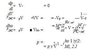
Substituting these into the compressible mass, momentum, total enthalpy, and ideal-gas state equations (1.33), (1.36), (1.38), (1.13), gives the corresponding dimensionless equations. The body force f and volume heating qV are omitted here, since they are not relevant in typical aerodynamic flows.

Here V() = 4efV() is the gradient in terms of r derivatives, and r, q arc the non-dimensional viscous stress tensor and heat flux vector, defined using Д, It, VV, Vh0.

Equations (1.45)-(1.48) have the same form as their dimensional counterparts, except for the appearance of four non-dimensional parameters formed with the reference scales, as summarized in Table 1.2. For incompressible flows, discussed in more detail in Section 1.8, the enthalpy and state equations (1.47),(1.48) are replaced by the simple relation p = constant. In this case, only (1.45),(1.46) are needed to fully determine the V, p fields and the resulting aerodynamic forces. Hence the Reynolds number is the only relevant aerodynamic parameter for steady incompressible flows.

Table 1.2: Non-dimensional parameters of a viscous flow. Parameters in bottom block are relevant only for compressible flows.

Parameter

Common name

Iferef = Preflref-^ref/Pref

Reynolds number

Ml’ei = W O’ref YY’ref = Cp Ah-ef / Pref

Y

Mach number Prandtl number ratio of specific heats

Units and Parameters

1.5.1 Unit systems

The quantitative description of any physical system, such as a fluid flow, requires using some set of units.

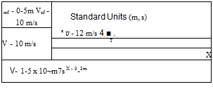
Two alternative sets of units, compared in Figure 1.8, can be used to describe any one given situation.

• Standard Units. Examples are m, s, kg (SI), or ft, s, slug (English). These are universally known, and hence are most convenient for describing a specific physical object, and also for recording raw experimental data.

Подпись: ref - 0-5m Vef - 10 m/s Standard Units (m, s) z U - 12 m/s 4 ■ . V - 10 m/s T X V- 1-5 x 10~m7s X - 0-2m Подпись: V7 - 1-0 Vref Natural Units (Vf,Vef) z u - 1-2 Vef T і .X V- 3-0 X loVfref X - 0-4 ^ V,- 1-0 Nondimensional Variables - U- 1-2 T ! ^X V- 3-0 X 106 X- 0-4

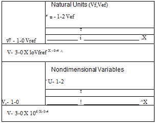
Natural Units (or Scales). Generic names are lref, Vref, pref, etc. Specific examples are c (chord), VL (freestream speed), pL (freestream density). These are most convenient for theoretical work, and for presenting reduced experimental data. Table 1.1 lists the scales which appear in aerodynamic flows.

Figure 1.8: Aerodynamic flow-field described in standard units, and alternatively in natural units. The natural units for this case are chosen to be the chord lref = c = 0.5m, and the freestream velocity Vref = VL = 10m/s. Using non-dimensional variables is equivalent to using natural units.

Table 1.1: Physical parameters, or scales, of aerodynamic flows. Scales in bottom block are relevant only for compressible flows. Units are: length l, time t, mass m, temperature 0.

Scale

Units

Typical specific choice

•^ref

length

l

c

airfoil chord

fret

velocity

l/t

kL

freestream speed

Pref

density

m/l3

P<L

freestream density

Pref

viscosity

m/It

(~h CO

freestream viscosity

O’ref

speed of sound

l/t

(loo

freestream speed of sound

^ref

heat conductivity

ml/t36

kcj

freestream value

Єр

heat capacity

l2/t2e

Єр

freestream value (~ constant)

7

ratio of specific heats

7

freestream value (~ constant)

The absolute reference pressure and temperature pref, Tref have been omitted from Table 1.1 because for ideal gases these are effectively redundant. Specifically, they can be defined from the other scales via the ideal-gas, speed of sound, and caloric relations.

pref — pref aref (1.43)

Tref — aref /cp (1.44)

Such derived-scale definitions only need to have the same dimensions. They do not need to be equalities, as in p = pa2/у and T = a2/(7—1 )cp. This allows the apparently missing 7 and 7—1 factors to be omitted from the pref and Tref definitions above.

Differential Conservation Equations

1.4.1 Divergence forms

Using Gauss’s Theorem for a general vector field quantity v(r),

© v ■ П dS = V ■ v dV (1.31)

Подпись: and setting vpV, the integral mass equation (1.27) can be restated in terms of only a volume integral.

dp

^ + V-(pV) dV = 0 (1.32)

Подпись: ^ + V ■ (pV) = 0 Подпись: (1.33)

Since this must hold for any control volume, the integrand must necessarily be zero for every point in the flow. The result is the divergence form of the differential mass equation.

The same process applied to the integral momentum and vergence differential forms.

Подпись:– Pt-

+ V ■ (pV = 4,. +

1.4.2 Convective forms

Подпись: where Подпись: DO D t Подпись: Ю dt Differential Conservation Equations Подпись: p— = P-^- + pV-VV = pf - Vp + V-T

Combining {momentum equation (1.34)} — V{mass equation (1.33)} and simplifying produces the con­vective form of the momentum equation,

Подпись: Figure 1.7: The substantial derivative Df/Dt gives rate of change of field quantity f (r,t) as felt by material element moving at V. The local derivative df/dt is rate of change at a fixed point r.

is the substantial derivative, which is the rate of change of any field quantity () as observed by a fluid element moving with velocity V, as shown in Figure 1.7.

Подпись: Dho P Dt Подпись: dh0 P трг + pV • Vho dt Подпись: dp dt Подпись: + qv + p f ■ V + V- (f ■ V) Подпись: V-q Подпись: (1.38)

Combining {enthalpy equation (1.35)} — ho{mass equation (1.33)} and simplifying produces the convective form of the enthalpy equation.

The mass, momentum, and enthalpy equations above, either in the divergence or convective forms, are collectively called the Navier-Stokes equations, although historically this term was originally first given to only the momentum equation (1.36) in its incompressible form, which will be considered in Section 1.8.

1.4.3 Surface boundary conditions

The appropriate boundary conditions for a viscous flow at a solid surface are the no-slip condition on V, and either a temperature condition or a heat-flux condition on h.

V = 0 (on solid fixed surface) (1.39)

either h = Cp Tbody (on surface with known temperature) (1.40)

or q ■ n = 0 (on surface at thermal equilibrium with fluid) (1.41)

Подпись: V ■ П = 0 Подпись: (on solid fixed surface) Подпись: (1.42)

For the idealization of an inviscid flow, the appropriate solid surface boundary condition is the following flow-tangency condition on V. No solid-surface boundary condition required for the temperature.

Integral conservation laws

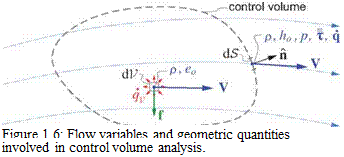
Подпись: Figure 1.6: Flow variables and geometric quantities involved in control volume analysis.

A general control volume placed in a flow-field is shown in Figure 1.6, with dV being an interior volume element, and dS being a boundary surface area element with outward unit normal n.

Integral mass equation

Integral conservation laws

The law of conservation of mass asserts that the time rate of change of the total mass in the volume, plus the net mass outflow rate through the surface of the volume, must sum to zero.

The second mass outflow term is seen to be the integral of the mass flux over the volume’s surface area.

Integral momentum equation

Подпись: jjj^f dV +|p(V.n)VdS Подпись: p f dV + Подпись: pn dS + Подпись: T • П d£ Подпись: (1.28)

Similarly, the law of conservation of momentum, or equivalently Newton’s Third Law, asserts that the time rate of change of the total momentum in the volume, plus the net momentum outflow rate through the surface of the volume, must sum to the total force acting on the interior and the surface of the volume.

Integral energy and enthalpy equations

The law of conservation of energy, or equivalently the First Law of Thermodynamics, asserts that the time rate of change of total energy, plus its net outflow rate, equals the sum of heat and work sources qV+wv in the interior, plus heat inflow and work — qS+wS at the boundary. The work terms are written out explicitly.

Integral conservation laws Подпись: p V ■ П ho dS Integral conservation laws Подпись: (1.30)

We then combine the lefthand energy-flux and righthand pressure-work terms together into an enthalpy flux term on the left, and replace peo with pho—p in the unsteady term, giving the alternative integral enthalpy equation.

Surface forces, work rate, heating

Surface forces, work rate, heating Подпись: Pressure Stress Viscous Stress Conductive Heat Flux -p n  T  qs ^i, wS wS q Pressure Work Viscous Work (shown per unit speed) (shown per unit speed)
Surface forces, work rate, heating

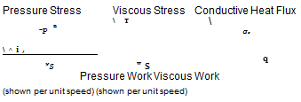
The fluid is subjected to stress, or force per unit area, acting on every area element of the surface of the control volume. This is broken down into the pressure stress —pn along and opposite to the surface-normal n, and the viscous stress vector т which can have any orientation, as shown in Figure 1.4.

Figure 1.4: Flow-field quantities p, p, VV together with a surface normal vector П define pressure and viscous stress forces acting on each surface point, with corresponding work contributions wS. Flow-Field quantities k, VT define the conductive heat flux vector q at each surface point, with corresponding normal flux component qS. These are all associated with molecular motion.

The pressure stress is isotropic (same magnitude for any П direction), and is the only stress which can be present in a fluid which either has a spatially-uniform velocity, or is in solid-body rotation, as shown in Figure 1.5. In contrast, the viscous stress is the result of the fluid’s deformation rate, or equivalently the strain rate, also shown in Figure 1.5. More precisely, the viscous stress vector т acting on a surface with unit normal П is given by

т = r ■ П (1.21)

where r is the viscous stress tensor, which is symmetric and therefore has six independent components.

Surface forces, work rate, heating Подпись: T = 0
Surface forces, work rate, heating Surface forces, work rate, heating

Uniform flow Solid-body rotation Simple shear flow

Figure 1.5: Viscous stresses occur in a fluid element which is subjected to a strain rate, as in the simple shear flow case.

Common gases and liquids like air and water are Newtonian fluids, for which the r components are pro­portional (via the viscosity factor) to the corresponding strain rate tensor components, which in turn are

Подпись: xx 1xy Txz Tyy Tyz • Tzz Surface forces, work rate, heating Surface forces, work rate, heating

constructed from the nine independent components of the velocity gradient matrix VV (see Batchelor [2]).

The contribution of the velocity divergence а (also called the dilatation rate) is subtracted to make the stress tensor have zero trace, Txx+Tyy+Tzz = 0. This zero-trace assumption is known as Stokes’s Hypothesis [3].

The pressure and viscous forces will also exert a work rate wS on the moving fluid

wS = (— pn + t • n) • V = – pV • n + V • r • n (1.24)

which has units of power per unit area. Unlike the power per unit volume rate wV given by (1.20), this wS is not an unambiguous field quantity since it is associated with some arbitrary surface whose orientation is specified by its normal vector n.

Surface forces, work rate, heating Подпись: k VT = k VT • n Surface forces, work rate, heating Подпись: (1.25) (1.26)

Fourier’s Law of heat conduction assumes that the conductive heat flux vector q is proportional to the heat conductivity k and the temperature gradient. This is analogous to the Newtonian viscous stress model, and is valid for most common solids and fluids, including air. For perfect gases the q vector can also be given via the static enthalpy gradient and viscosity via the Prandtl number. Its component qS along the normal of some arbitrary surface is the heat rate per unit area flowing through the surface.

Volume forces, work rate, heating

The fluid can be subjected to a force field f (r, t), the most common example being gravitational acceleration g. In a non-inertial frame this would also include d’Alembert, centrifugal, and Coriolis forces,

f (r, t) = g — U — О xr — О x (flxr) — 20xV (1.19)

where U(t) is the inertial velocity of the frame’s reference point, O(t) is the frame’s rotation, r is the position vector relative to the reference point, and V(r, t) is the velocity within the non-inertial frame. These quantities are diagrammed in Figure 7.1, in which V is denoted by Vrei. Flow-Field description in non-inertial frames will not be performed here, so that a constant f = g will be assumed in the most general case.

For application of f to the equations of fluid motion, the actual relevant quantity is p f, which has units of force per unit volume. When acting on fluid moving with local velocity V, this volume force will impart a work rate wv(r, t) equal to

Wv = p f ■ V (1.20)

which has units of power per unit volume. Possibly adding to this mechanical power is a thermal heating rate, quantified by some imposed body heating source density

qv = qv (r, f)

which also has units of power per unit volume. This might be from absorbed radiation or combustion. Outside a turbomachine combustor, and for the vast majority of external aerodynamic flows, qv is zero.

Mass, momentum, energy fluxes

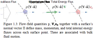
The mass flux is the local mass flow rate per unit area moving through the control volume’s surface, shown in Figure 1.3. It is equal to the density times the surface-normal component of the velocity.

(mass flux) = pV ■ n

Mass, momentum, energy fluxes

The mass flux also results in a momentum flux, defined as

momentum flux = (mass flux) x momentum/mass

= p(V ■ n) V

and which is a vector quantity. In an analogous manner, we can define the total internal energy flux,

total internal energy flux = (mass flux) x (total internal energy) /mass

= p(V ■ П) e0

where eo is the specific total energy, defined as the specific static energy plus the specific kinetic energy.

eo

= e + V2

(1.17)

V 2

= V ■V = u2 + v2 + w2

The specific total enthalpy ho and its flux are

defined the same way.

ho

= h + V2

(1.18)

total enthalpy flux

= p(V ■ n) ho

Conservation Laws

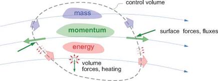
This section will apply the laws of conservation of mass, momentum, and energy to the fluid instantaneously inside any closed control volume which is fixed in space, shown in Figure 1.2.

Conservation Laws

Figure 1.2: Control volume in a flow-field. The time rates of the mass, momentum, and energy inside the control volume are related to the volume and surface forces and fluxes.


All flow-field quantities in general are functions of the spatial position vector r and of time t. Although the subsequent development uses general vector forms and operations, special cases will typically assume Cartesian axes, in which case the position and velocity vectors have the following Cartesian components.

r = x x + y y + z z (1.15)

= u x + v y + w z (1.16)