In Section 3.13, we superimposed a uniform flow and a doublet to synthesize the flow over a circular cylinder, as shown in Figure 3.26. In addition, we proved that both the lift and drag were zero for such a flow. However, the streamline pattern shown at the right of Figure 3.26 is not the only flow that is theoretically possible around a circular cylinder. It is the only flow that is consistent with zero lift. However, there are other possible flow patterns around a circular cylinder—different flow patterns
which result in a nonzero lift on the cylinder. Such lifting flows are discussed in this section.
Now you might be hesitant at this moment, perplexed by the question as to how a lift could possibly be exerted on a circular cylinder. Is not the body perfectly symmetric, and would not this geometry always result in a symmetric flow field with a consequent zero lift, as we have already discussed? You might be so perplexed that you run down to the laboratory, place a stationary cylinder in a low-speed tunnel, and measure the lift. To your satisfaction, you measure no lift, and you walk away muttering that the subject of this section is ridiculous—there is no lift on the cylinder. However, go back to the wind tunnel, and this time run a test with the cylinder spinning about its axis at relatively high revolutions per minute. This time you measure a finite lift. Also, by this time you might be thinking of other situations: spin on a baseball causes it to curve, and spin on a golfball causes it to hook or slice. Clearly, in real life there are nonsymmetric aerodynamic forces acting on these symmetric, spinning bodies. So, maybe the subject matter of this section is not so ridiculous after all. Indeed, as you will soon appreciate, the concept of lifting flow over a cylinder will start us on a journey which leads directly to the theory of the lift generated by airfoils, as discussed in Chapter 4.
Consider the flow synthesized by the addition of the nonlifting flow over a cylinder and a vortex of strength Г, as shown in Figure 3.32. The stream function for nonlifting flow over a circular cylinder of radius R is given by Equation (3.92):
 [3.92]
The stream function for a vortex of strength Г is given by Equation (3.114). Recall that the stream function is determined within an arbitrary constant; hence, Equation
(3.114) can be written as
![Lifting Flow Over a Cylinder Подпись: [3.115]](/img/3128/image581.gif) Г
Г
xj/2 = – In r + const
|
Nonlifting flow over a cylinder
|
|
|
Lifting flow over a cylinder
|
|
|
|
|
Figure 3.32 The synthesis of lifting flow over a circular cylinder.
|
|

Since the value of the constant is arbitrary, let
Г
Const =——– Inf? [3.116]
2л
Combining Equations (3.115) and (3.116), we obtain
іД2 = ^-1п^ [3.117]
І7Ї К
Equation (3.117) is the stream function for a vortex of strength Г and is just as valid as Equation (3.114) obtained earlier; the only difference between these two equations is a constant of the value given by Equation (3.116).
The resulting stream function for the flow shown at the right of Figure 3.32 is
jr = fx+f2
From Equation (3.118), if r = R, then jr = 0 for all values of в. Since i/f = constant is the equation of a streamline, r = R is therefore a streamline of the flow, but r = R is the equation of a circle of radius R. Hence, Equation (3.118) is a valid stream function for the inviscid, incompressible flow over a circular cylinder of radius R, as shown at the right of Figure 3.32. Indeed, our previous result given by Equation (3.92) is simply a special case of Equation (3.118) with Г = 0.
The resulting streamline pattern given by Equation (3.118) is sketched at the right of Figure 3.32. Note that the streamlines are no longer symmetrical about the horizontal axis through point O, and you might suspect (correctly) that the cylinder will experience a resulting finite normal force. However, the streamlines are symmetrical about the vertical axis through O, and as a result the drag will be zero, as we prove shortly. Note also that because a vortex of strength Г has been added to the flow, the circulation about the cylinder is now finite and equal to Г.
The velocity field can be obtained by differentiating Equation (3.118). An equally direct method of obtaining the velocities is to add the velocity field of a vortex to the velocity field of the nonlifting cylinder. (Recall that because of the linearity of the flow, the velocity components of the superimposed elementary flows add directly.) Hence, from Equations (3.93) and (3.94) for nonlifting flow over a cylinder of radius R, and Equations (3.111a and b) for vortex flow, we have, for the lifting flow over a cylinder of radius R,
To locate the stagnation points in the flow, set Vr = Vq = 0 in Equations (3.119) and (3.120) and solve for the resulting coordinates (г, в):


[3.121]
From Equation (3.121), r = R. Substituting this result into Equation (3.122) and solving for в, we obtain
Since Г is a positive number, from Equation (3.123) в must be in the third and fourth quadrants. That is, there can be two stagnation points on the bottom half of the circular cylinder, as shown by points 1 and 2 in Figure 3.33a. These points are located at (R, в), where в is given by Equation (3.123). However, this result is valid only when Г/4л V^R < 1. If Г/4л R > 1, then Equation (3.123) has no
meaning. If Г/4л V^R = 1, there is only one stagnation point on the surface of the cylinder, namely, point (R, —л/2) labeled as point 3 in Figure 3.33b. For the case of Г/4л V^R > 1, return to Equation (3.121). We saw earlier that it is satisfied by r = R; however, it is also satisfied by 9 = л/2 or —л/2. Substituting в = —л/2 into Equation (3.122), and solving for r, we have
 [3.124]
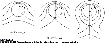
Hence, for Г|4лУ00R > 1, there are two stagnation points, one inside and the other outside the cylinder, and both on the vertical axis, as shown by points 4 and 5 in Figure 3.33c. [How does one stagnation point fall inside the cylinder? Recall that r = R, or t/r = 0, is just one of the allowed streamlines of the flow. There is a theoretical flow
inside the cylinder—flow that is issuing from the doublet at the origin superimposed with the vortex flow for r < R. The circular streamline r = R is the dividing streamline between this flow and the flow from the freestream. Therefore, as before, we can replace the dividing streamline by a solid body—our circular cylinder—and the external flow will not know the difference. Hence, although one stagnation point falls inside the body (point 5), we are not realistically concerned about it. Instead, from the point of view of flow over a solid cylinder of radius R, point 4 is the only meaningful stagnation point for the case Г/Ап V^R > 1.]
The results shown in Figure 3.33 can be visualized as follows. Consider the inviscid incompressible flow of given freestream velocity VTO over a cylinder of given radius R. If there is no circulation (i. e., if Г = 0), the flow is given by the sketch at the right of Figure 3.26, with horizontally opposed stagnation points A and B. Now assume that a circulation is imposed on the flow, such that Г < An V^R. The flow sketched in Figure 3.33a will result; the two stagnation points will move to the lower surface of the cylinder as shown by points 1 and 2. Assume that Г is further increased until Г = AnV^R. The flow sketched in Figure 3.33b will result, with only one stagnation point at the bottom of the cylinder, as shown by point 3. When Г is increased still further such that Г > AnV^R, the flow sketched in Figure 3.33c will result. The stagnation point will lift from the cylinder’s surface and will appear in the flow directly below the cylinder, as shown by point 4.
From the above discussion, Г is clearly a parameter that can be chosen freely. There is no single value of Г that “solves” the flow over a circular cylinder; rather, the circulation can be any value. Therefore, for the incompressible flow over a circular cylinder, there are an infinite number of possible potential flow solutions, corresponding to the infinite choices for values of Г. This statement is not limited to flow over circular cylinders, but rather, it is a general statement that holds for the incompressible potential flow over all smooth two-dimensional bodies. We return to these ideas in subsequent sections.
From the symmetry, or lack of it, in the flows sketched in Figures 3.32 and 3.33, we intuitively concluded earlier that a finite normal force (lift) must exist on the body but that the drag is zero; that is, d’Alembert’s paradox still prevails. Let us quantify these statements by calculating expressions for lift and drag, as follows.
The velocity on the surface of the cylinder is given by Equation (3.120) with r — R:
In turn, the pressure coefficient is obtained by substituting Equation (3.125) into Equation (3.38):
In Section 1.5, we discussed in detail how the aerodynamic force coefficients can be obtained by integrating the pressure coefficient and skin friction coefficient over the surface. For inviscid flow, Cf =0. Hence, the drag coefficient c, i is given by Equation (1.16) as
1 fTE
Cd — — — / {Cp, u Cp i) dy
c J LE
1 fTE 1 fTE
or cd = – CptUdy————– Cpjdy [3.127]
c J LE C J LE
Converting Equation (3.127) to polar coordinates, we note that
у = R sin 9 dy = R cos 9 d9 [3.128]
Substituting Equation (3.128) into (3.127), and noting that c = 2R, we have
1 1 Г2л
cd — — I Cp. u cos 9 d6 — – / Cpj cos Odd [3.129]
2 Jjz 2 Jji
The limits of integration in Equation (3.129) are explained as follows. In the first integral, we are integrating from the leading edge (the front point of the cylinder), moving over the top surface of the cylinder. Hence, в is equal to л at the leading edge and, moving over the top surface, decreases to 0 at the trailing edge. In the second integral, we are integrating from the leading edge to the trailing edge while moving over the bottom surface of the cylinder. Hence, в is equal to л at the leading edge and, moving over the bottom surface, increases to 2л at the trailing edge. In Equation (3.129), both Cp u and Cpd are given by the same analytic expression for Cp, namely, Equation (3.126). Hence,
we have
Equation (3.140) gives the lift per unit span for a circular cylinder with circulation Г. It is a remarkably simple result, and it states that the lift per unit span is directly proportional to circulation. Equation (3.140) is a powerful relation in theoretical
aerodynamics. It is called the Kutta-Joukowski theorem, named after the German mathematician M. Wilheim Kutta (1867-1944) and the Russian physicist Nikolai E. Joukowski (1847-1921), who independently obtained it during the first decade of this century. We will have more to say about the Kutta-Joukowski theorem in Section 3.16.
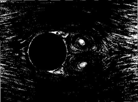
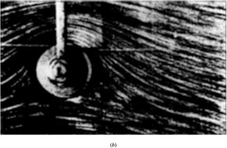
What are the connections between the above theoretical results and real life? As stated earlier, the prediction of zero drag is totally erroneous—viscous effects cause skin friction and flow separation which always produce a finite drag, as will be discussed in Chapters 15 to 20. The inviscid flow treated in this chapter simply does not model the proper physics for drag calculations. On the other hand, the prediction of lift via Equation (3.140) is quite realistic. Let us return to the wind-tunnel experiments mentioned at the beginning of this chapter. If a stationary, nonspinning cylinder is placed in a low-speed wind tunnel, the flow field will appear as shown in Figure 3.34a. The streamlines over the front of the cylinder are similar to theoretical predictions, as sketched at the right of Figure 3.26. However, because of viscous effects, the flow separates over the rear of the cylinder, creating a recirculating flow in the wake downstream of the body. This separated flow greatly contributes to the finite drag measured for the cylinder. On the other hand, Figure 3.34a shows a reasonably
|
(«)
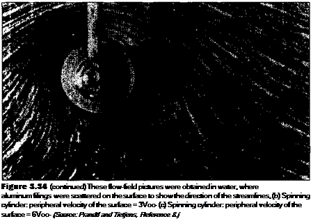
Figure 3.34 These flow-field pictures were obtained in water, where aluminum filings were scattered on the surface to show the direction of the streamlines.
(a) Shown above is the case for the nonspinning cylinder. (Source: Prandtl and Tietjens, Reference 8.)
|
(c)
symmetric flow about the horizontal axis, and the measurement of lift is essentially zero. Now let us spin the cylinder in a clockwise direction about its axis. The resulting flow fields are shown in Figure 3.34b and c. For a moderate amount of spin (Figure
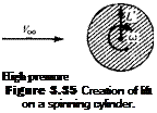
3.34b), the stagnation points move to the lower part of the cylinder, similar to the theoretical flow sketched in Figure 3.33a. If the spin is sufficiently increased (Figure 3.34c), the stagnation point lifts off the surface, similar to the theoretical flow sketched in Figure 3.33c. And what is most important, a finite lift is measured for the spinning cylinder in the wind tunnel. What is happening here? Why does spinning the cylinder produce lift? In actuality, the friction between the fluid and the surface of the cylinder tends to drag the fluid near the surface in the same direction as the rotational motion. Superimposed on top of the usual nonspinning flow, this “extra” velocity contribution creates a higher-than-usual velocity at the top of the cylinder and a lower-than-usual velocity at the bottom, as sketched in Figure 3.35. These velocities are assumed to be just outside the viscous boundary layer on the surface. Recall from Bernoulli’s equation that as the velocity increases, the pressure decreases. Hence, from Figure 3.35, the pressure on the top of the cylinder is lower than on the bottom. This pressure imbalance creates a net upward force, that is, a finite lift. Therefore, the theoretical prediction embodied in Equation (3.140) that the flow over a circular cylinder can produce a finite lift is verified by experimental observation.
The general ideas discussed above concerning the generation of lift on a spinning circular cylinder in a wind tunnel also apply to a spinning sphere. This explains why a baseball pitcher can throw a curve and how a golfer can hit a hook or slice—all of which are due to nonsymmetric flows about the spinning bodies, and hence the generation of an aerodynamic force perpendicular to the body’s angular velocity vector. This phenomenon is called the Magnus effect, named after the German engineer who first observed and explained it in Berlin in 1852.
It is interesting to note that a rapidly spinning cylinder can produce a much higher lift than an airplane wing of the same planform area; however, the drag on the cylinder is also much higher than a well-designed wing. As a result, the Magnus effect is not employed for powered flight. On the other hand, in the 1920s, the German engineer Anton Flettner replaced the sail on a boat with a rotating circular cylinder with its axis vertical to the deck. In combination with the wind, this spinning cylinder provided propulsion for the boat. Moreover, by the action of two cylinders in tandem and rotating in opposite directions, Flettner was able to turn the boat around. Flettner’s device was a technical success, but an economic failure because the maintenance on the machinery to spin the cylinders at the necessary high rotational speeds was too costly. Today, the Magnus effect has an important influence on the performance of spinning missiles; indeed, a certain amount of modem high-speed aerodynamic research has focused on the Magnus forces on spinning bodies for missile applications.
Low pressure
 V
V
V
|

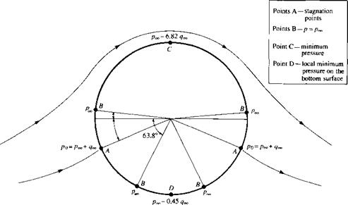
Figure 3.36 Values of pressure at various locations on the surface of a circular cylinder; lifting case with finite circulation. The values of pressure correspond to the case discussed in Example 3.10.
|
|
There are four points on the circular cylinder where p = Poo – These are sketched in Figure 3.36, along with the stagnation point locations. As shown in Example 3.10, the minimum pressure occurs at the top of the cylinder and is equal to рх — 6.82qx. A local minimum pressure occurs at the bottom of the cylinder, where в = Зл/2. This local minimum is given by
Hence, at the bottom of the cylinder, p = px — 0.45^.
![]()
 [2.15]





 Flow exerts p and r on the surface of the body, giving a resultant aerodynamic force R


![Lifting Flow Over a Cylinder Подпись: [3.119] [3.120]](/img/3128/image590.gif)


 V
V
