Category Fundamentals of Aerodynamics

Momentum Equation

Newton’s second law is frequently written as

F = та [2.55]

where F is the force exerted on a body of mass m and a is the acceleration. However, a more general form of Equation (2.55) is

F = — (mV) [2.56]

at

which reduces to Equation (2.55) for a body of constant mass. In Equation (2.56), mV is the momentum of a body of mass m. Equation (2.56) represents the second fundamental principle upon which theoretical fluid dynamics is based.

Physical principle Force = time rate of change of momentum

We will apply this principle [in the form of Equation (2.56)] to the model of a finite control volume fixed in space as sketched in Figure 2.17. Our objective is to obtain expressions for both the left and right sides of Equation (2.56) in terms of the familiar flow-field variables p, p, V, etc. First, let us concentrate on the left side of Equation

(2.56) , i. e., obtain an expression for F, which is the force exerted on the fluid as it flows through the control volume. This force comes from two sources:

1. Body forces: gravity, electromagnetic forces, or any other forces which “act at a distance” on the fluid inside V.

2. Surface forces: pressure and shear stress acting on the control surface S.

Let f represent the net body force per unit mass exerted on the fluid inside V. The body force on the elemental volume dV in Figure 2.17 is therefore

pi dV

Momentum Equation

and the total body force exerted on the fluid in the control volume is the summation of the above over the volume V:

where the negative sign indicates that the force is in the direction opposite of dS. That is, the control surface is experiencing a pressure force which is directed into the control volume and which is due to the pressure from the surroundings, and examination of Figure 2.17 shows that such an inward-directed force is in the direction opposite of
dS. The complete pressure force is the summation of the elemental forces over the entire control surface:

Подпись: Pressure force =image119[3.58]

In a viscous flow, the shear and normal viscous stresses also exert a surface force. A detailed evaluation of these viscous stresses is not warranted at this stage of our discussion. Let us simply recognize this effect by letting Fuscous denote the total viscous force exerted on the control surface. We are now ready to write an expression for the left-hand side of Equation (2.56). The total force experienced by the fluid as it is sweeping through the fixed control volume is given by the sum of Equations (2.57) and (2.58) and Fviscous:

F=j^pfdV-^pdS + Fviscous [3.59]

v s

Now consider the right side of Equation (2.56). The time rate of change of momentum of the fluid as it sweeps through the fixed control volume is the sum of two terms:

Подпись: [2.60a]Net flow of momentum out
of control volume across surface S

Momentum Equation Подпись: [2.60Ы

and

Consider the term denoted by G in Equation (2.60a). The flow has a certain momen­tum as it enters the control volume in Figure 2.17, and, in general, it has a different momentum as it leaves the control volume (due in part to the force F that is exerted on the fluid as it is sweeping through V). The net flow of momentum out of the control volume across the surface S is simply this outflow minus the inflow of momentum across the control surface. This change in momentum is denoted by G, as noted above. To obtain an expression for G, recall that the mass flow across the elemental area dS is (pV • dS); hence, the flow of momentum per second across dS is

(pV • dS)V

Momentum Equation Подпись: [2.61]

The net flow of momentum out of the control volume through S is the summation of the above elemental contributions, namely,

In Equation (2.61), recall that positive values of (pV • dS) represent mass flow out of the control volume, and negative values represent mass flow into the control volume. Hence, in Equation (2.61) the integral over the whole control surface is a combination of positive contributions (outflow of momentum) and negative contributions (inflow
of momentum), with the resulting value of the integral representing the net outflow of momentum. If G has a positive value, there is more momentum flowing out of the control volume per second than flowing in; conversely, if G has a negative value, there is more momentum flowing into the control volume per second than flowing out.

Now consider H from Equation (2.60b). The momentum of the fluid in the elemental volume dV shown in Figure 2.17 is

(,pdV)

The momentum contained at any instant inside the control volume is therefore

v

and its time rate of change due to unsteady flow fluctuations is

pVdV [2.62]

v

Combining Equations (2.61) and (2.62), we obtain an expression for the total time rate of change of momentum of the fluid as it sweeps through the fixed control volume, which in turn represents the right-hand side of Equation (2.56):

(mV) = G + H = <jlj> (pV • dS)V + Pv dV [2.63]

S V

Hence, from Equations (2.59) and (2.63), Newton’s second law,

d

— (mV) = F dt

applied to a fluid flow is

image120

[2.64]

Equation (2.64) is the momentum equation in integral form. Note that it is a vector equation. Just as in the case of the integral form of the continuity equation, Equation

(2.64) has the advantage of relating aerodynamic phenomena over a finite region of space without being concerned with the details of precisely what is happening at a given distinct point in the flow. This advantage is illustrated in Section 2.6.

From Equation (2.64), we now proceed to a partial differential equation which relates flow-field properties at a point in space. Such an equation is a counterpart to the differential form of the continuity equation given in Equation (2.52). Apply

Momentum Equation

where the subscripts у and z on / and T denote the у and z components of the body and viscous forces, respectively. Equations (2.70a to c) are the scalar x, y, and г components of the momentum equation, respectively; they are partial differential equations that relate flow-field properties at any point in the flow.

Подпись: and image124 Momentum Equation

Note that Equations (2.64) and (2.70a to c) apply to the unsteady, three-dimensional flow of any fluid, compressible or incompressible, viscous or inviscid. Specialized to a steady (d/dt = 0), inviscid (FviSCous = 0) flow with no body forces (f = 0), these equations become

Since most of the material in Chapters 3 through 14 assumes steady, inviscid flow with no body forces, we will have frequent occasion to use the momentum equation in the forms of Equations (2.71) and (2.72a to c).

The momentum equations for an inviscid flow [such as Equations (2.72a to c)] are called the Euler equations. The momentum equations for a viscous flow [such as Equations (2.70a to c) are called the Navier-Stokes equations. We will encounter this terminology in subsequent chapters.

Vortex Flow: Our Fourth Elementary Flow

Again, consulting our chapter road map in Figure 3.4, we have discussed three ele­mentary flows—uniform flow, source flow, and doublet flow—and have superimposed these elementary flows to obtain the nonlifting flow over several body shapes, such as ovals and circular cylinders. In this section, we introduce our fourth, and last, elementary flow; vortex flow. In turn, in Sections 3.15 and 3.16, we see how the superposition of flows involving such vortices leads to cases with finite lift.

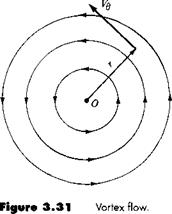
Consider a flow where all the streamlines are concentric circles about a given point, as sketched in Figure 3.31. Moreover, let the velocity along any given circular streamline be constant, but let it vary from one streamline to another inversely with distance from the common center. Such a flow is called a vortex flow. Examine Figure 3.31; the velocity components in the radial and tangential directions are Vr and Vg, respectively, where Vr = 0 and Vg = constant/r. It is easily shown (try it yourself) that (1) vortex flow is a physically possible incompressible flow, that is, V • V = 0 at every point, and (2) vortex flow is irrotational, that is, V x V = 0, at every point except the origin.

From the definition of vortex flow, we have

Vortex Flow: Our Fourth Elementary Flow

[3.104]


image256

Подпись: or Подпись: Г image257 Подпись: [3.105]

To evaluate the constant C, take the circulation around a given circular streamline of radius r

Comparing Equations (3.104) and (3.105), we see that

Г

C =———- [3.106]

2jr

Therefore, for vortex flow, Equation (3.106) demonstrates that the circulation taken about all streamlines is the same value, namely, Г = —2л C. By convention, Г is called the strength of the vortex flow, and Equation (3.105) gives the velocity field for a vortex flow of strength Г. Note from Equation (3.105) that Vg is negative when Г is positive; that is, a vortex of positive strength rotates in the clockwise direction. (This is a consequence of our sign convention on circulation defined in Section 2.13, namely, positive circulation is clockwise.)

We stated earlier that vortex flow is irrotational except at the origin. What happens at r = 0? What is the value of V x V at r = 0? To answer these questions, recall Equation (2.137) relating circulation to vorticity:

Г = ~jj(v x V)- dS [2.137]

Combining Equations (3.106) and (2.137), we obtain

Подпись:2л C = j j (V x V) • dS

Подпись: 2 лC Vortex Flow: Our Fourth Elementary Flow Подпись: [3.108]

Since we are dealing with two-dimensional flow, the flow sketched in Figure 3.31 takes place in the plane of the paper. Hence, in Equation (3.107), both V x V and dS are in the same direction, both perpendicular to the plane of the flow. Thus, Equation (3.107) can be written as

In Equation (3.108), the surface integral is taken over the circular area inside the streamline along which the circulation Г = —2ттС is evaluated. However, Г is the same for all the circulation streamlines. In particular, choose a circle as close to the origin as we wish (i. e., let r —»■ 0). The circulation will still remain Г = —2лС. However, the area inside this small circle around the origin will become infinitesimally small, and

JJV x\dS ^ V x\dS [3.109]

s

Combining Equations (3.108) and (3.109), in the limit as r —>■ 0, we have

2тсС = |V x V| dS

2 тсС r,

or |VxV| = ——- [3.110]

dS

However, as r —>■ 0, dS —»■ 0. Therefore, in the limit as r —»■ 0, from Equation (3.110), we have

Подпись: oo|V x V|

Conclusion: Vortex flow is irrotational everywhere except at the point r = 0. where the vorticity is infinite. Therefore, the origin, r = 0, is a singular point in the flow field. We see that, along with sources, sinks, and doublets, the vortex flow contains a singularity. Hence, we can interpret the singularity itself, that is, point О in Figure

3.31, to be a point vortex which induces about it the circular vortex flow shown in Figure 3.31.

Vortex Flow: Our Fourth Elementary Flow Подпись: [3.111a] [3.111Ы [3.1 12]

The velocity potential for vortex flow can be obtained as follows:

Equation (3.112) is the velocity potential for vortex flow.

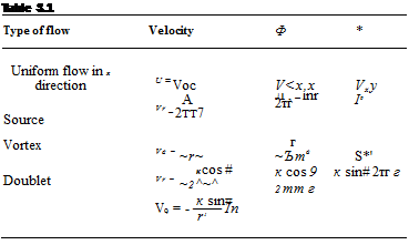
Подпись: Table 3.1 Type of flow Velocity Ф * Uniform flow in x direction U = Voc V<x,x Vxy Source A Vr _ 2TT7 Л , — lnr 2тг І9 Vortex Ve = ~r~ г ~Ътв S*' Doublet К cos # Vr = ~2^~^ к cos 9 2тт г к sin# 2тг г к sin# V9 = - —— In r1

1 Зф

Подпись: The stream function is determined in a similar manner: 0 Подпись:—- — = Vr

г Зв

Зф Г

dr в 2лг

Подпись: ф — — In r In Подпись: [3.114]

Integrating Equations (3.113а and b), we have

Equation (3.114) is the stream function for vortex flow. Note that since ф = constant is the equation of the streamline, Equation (3.114) states that the streamlines of vortex flow are given by r = constant (i. e., the streamlines are circles). Thus, Equation

(3.114) is consistent with our definition of vortex flow. Also, note from Equation (3.112) that equipotential lines are given by в = constant, that is, straight radial lines from the origin. Once again, we see that equipotential lines and streamlines are mutually perpendicular.

At this stage, we summarize the pertinent results for our four elementary flows in Table 3.1.

Prandtl—The Early Development of Finite-Wing Theory

On June 27, 1866, in a paper entitled “Aerial Locomotion” given to the Aeronautical Society of Great Britain, the Englishman Francis Wenham expressed for the first time in history the effect of aspect ratio on finite-wing aerodynamics. He theorized (correctly) that most of the lift of a wing occurs from the portion near the leading edge, and hence a long, narrow wing would be most efficient. He suggested stacking a number of long thin wings above each other to generate the required lift, and he built two full-size gliders in 1858, both with five wings each, to demonstrate (successfully) his ideas. (Wenham is also known for designing and building the first wind tunnel in history, at Greenwich, England, in 1871.)

However, the true understanding of finite-wing aerodynamics, as well as ideas for the theoretical analysis of finite wings, did not come until 1907. In that year, Frederick W. Lanchester published his now famous book entitled Aerodynamics. We have met Lanchester before—in Section 4.14 concerning his role in the development of the circulation theory of lift. Here, we examine his contributions to finite-wing theory.

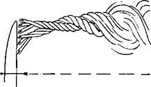
In Lanchester’s Aerodynamics, we find the first mention of vortices that trail downstream of the wing tips. Figure 5.46 is one of Lanchester’s own drawings from his 1907 book, showing the “vortex trunk” which forms at the wing tip. Moreover, he knew that a vortex filament could not end in space (see Section 5.2), and he theorized that the vortex filaments that constituted the two wing-tip vortices must cross the wing along its span—the first concept of bound vortices in the spanwise direction. Hence, the essence of the horseshoe vortex concept originated with Lanchester. In his own words:

Thus the author regards the two trailed vortices as a definite proof of the existence

of a cyclic component of equal strength in the motion surrounding the airfoil itself.

Considering the foresight and originality of Lanchester’s thinking, let us pause for a moment and look at the man himself. Lanchester was bom on October 23,1868,

image465

Figure 5.46 A figure from Lanchester’s Aerodynamics, 1 907; this is his own drawing of the wing-tip vortex on a finite wing.

in Lewisham, England. The son of an architect, Lanchester became interested in engineering at an early age. (He was told by his family that his mind was made up at the age of 4.) He studied engineering and mining during the years 1886-1889 at the Royal College of Science in South Kensington, London, but never officially graduated. He was a quick-minded and innovative thinker and became a designer at the Forward Gas Engine Company in 1889, specializing in internal combustion engines. He rose to the post of assistant works manager. In the early 1890s, Lanchester became very interested in aeronautics, and along with his development of high-speed engines, he also carried out numerous aerodynamics experiments. It was during this period that he formulated his ideas on both the circulation theory of lift and the finite-wing vortex concepts. A serious paper written by Lanchester first for the Royal Society, and then for the Physical Society, was turned down for publication—something Lanchester never forgot. Finally, his aeronautical concepts were published in his two books Aerodynamics and Aerodonelics in 1907 and 1908, respectively. To his detriment, Lanchester had a style of writing and a means of explanation that were not easy to follow and his works were not immediately seized upon by other researchers. Lanchester’s bitter feelings about the public’s receipt of his papers and books are graphically seen in his letter to the Daniel Guggenheim Medal Fund decades later. In a letter dated June 6, 1931, Lanchester writes:

So far as aeronautical science is concerned, I cannot say that I experienced any­thing but discouragement; in the early days my theoretical work (backed by a certain amount of experimental verification), mainly concerning the vortex theory of sus – tentation and the screw propeller, was refused by the two leading scientific societies in this country, and I was seriously warned that my profession as an engineer would suffer if I dabbled in a subject that was merely a dream of madmen! When I pub­lished my two volumes in 1907 and 1908 they were well received on the whole, but this was mainly due to the success of the brothers Wright, and the general interest aroused on the subject.

In 1899, he formed the Lanchester Motor Company, Limited, and sold automobiles of his own design. He married in 1919, but had no children. Lanchester maintained

his interest in automobiles and related mechanical devices until his death on March 8, 1946, at the age of 77.

In 1908, Lanchester visited Gottingen, Germany, and fully discussed his wing theory with Ludwig Prandtl and his student Theodore von Karman. Prandtl spoke no English, Lanchester spoke no German, and in light of Lanchester’s unclear way of explaining his ideas, there appeared to be little chance of understanding between the two parties. However, shortly after, Prandtl began to develop his own wing theory, using a bound vortex along the span and assuming that the vortex trails downstream from both wing tips. The first mention of Prandtl’s work on finite-wing theory was made in a paper by O. Foppl in 1911, discussing some of Foppl’s experimental work on finite wings. Commenting on his results, Foppl says:

They agree very closely with the theoretical investigation by Professor Prandtl on the current around an airplane with a finite span wing. Already Lanchester in his work, “Aerodynamics” (translated into German by C. and A. Runge), indicated that to the two extremities of an airplane wing are attached two vortex ropes (Wirbelzopfe) which make possible the transition from the flow around the airplane, which occurs nearly according to Kutta’s theory, to the flow of the undisturbed fluid at both sides. These two vortex ropes continue the vortex which, according to Kutta’s theory, takes place on the lamina.

We are led to admit this owing to the Helmholtz theorem that vortices cannot end in the fluid. At any rate these two vortex ropes have been made visible in the Gottingen Institute by emitting an ammonia cloud into the air. Prandtl’s theory is constructed on the consideration of this current in reality existing.

In the same year, Prandtl expressed his own first published words on the subject. In a paper given at a meeting of the Representatives of Aeronautical Science in Gottingen in November 1911, entitled “Results and Purposes of the Model Experimental Institute of Gottingen,” Prandtl states:

Another theoretical research relates to the conditions of the current which is formed by the air behind an airplane. The lift generated by the airplane is, on account of the principle of action and reaction, necessarily connected with a descending current behind the airplane. Now it seemed very useful to investigate this descending current in all its details. It appears that the descending current is formed by a pair of vortices, the vortex filaments of which start from the airplane wing tips. The distance of the two vortices is equal to the span of the airplane, their strength is equal to the circulation of the current around the airplane and the current in the vicinity of the airplane is fully given by the superposition of the uniform current with that of a vortex consisting of three rectilinear sections.

In discussing the results of his theory, Prandtl goes on to state in the same paper:

The same theory supplies, taking into account the variations of the current on the airplane which came from the lateral vortices, a relationship showing the depen­dence of the airplane lift on the aspect ratio; in particular it gives the possibility of extrapolating the results thus obtained experimentally to the airplane of infinite span wing. From the maximum aspect ratios measured by us (1:9 to that of 1 :oo) the lifts increase further in marked degree—by some 30 or 40 percent. I would add here a

remarkable result of this extrapolation, which is, that the results of Kutta’s theory of the infinite wing, at least so far as we are dealing with small cambers and small angles of incidence, have been confirmed by these experimental results.

Starting from this line of thought we can attack the problem of calculating the surface of an airplane so that lift is distributed along its span in a determined manner, previously fixed. The experimental trial of these calculations has not yet been made, but it will be in the near future.

It is clear from the above comments that Prandtl was definitely following the model proposed earlier by Lanchester. Moreover, the major concern of the finite-wing theory was first in the calculation of lift—no mention is made of induced drag. It is interesting to note that Prandtl’s theory first began with a single horseshoe vortex, such as sketched in Figure 5.11. The results were not entirely satisfactory. During the period 1911­1918, Prandtl and his colleagues expanded and refined his finite-wing theory, which evolved to the concept of a lifting line consisting of an infinite number of horseshoe vortices, as sketched in Figure 5.13. In 1918, the term “induced drag’’ was coined by Max Munk, a colleague of Prandtl at Gottingen. Much of Prandtl’s development of finite-wing theory was classified secret by the German government during World War I. Finally, his lifting-line theory was released to the outside world, and his ideas were published in English in a special NACA report written by Prandtl and published in 1922, entitled “Applications of Modern Hydrodynamics to Aeronautics” (NACA TR 116). Hence, the theory we have outlined in Section 5.3 was well-established more than 80 years ago.

One of Prandtl’s strengths was the ability to base his thinking on sound ideas, and to apply intuition that resulted in relatively straightforward theories that most engineers could understand and appreciate. This is in contrast to the difficult writ­ings of Lanchester. As a result, the lifting theory for finite wings has come down through the years identified as Prandtl’s lifting-line theory, although we have seen that Lanchester was the first to propose the basic model on which lifting-line theory is built.

In light of Lanchester’s 1908 visit with Prandtl and Prandtl’s subsequent de­velopment of the lifting-line theory, there has been some discussion over the years that Prandtl basically stole Lanchester’s ideas. However, this is clearly not the case. We have seen in the above quotes that Prandtl’s group at Gottingen was giving full credit to Lanchester as early as 1911. Moreover, Lanchester never gave the world a clear and practical theory with which results could be readily obtained—Prandtl did. Therefore, in this book we have continued the tradition of identifying the lifting-line theory with Prandtl’s name. On the other hand, for very good reasons, in England and various places in western Europe, the theory is labeled the Lanchester-Prandtl theory.

To help put the propriety in perspective, Lanchester was awarded the Daniel Guggenheim Medal in 1936 (Prandtl had received this award some years earlier). In the medal citation, we find the following words:

Lanchester was the foremost person to propound the now famous theory of flight based on the Vortex theory, so brilliantly followed up by Prandtl and others. He first

put forward his theory in a paper read before the Birmingham Natural History and Philosophical Society on 19th June, 1894. In a second paper in 1897, in his two books published in 1907 and 1908, and in his paper read before the Institution of Automobile Engineers in 1916, he further developed this doctrine.

Perhaps the best final words on Lanchester are contained in this excerpt from his obituary found in the British periodical Flight in March 1946:

And now Lanchester has passed from our ken but not from our thoughts. It is to be hoped that the nation which neglected him during much of his lifetime will at any rate perpetuate his work by a memorial worthy of the “Grand Old Man” of aerodynamics.

Fluid Statics: Buoyancy Force

In aerodynamics, we are concerned about fluids in motion, and the resulting forces and moments on bodies due to such motion. However, in this section, we consider the special case of no fluid motion, i. e., fluid statics. A body immersed in a fluid will still experience a force even if there is no relative motion between the body and the fluid. Let us see why.

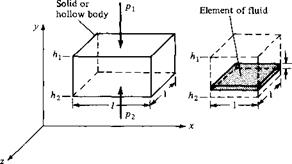
To begin, we must first consider the force on an element of fluid itself. Consider a stagnant fluid above the xz plane, as shown in Figure 1.31. The vertical direction is given by y. Consider an infinitesimally small fluid element with sides of length dx, dy, and dz. There are two types of forces acting on this fluid element: pressure forces from the surrounding fluid exerted on the surface of the element, and the gravity force due to the weight of the fluid inside the element. Consider forces in the у direction. The pressure on the bottom surface of the element is p, and hence the force on the bottom face is p(dx dz) in the upward direction, as shown in Figure

(p + ^dy)dx dz

image57

fluid.


1.31. The pressure on the top surface of the element will be slightly different from the pressure on the bottom because the top surface is at a different location in the fluid. Let dp/dy denote the rate of change of p with respect to y. Then the pressure exerted on the top surface will be p + (dp/dy) dy, and the pressure force on the top of the element will be [p + (dp/dy) dy](dx dz) in the downward direction, as shown in Figure 1.31. Hence, letting upward force be positive, we have

Net pressure force = p(dx dz) — ( p + —dy ) (dx dz)

dy J

= — — (dx dy dz) dy

Let p be the mean density of the fluid element. The total mass of the element is p(dx dy dz). Therefore,

Gravity force = —p(dx dy dz)g

where g is the acceleration of gravity. Since the fluid element is stationary (in equi­librium), the sum of the forces exerted on it must be zero:

Подпись: or Подпись: dp = ~gp dy Подпись: [1.52]

-—(dx dy dz) – gp(dxdydz) = 0 dy

Equation (1.52) is called the Hydrostatic equation; it is a differential equation which relates the change in pressure dp in a fluid with a change in vertical height dy.

The net force on the element acts only in the vertical direction. The pressure forces on the front and back faces are equal and opposite and hence cancel; the same is true for the left and right faces. Also, the pressure forces shown in Figure 1.31 act at the center of the top and bottom faces, and the center of gravity is at the center of the elemental volume (assuming the fluid is homogeneous); hence, the forces in Figure 1.31 are colinear, and as a result, there is no moment on the element.

Equation (1.52) governs the variation of atmospheric properties as a function of altitude in the air above us. It is also used to estimate the properties of other planetary atmospheres such as for Venus, Mars, and Jupiter. The use of Equation (1.52) in the analysis and calculation of the “standard atmosphere” is given in detail in Reference 2; hence, it will not be repeated here.

Let the fluid be a liquid, for which we can assume p is constant. Consider points 1 and 2 separated by the vertical distance Ah as sketched on the right side of Figure

1.31. The pressure and у locations at these points are pi, h, and /?2, hi. respectively. Integrating Equation (1.52) between points 1 and 2, we have

Г P2 rhl

dp = – pg dy J p J h

Подпись: [1.53]Подпись: orPi – Pi = ~Pg(hi — hj) — pg Ah

where Ah = h — hi. Equation (1.46) can be more conveniently expressed as

Подпись: or Подпись: p + pgh = constant Подпись: [1.54]

P2 + pgh2 = pi + pghi

Note that in Equations (1.53) and (1.54), increasing values of h are in the positive (upward) у direction.

A simple application of Equation (1.54) is the calculation of the pressure distri­bution on the walls of a container holding a liquid, and open to the atmosphere at the top. This is illustrated in Figure 1.32, where the top of the liquid is at a heght hi. The atmospheric pressure pa is impressed on the top of the liquid; hence, the pressure at h is simply pa. Applying Equation (1.54) between the top (where h = h) and an arbitrary height h, we have

P + Pgh = pі + pghi = pa+ Pgh і

or p = Pa + pg(h – h) [1.55]

Equation (1.55) gives the pressure distribution on the vertical sidewall of the container as a function of h. Note that the pressure is a linear function of h as sketched on the right of Figure 1.32, and that p increases with depth below the surface.

image58

Another simple and very common application of Equation (1.54) is the liquid – filled U-tube manometer used for measuring pressure differences, as sketched in Figure 1.33. The manometer is usually made from hollow glass tubing bent in the shape of the letter U. Imagine that we have an aerodynamic body immersed in an airflow (such as in a wind tunnel), and we wish to use a manometer to measure the surface pressure at point b on the body. A small pressure orifice (hole) at point b is connected to one side of the manometer via a long (usually flexible) pressure tube. The other side of the manometer is open to the atmosphere, where the pressure pa is a known value. The U tube is partially filled with a liquid of known density p. The tops of the liquid on the left and right sides of the U tube are at points 1 and 2, with heights h and h2, respectively. The body surface pressure pt, is transmitted through the pressure tube and impressed on the top of the liquid at point 1. The atmospheric pressure pa is impressed on the top of the liquid at point 2. Because in general рь ф pa, the tops of the liquid will be at different heights; i. e., the two sides of the manometer will show a displacement Ah = hi — h2 of the fluid. We wish to

The use of a U-tube manometer.

obtain the value of the surface pressure at point b on the body by reading the value of Ah from the manometer. From Equation (1.54) applied between points 1 and 2,

Pb + pghi = pa + pgh2

or Pb = Pa – pg{h – h2)

or pb = Pa – pg Ah [1.56]

In Equation (1.56), pa, p, and g are known, and Ah is read from the U tube, thus allowing рь to be measured.

At the beginning of this section, we stated that a solid body immersed in a fluid will experience a force even if there is no relative motion between the body and the fluid. We are now in a position to derive an expression for this force, henceforth called the buoyancy force. We will consider a body immersed in either a stagnant gas or liquid, hence p can be a variable. For simplicity, consider a rectangular body of unit width, length/, and height {h—h2), as shown in Figure 1.34. Examining Figure 1.34, we see that the vertical force F on the body due to the pressure distribution over the surface is

F = (p2~ pi)l(l) [1.57]

There is no horizontal force because the pressure distributions over the vertical faces of the rectangular body lead to equal and opposite forces which cancel each other. In Equation (1.57), an expression for p2 — p can be obtained by integrating the hydrostatic equation, Equation (1.52), between the top and bottom faces:

Подпись: Pg dy

image60

ГР2 phi ph

P2 ~ Pi = dp = — I pgdy = I

J pi J h і «/ hi

image61

Figure 1.34 Source of the buoyancy force on a body immersed in a fluid.


Substituting this result into Equation (1.57), we obtain for the buoyancy force

Подпись: F = K 1) / Jhh

pgdy [1.58]

2

Подпись: Pg dy
image62

Consider the physical meaning of the integral in Equation (1.58). The weight of a small element of fluid of height dy and width and length of unity as shown at the right of Figure 1.34 is pg dy (1)(1). In turn, the weight of a column of fluid with a base of unit area and a height (h — /12) is

which is precisely the integral in Equation (1.58). Moreover, if we place l of these fluid columns side by side, we would have a volume of fluid equal to the volume of the body on the left of Figure 1.34, and the weight of this total volume of fluid would be

l pgdy J /12

which is precisely the right-hand side of Equation (1.58). Therefore, Equation (1.58) states in words that

Buoyancy force

weight of fluid

on body

— displaced by body

We have just proved the well-known Archimedes principle, first advanced by the Greek scientist, Archimedes of Syracuse (287-212 B. C.). Although we have used a rectangular body to simplify our derivation, the Archimedes principle holds for bodies of any general shape. (See Problem 1.14 at the end of this chapter.) Also, note from our derivation that the Archimedes principle holds for both gases and liquids and does not require that the density be constant.

The density of liquids is usually several orders of magnitude larger than the density of gases; e. g., for water p = 103 kg/m3, whereas for air p = 1.23 kg/m3. Therefore, a given body will experience a buoyancy force a thousand times greater in water than in air. Obviously, for naval vehicles buoyancy force is all important, whereas for airplanes it is negligible. On the other hand, lighter-than-air vehicles, such as blimps and hot-air balloons, rely on buoyancy force for sustenation; they obtain sufficient buoyancy force simply by displacing huge volumes of air. For most problems in aerodynamics, however, buoyancy force is so small that it can be readily neglected.

A hot-air balloon with an inflated diameter of 30 ft is carrying a weight of 800 lb, which includes the weight of the hot air inside the balloon. Calculate (a) its upward acceleration at sea level the instant the restraining ropes are released and (b) the maximum altitude it can achieve. Assume that the variation of density in the standard atmosphere is given by p = 0.002377(1 — 7 x 10~6/t)4-21, where h is the altitude in feet and p is in slug/ft3.

Solution

(a) At sea level, where h = 0, p = 0.002377 slug/ft3. The volume of the inflated balloon is |я(15)3 = 14,137 ft3. Hence,

Buoyancy force = weight of displaced air

= gpV

where g is the acceleration of gravity and V is the volume.

Buoyancy force = В = (32.2)(0.002377)(14,137) = 1082 lb

The net upward force at sea level is F = В — W, where W is the weight. From Newton’s second law,

F = В — W = та

where m is the mass, m = Щ = 24.8 slug. Hence,

Подпись: 11.4 ft/s2Подпись: Example 1.8_ B-W 1082 – 800 a ~ m ~ 24Я

Подпись: P Подпись: В gv Подпись: 800 (32.2) (14,137) Подпись: 0.00176 slug/ft3

(b) The maximum altitude occurs when В = W = 800 lb. Since В = gpV, and assuming the balloon volume does not change,

From the given variation of p with altitude, h,

p = 0.002377(1 – 7 x 10~6/t)4-21 = 0.00176

Solving for h, we obtain

1

0.00176 1/4 21

h =————

1 – (————-

9842 ft

7 x 10~6

V 0.002377 j

Stream Function

In this section, we consider two-dimensional steady flow. Recall from Section 2.11 that the differential equation for a streamline in such a flow is given by Equation


image173

(2.118), repeated below

Подпись: [2.1 18] Equation (2.118) can be integrated Подпись:dy v dx и

If и and v are known functions of x and y, then to yield the algebraic equation for a streamline:

f(x, y) = c

where c is an arbitrary constant of integration, with different values for different streamlines. In Equation (2.139), denote the function of x and у by the symbol f. Hence, Equation (2.139) is written as

Подпись: [2.140]Ф(х, y)=C

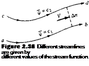
The function jr(x, y) is called the stream function. From Equation (2.140) we see that the equation for a streamline is given by setting the stream function equal to a constant, i. e., сі, c2, сз, etc. Two different streamlines are illustrated in Figure 2.38; streamlines ab and cd are given by jr = a and iJr = C2, respectively.

There is a certain arbitrariness in Equations (2.139) and (2.140) via the arbitrary constant of integration c. Let us define the stream function more precisely in order to reduce this arbitrariness. Referring to Figure 2.38, let us define the numerical value of іJr such that the difference AiJr between f = ci for streamline cd and jr = c for streamline ab is equal to the mass flow between the two streamlines. Since Figure 2.38 is a two-dimensional flow, the mass flow between two streamlines is defined per unit depth perpendicular to the page. That is, in Figure 2.38 we are considering the mass flow inside a streamtube bounded by streamlines ab and cd, with a rectangular cross­sectional area equal to An times a unit depth perpendicular to the page. Here, An is the normal distance between ab and cd, as shown in Figure 2.38. Hence, mass flow between streamlines ab and cd per unit depth perpendicular to the page is

Ді/r = C2 — Ci [2.141]

Подпись: Figure 2.38 Different streamlines are given by different values of the stream function.

The above definition does not completely remove the arbitrariness of the constant of integration in Equations (2.139) and (2.140), but it does make things a bit more precise. For example, consider a given two-dimensional flow field. Choose one streamline of the flow, and give it an arbitrary value of the stream function, say, fr = a. Then, the value of the stream function for any other streamline in the flow, say, fr = сг,

is fixed by the definition given in Equation (2.141). Which streamline you choose to designate as ф = c and what numerical value you give c usually depend on the geometry of the given flow field, as we see in Chapter 3.

The equivalence between ф = constant designating a streamline, and Аф equal­ing mass flow (per unit depth) between streamlines, is natural. For a steady flow, the mass flow inside a given streamtube is constant along the tube; the mass flow across any cross section of the tube is the same. Since by definition Д ф is equal to this mass flow, then Аф itself is constant for a given streamtube. In Figure 2.38, if ф = C designates the streamline on the bottom of the streamtube, then ф2 = <"2 = c + Аф is also constant along the top of the streamtube. Since by definition of a streamtube (see Section 2.11) the upper boundary of the streamtube is a streamline itself, then ф2 = C2 = constant must designate this streamline.

We have yet to develop the most important property of the stream function, namely, derivatives of ф yield the flow-field velocities. To obtain this relationship, consider again the streamlines a b and cd in Figure 2.38. Assume that these streamlines are close together (i. e., assume An is small), such that the flow velocity V is a constant value across An. The mass flow through the streamtube per unit depth perpendicular to the page is

Подпись: [2.142]Подпись: [2.143]Подпись:Аф = pV An(l) Аф

~^=PV

An

Consider the limit of Equation (2.142) as An —» 0:

,, r АФ H

pV = lim ——— = —

An->0 An dn

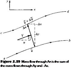
Equation (2.143) states that if we know ф, then we can obtain the product (p V) by differentiating ф in the direction normal to V. To obtain a practical form of Equation (2.143) for cartesian coordinates, consider Figure 2.39. Notice that the directed normal distance An is equivalent first to moving upward in the у direction by the amount Ay and then to the left in the negative x direction by the amount — Ax. Due to conservation of mass, the mass flow through An (per unit depth) is equal to the sum of the mass flows through Ay and — Ax (per unit depth):

Mass flow = Аф = pV An = pu Ay + pv(-Ax) [2.144]

Letting cd approach ab, Equation (2.144) becomes in the limit

d’ijf = pudy — pvdx [2.145]

However, since ф = ф (x, y), the chain rule of calculus states

– 3 ф 3 ф

dф = —dx H——- dy [2.146]

dx dy

Comparing Equations (2.145) and (2.146), we have
[2.147a]

image175"

Подпись: Figure 2.39 Mass flow through An is the sum of the mass flows through Ay and - Ax.

[2.147b]

Equations (2.147a and b) are important. If ф(х, y) is known for a given flow field, then at any point in the flow the products pu and pv can be obtained by differentiating ф in the directions normal to и and v, respectively.

Stream Function Подпись: [2.148a] [2.148b]

If Figure 2.39 were to be redrawn in terms of polar coordinates, then a similar derivation yields

Such a derivation is left as a homework problem.

Note that the dimensions of ф are equal to mass flow per unit depth perpendicular to the page. That is, in SI units, ф is in terms of kilograms per second per meter perpendicular to the page, or simply kg/(s ■ m).

The stream function ф defined above applies to both compressible and incom­pressible flow. Now consider the case of incompressible flow only, where p = con-

stant. Equation (2.143) can be written as

Подпись:д(Ф/р)

dn

We define a new stream function, for incompressible flow only, as 1jr = i// /p. Then Equation (2.149) becomes

ЗіIr V = ~ dn

and Equations (2.147) and (2.148) become

image177[3.150a]

[3.150b]

and

image178[3.151a] [3.151b]

The incompressible stream function ф has characteristics analogous to its more gen­eral compressible counterpart iJr. For example, since ф(х, у) = c is the equation of a streamline, and since p is a constant for incompressible flow, then 1(r{x, y) = ф jp = constant is also the equation for a streamline (for incompressible flow only). In addition, since Д ф is mass flow between two streamlines (per unit depth perpendic­ular to the page), and since p is mass per unit volume, then physically Аф = Ді]r/p represents the volume flow (per unit depth) between two streamlines. In SI units, Аф is expressed as cubic meters per second per meter perpendicular to the page, or simply m2/s.

In summary, the concept of the stream function is a powerful tool in aerodynam­ics, for two primary reasons. Assuming that ф(х, y) [or ф(х, y)[ is known through the two-dimensional flow field, then:

1. ф = constant (or ф = constant) gives the equation of a streamline.

2. The flow velocity can be obtained by differentiating ф (or ф), as given by Equa­tions (2.147) and (2.148) for compressible flow and Equations (2.150) and (2.151) for incompressible flow. We have not yet discussed how ф(х, y) [or ф(х, у)] can be obtained in the first place; we are assuming that it is known. The ac­tual determination of the stream function for various problems is discussed in Chapter 3.

The Kutta Condition

The lifting flow over a circular cylinder was discussed in Section 3.15, where we ob­served that an infinite number of potential flow solutions were possible, corresponding to the infinite choice of Г. For example, Figure 3.28 illustrates three different flows over the cylinder, corresponding to three different values of Г. The same situation applies to the potential flow over an airfoil; for a given airfoil at a given angle of attack, there are an infinite number of valid theoretical solutions, corresponding to an

3 It is interesting to note that some recent research by NASA is hinting that even as complex a problem as flow separation, heretofore thought to be a completely viscous-dominated phenomenon, may in reality be an inviscid-dominated flow which requires only a rotational flow. For example, some inviscid flow-field numerical solutions for flow over a circular cylinder, when vorticity is introduced either by means of a nonuniform freestream or a curved shock wave, are accurately predicting the separated flow on the rearward side of the cylinder. However, as exciting as these results may be, they are too preliminary to be emphasized in this book. We continue to talk about flow separation in Chapters 15 to 20 as being a viscous-dominated effect, until definitely proved otherwise. This recent research is mentioned here only as another example of the physical connection between vorticity, vortex sheets, viscosity, and real life.

infinite choice of Г. For example, Figure 4.12 illustrates two different flows over the same airfoil at the same angle of attack but with different values of Г. At first, this may seem to pose a dilemma. We know from experience that a given airfoil at a given angle of attack produces a single value of lift (e. g., see Figure 4.5). So, although there is an infinite number of possible potential flow solutions, nature knows how to pick a particular solution. Clearly, the philosophy discussed in the previous section is not complete—we need an additional condition that fixes Г for a given airfoil at a given a.

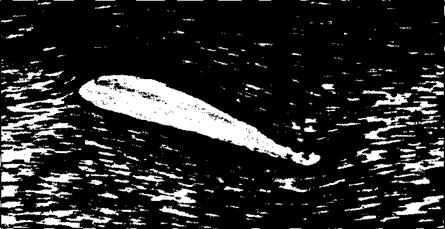
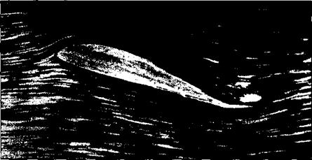
To attempt to find this condition, let us examine some experimental results for the development of the flow field around an airfoil which is set into motion from an initial state of rest. Figure 4.13 shows a series of classic photographs of the flow over an airfoil, taken from Prandtl and Tietjens (Reference 8). In Figure 4.13a, the flow has just started, and the flow pattern is just beginning to develop around the airfoil. In these early moments of development, the flow tries to curl around the sharp trailing edge from the bottom surface to the top surface, similar to the sketch shown at the left of Figure 4.12. However, more advanced considerations of inviscid, incompressible flow (see, e. g., Reference 9) show the theoretical result that the velocity becomes infinitely large at a sharp comer. Hence, the type of flow sketched at the left of Figure 4.12, and shown in Figure 4.13a, is not tolerated very long by nature. Rather, as the real flow develops over the airfoil, the stagnation point on the upper surface (point 2 in Figure 4.12) moves toward the trailing edge. Figure 4.13b shows this intermediate stage. Finally, after the initial transient process dies out, the steady flow shown in Figure 4.13c is reached. This photograph demonstrates that the flow is smoothly leaving the top and the bottom surfaces of the airfoil at the trailing edge. This flow pattern is sketched at the right of Figure 4.12 and represents the type of pattern to be expected for the steady flow over an airfoil.

Reflecting on Figures 4.12 and 4.13, we emphasize again that in establishing the steady flow over a given airfoil at a given angle of attack, nature adopts that particular value of circulation (Г2 in Figure 4.12) which results in the flow leaving smoothly at the trailing edge. This observation was first made and used in a theoretical analysis by the German mathematician M. Wilhelm Kutta in 1902. Therefore, it has become known as the Kutta condition.

image314

Figure 4.12 Effect of different values of circulation on the potential flow over a given airfoil at a given angle of attack. Points 1 and 2 are stagnation points.

image315

(a)

image316

(b)

Figure 4.1 3 The development of steady flow over an airfoil; the airfoil is impulsively started from rest and attains a steady velocity through the fluid, (a) A moment just after starting, (b) An intermediate time. (Source: Prandtl and Tiejens, Reference 8.)

In order to apply the Kutta condition in a theoretical analysis, we need to be more precise about the nature of the flow at the trailing edge. The trailing edge can have a finite angle, as shown in Figures 4.12 and 4.13 and as sketched at the left of Figure 4.14, or it can be cusped, as shown at the right of Figure 4.14. First, consider the trailing edge with a finite angle, as shown at the left of Figure 4.14. Denote the velocities along the top surface and the bottom surface as V and to, respectively. Vt

image317

(f)

Figure 4.1 3 (continued) The development of steady flow over an airfoil; the airfoil is

impulsively started from rest and attains a steady velocity through the fluid, (c) The final steady flow. (Source: Prandtl and Tiejens, Reference 8.)


Finite angle Cusp

image318

At point a, Kj = V2 = 0 At point a: V1 = V2 Ф 0

Figure 4.1 4 Different possible shapes of the trailing edge and their relation to the Kutta condition.


is parallel to the top surface at point a, and V2 is parallel to the bottom surface at point a. For the finite-angle trailing edge, if these velocities were finite at point a, then we would have two velocities in two different directions at the same point, as shown at the left of Figure 4.14. Flowever, this is not physically possible, and the only recourse is for both Vj and V2 to be zero at point a. That is, for the finite trailing edge, point a is a stagnation point, where Vj = V2 = 0. In contrast, for the cusped trailing edge shown at the right of Figure 4.14, V and V2 are in the same direction at point a, and hence both Vj and V2 can be finite. Flowever, the pressure at point a, p2, is a single, unique value, and Bernoulli’s equation applied at both the top and bottom surfaces immediately adjacent to point a yields

Pa + pV i2 = Pa + pV2

Подпись:Vj = F2

Hence, for the cusped trailing edge, we see that the velocities leaving the top and bottom surfaces of the airfoil at the trailing edge are finite and equal in magnitude and direction.

We can summarize the statement of the Kutta condition as follows:

1. For a given airfoil at a given angle of attack, the value of Г around the airfoil is such that the flow leaves the trailing edge smoothly.

2. If the trailing-edge angle is finite, then the trailing edge is a stagnation point.

3. If the trailing edge is cusped, then the velocities leaving the top and bottom surfaces at the trailing edge are finite and equal in magnitude and direction.

Consider again the philosophy of simulating the airfoil with vortex sheets placed either on the surface or on the camber line, as discussed in Section 4.4. The strength of such a vortex sheet is variable along the sheet and is denoted by у (і). The statement of the Kutta condition in terms of the vortex sheet is as follows. At the trailing edge (ТЕ), from Equation (4.8), we have

У (ТЕ) = y(a) = V1- V2 [4.9]

However, for the finite-angle trailing edge, V = V2 = 0; hence, from Equation (4.9), у (ТЕ) = 0. For the cusped trailing edge, V = V2 Ф 0; hence, from Equation (4.9), we again obtain the result that у (ТЕ) = 0. Therefore, the Kutta condition expressed in terms of the strength of the vortex sheet is

[4.10]

First Law of Thermodynamics

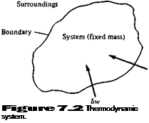
Подпись: Figure 7.2 Thermodynamic system.

Consider a fixed mass of gas, which we define as the system. (For simplicity, assume a unit mass, for example, 1 kg or 1 slug.) The region outside the system is called the surroundings. The interface between the system and its surroundings is called the boundary, as shown in Figure 7.2. Assume that the system is stationary. Let Sq be an incremental amount of heat added to the system across the boundary, as sketched in Figure 7.2. Examples of the source of 8q are radiation from the surroundings which is absorbed by the mass in the system and thermal conduction due to temperature gradients across the boundary. Also, let 8 w denote the work done on the system by the surroundings (say, by a displacement of the boundary, squeezing the volume of the system to a smaller value). As discussed earlier, due to the molecular motion of the gas, the system has an internal energy e. The heat added and work done on the system cause a change in energy, and since the system is stationary, this change in

Sq + Sw = de

Подпись: [7.1 I]This is the first law of thermodynamics: It is an empirical result confirmed by experi­ence. In Equation (7.11), e is a state variable. Hence, de is an exact differential, and its value depends only on the initial and final states of the system. In contrast, Sq and Sw depend on the process in going from the initial to the final states.

For a given de, there are in general an infinite number of different ways (pro­cesses) by which heat can be added and work done on the system. We are primarily concerned with three types of processes:

1. Adiabatic process. One in which no heat is added to or taken away from the system

2. Reversible process. One in which no dissipative phenomena occur, that is, where the effects of viscosity, thermal conductivity, and mass diffusion are absent

3. Isentropic process. One that is both adiabatic and reversible

For a reversible process, it can be easily shown that Sw = —pdv, where dv is an incremental change in the volume due to a displacement of the boundary of the system. Thus, Equation (7.11) becomes

Подпись: [7.12]Sq — p dv = de