Category Fundamentals of Modern Unsteady Aerodynamics

Supersonic Kernel Method

We have seen the kernel function method for subsonic flows. Now, we are going to use a similar approach to develop supersonic kernel method based on the accel­eration potential. The relation between the acceleration potential and the velocity potential for simple harmonic motion was

W = іюф + U фx

and its solution was

x
ф = 1 e-ixx/U j W(k, y, z)eixk/Udk

The acceleration potential was related to the lifting pressure and it was in the following form

W = A°eix[t-M(x-n)/ab2±R/ab2]/R, R =l(x – П)2 – b2[(y – g)2 + z2]

oz v

For the velocity potential we can write

Подпись: ф _ A°e-ix(x-n)/U f eix(t+l/U-Ml/ap2+R/ap2)dk ф A0ze J e R x-n

Supersonic Kernel Method

0 –

Подпись:Подпись: A

Supersonic Kernel Method

Here, L(n, g) is the unknown lifting pressure at the wing surface. In supersonic flow, we know that the acceleration potential is affected by two different wave front to give the solution in following form

Подпись: ei(xt-M2rnximage114) cos(M—)

R

The supersonic kernel method is based on the numerical solution of a matrix system formed with finite number of points taken for the integral equation written above. It is applicable to the wing geometries having subsonic leading edges and supersonic trailing edges. The matrix system formed by the numerical integration is difficult to invert, however, with proper choice of pressure modes it becomes invertible (Cunningham 1966).

Mach Box Method

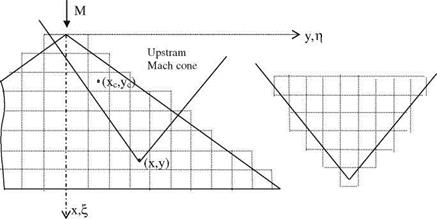
Mach Box Method is based on subdivision of the surface of the thin wing in a supersonic flow into small square boxes and summing the effect of all these boxes, as shown in Fig. 5.16, if all the edges of the wing are supersonic (Landahl and

image111

Fig. 5.16 Mach Boxes on a delta wing and its Mach cone

Stark). In addition, if there are subsonic edges present using the concept of dia­phragm, it can be applied to more general cases. First, as shown in Fig. 5.16, let us see its application on a delta wing with all supersonic edges. The boxes in the upstream Mach cone of point (x, y) have influence on the point (x, y) being the center of any square box on the wing surface. Let the jth box with the center coordinates (xc, yc) on wing has its vertical displacement as hj, pitch angle a,-, and roll angle 0j. The total displacement effect of the jth box on any point (x, y) reads as

Zj(x, y, t) = ~[hj{xc, Ус) + (x – xc)aj(xc, yc) + (y – yj)0j(xc, yc)]eixt

The boundary condition at the surface becomes

w(x, y, t) = — i<nhj + ia>(x — xc)aj + ix(y — yj)0j + Uaj]eixt. (5.87)

Choosing the equally sized boxes small enough, the downwash for the jth box reads as

Wj = —(tXhj + Uaj)eixt = Wjeixt (5.88)

Подпись: CPa (x ; У ) Подпись: V Mach Box Method

The amplitude of the lifting pressure coefficient was given in Eq. 5.86 in terms of downwash. If we sum the effect of all boxes influencing any point (x*, y*) on the wing surface the lifting pressure coefficient in summation notation reads as

Equation 5.89 is an expression with all complex elements. If it is written for all the boxes on the wing surface it will result in the following complex matrix equation.

К } =-4[R + ilfw} (5.90 — a)

p

Подпись: Rj + iIj = [ik + 0x* Mach Box Method

Here, the complex matrix [Rj + ij is the pressure influence coefficient matrix whose elements are the induced velocity at a point (x*, y*) of box Vj.

V

The elements of this complex matrix depend only on the reduced frequency and the Mach number. Once the matrix is composed it can be used for all wing geometry which has supersonic edges. The lifting pressure coefficient at any point (x*, y*) on the surface can be evaluated without inversion of any matrix, i. e. explicitly as follows

While we are developing the Mach box technique we assumed that the lower and the upper surfaces of the wing do not interact with each other. This assumption

holds if all edges of the wing is supersonic, since only for the supersonic edges no information can be carried from one surface to another. The picture, on the other hand, is different for the subsonic edges. The surface between the outside of the leading edge of a subsonic edge and the Mach cone is called the diaphragm surface, Fig. 5.17.

On the surface of diaphragm there is downwash with unknown value wd, but there is no lifting pressure. This gives us the opportunity of partitioning Eq. 5.90 as follows (Hassig et al. 1969).

image112(5.91)

Here,

Pww: Influence coefficient matrix of the wing on itself, square matrix Pwd- Influence coefficient matrix of the diaphragm on the wing,

PdW Influence coefficient matrix of the wing on the diaphragm,

Pdd’- Influence coefficient matrix of the diaphragm on itself, square matrix.

We can solve for the downwash value of the diaphragm using the second line of Eq. 5.91 as follows.

fWd } = -[Pdd ] 1[Pdw]{w }

and substituting the result in 5.91 gives us the desired lifting pressure coefficient.

Подпись: (5.92){Cpa } = ([Pww] – [Pwd ][Pdd ] 1[Pdw^{W}

Подпись:Подпись: diaphragmimage113

Mach Box Method

Fig. 5.17 Subsonic edge and the diaphragm

> y

x у

We have mentioned before that there is another method for solving the supersonic flow past thin wings. That was ‘Supersonic Kernel Function Method’. We are going to study that method next.

Supersonic Flow About Thin Wings

Equation 5.67 is given for the three dimensional velocity potential of a finite wing in a supersonic flow. Let us use this expression and the experiences we have had in handling the two dimensional supersonic flow to obtain the downwash expression.

Supersonic Flow About Thin Wings Supersonic Flow About Thin Wings Подпись: dO i=i (5.80)

For this purpose we take the derivative of the integral expression 5.67 with respect to z using Leibnitz rule.

The derivative of the first term of 5.80 reads as

0 Z „0A(n, g)

А(П y + g0 cos O) = — cos O 0Z g0 0g

The second term is given by Eq. 5.70. For the multipliers of the third term we take П = П1, t1 = t2 to obtain

=Tb; A(n У + gocos h)n=n1 = A(n1; y);

(eixT1 + eixT2 )£= n = 2eix(t^iai)

Supersonic Flow About Thin Wings

The third term now becomes enterable, and we finally have for the downwash

In Eq. 5.67, the unknown source strength was A(x, y). If we use the downwash expression, 5.82, in Eq. 5.67 we obtain an integral expression for the unknown potential in terms of the boundary condition

Подпись: 1n1 p

/u, i(x, y, Z, t) = T2pb wи, і(П, y + go cos O) (e‘“T1 + e‘“T2)dn dO (5.83)

00

The exponents of 5.83 can be written Cartesian coordinates to give the fol­lowing expression for the potential

_ і П }2 e-ix^{x-n) cos Щ

фи,1(Х; У Z)=T – g) R – dn dg (5-84)

0 g1

Supersonic Flow About Thin Wings

If you use the same nondimensional variables used for the two dimensional case, the amplitude of the velocity potential reads as

We know the relation between the lifting pressure and the velocity potential. Using that relation we obtain

(x‘;y,) = –(<k + о0*) //" fl/°S<~>dn‘ dg* (5.86)

V

Here, the area integral V is the intersection between the wing surface and the upstream Mach cone, and R reads as

R* = /(x*- П*)2-Ь2(у*- П*)2.

In this section, we have obtained the analytical relation for the lifting pressure coefficient as Eq. 5.86. We observe that for two and three dimensional supersonic flows the lifting pressure coefficient can be explicitly obtained from the downwash given at the surface as the boundary condition. This implies, unlike for the case of subsonic flows, determination of the surface pressure discontinuity does not require calculated inversion of an integral equation. Instead, the lifting pressure is computed with direct integration of 5.79 and 5.86.

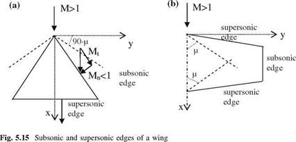
There are two different approaches in calculating the aerodynamic coefficients. The first method uses the analytical approach to calculate these coefficients for special geometries like delta wings. This method is good for rigid body motions like translation and rotation of wings (Miles 1959). The second approach is applicable to wider range of problems and they are approximate numerical methods. There are two different types of numerical methods. The first method is called ‘The Supersonic Kernel Function Method’, and the second one is the ‘Mach Box Method’. Before studying these methods in detail, we have to classify the wing edges as subsonic or supersonic edges. The criteria to decide about the type of the edge depend on the relation between the sweep angle and the Mach angle as indicated in Fig. 5.15.

In Fig. 5.15-a for the delta wing lying in the Mach cone of the flow, the component of the Mach number normal to the leading edge is less than 1,

image110

therefore, the leading edge shown is subsonic. On the other hand, the normal component of the Mach number at the trailing edge is greater than 1, therefore the trailing edge is supersonic. In Fig. 5.15b, only subsonic edge is the tip because the normal component of the Mach number is zero, whereas the leading and the trailing edges are outside of Mach cone and this makes those edges supersonic.

Supersonic Flow About a Profile

In a supersonic flow any point in the flowfield is affected by the points lying inside of its upstream Mach cone. For this reason, unlike subsonic flow, even for a wing with infinitely long span we have to consider the three dimensional problem. This means, two dimensional analysis of a supersonic external flow cannot take into consideration the true physical behavior of a lifting surface while calculating its aerodynamic coefficients. However, for academic purposes, we are going to treat a wing section as a two dimensional flow case and obtain the lifting pressure coefficient for the sake of demonstrating the integrations involved in the process.

In a two dimensional flow the source strength remains constant in spanwise direction. For this reason the velocity potential 5.67 can be expressed as follows.

n1 p

/(x, z, 0=b A(n) (eixs1 + eixs2 )dh dn,

image106

b 0 0 (5.68)

We can find the downwash expression by differentiating Eq. 5.68 with respect to z using the Leibnitz rule as follows.

П1 P P

= b A(n)J! Z(eixS1 + eixs2)d0dn + b0|а(П1) / (eixs1 + eixs2)dd

0 0 0

(5.69)

First term of right hand side of 5.69 as inner integral becomes

(eixs1 + eixs2) = ™ sin 0Og0(eixS1 _ eixs2) = sin e(eixT1 _ eixs2) (5.70)

Supersonic Flow About a Profile Подпись: t-aM2(x_n1 Подпись: (5.71)

The second term of 5.69, using the fact that, for П = П1, go = 0 and s1 = s2,

The relation 5.64 stated that depending on (x, y, z) being at the upper or lower surface of the wing we have (П1)и1 = x ^ b z.

Подпись: '0П1 0z Подпись: u,l Подпись: ^b and Supersonic Flow About a Profile Подпись: 2ei Подпись: (5.72)

By differentiation we obtain

We observe from 5.72 that the second integral of 5.69 is independent of в to give

?1 p

(дф = irnz _ eimi) s. n ^T 2 pA(n1)e,’“(tTiMbz) (5.73)

Подпись: 0 0z u i ab2 Па

Supersonic Flow About a Profile Подпись: (5.74)

Taking the limits for 5.73 for lower and upper surfaces the downwash value becomes

Using 5.74 in 5.73 gives us the velocity potential value as follows

6

Подпись: Фu,i(x, t) = ^2ppj Wu,i(0 J (eixT1 + eixs2)dhdn (5.75)

Подпись: 00

In order to integrate 5.75, the integrand of the inner integral must be function of в only. We can write the integrand as follows

Supersonic Flow About a Profile Подпись: (5.76)

p

p

J0(z) = ■ cos(z sin h)dh

p

0

Supersonic Flow About a Profile Подпись: t_M-2(X_n) Подпись: Jo(—f) * Подпись: (5.77)

and it gives us the velocity potential as

We need to express Eq. 5.77 in nondimensional form while obtaining the lifting pressure coefficient for a thin airfoil. Here, we use the following nondimensional quantities

n* = n/b, n* = n/b, k = b—/U, – = kM2/b2

Подпись: /u,l(X; t) Подпись: n; У Wu,i(n)e 0 Supersonic Flow About a Profile Подпись: -Pno M Подпись: dn* Подпись: (5.78)

This results in following expression for the velocity potential

We know the pressure coefficient in terms of the velocity potential. For a simple harmonic motion the amplitude of the pressure coefficient in terms of the velocity potential reads as

Подпись: P - Pi 1/2Pi U2
image107
Подпись: PP

Since the difference between the lower upper surface pressures gives the lifting pressure if we use Eq. 5.78 without the thickness effect, the lifting pressure coefficient

frequency of 0.20 obtain the amplitude of lifting pressure coefficient for simple harmonically heaving airfoil with amplitude p*.

Solution: With the aid of Mathematica the real and the imaginary parts of Eq. 5.79 can be evaluated along the chord using numerical integration. The graphs of real and imaginary parts of the lifting pressure are plotted below.

Подпись:Cpa Imaginery Part of Cpa

x

Supersonic Flow About a Profile Подпись: -0.2 -0.4 -0.6 -0.8 -1
Подпись: (a) real part
Подпись: *

0.2 0.4 0.6 0.8 1

The integral of the real and imaginary parts give the amplitude of the sectional lift coefficient in terms of the heave amplitude as follows.

Pei = (-0.055883 – 0.705385i)P*.

Unsteady Supersonic Flow

The linearized potential flow equations are exactly the same for the subsonic and supersonic flows. Equation 2.24 in its original open form was obtained as

This time we can use b2 = M2 — 1 as a parameter and perform a new Lorentz type of transformation (Miles 1959) to obtain the classical wave equation for the perturbation potential. Let us see the transformation based on a complex variables.

Подпись:Подпись: (5.57)x = x, у = ifiy, z = ibz and t = t — Mx/ab2, b = v2M2 — 1 In transformed coordinates the potential equation reads as

Подпись:

image102
Подпись: (2.24)
Подпись: = 0

1 02/

a2b4 0X2

t—-[1]!(Mx±g)

Подпись: /(X; У; Z; t) Подпись: ix /e Подпись: /R, Подпись: R Подпись: x2 — b2(y2 + z2) Подпись: (5.58)

The solution of 5.57 in original coordinates reads as

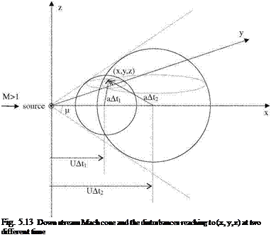
Подпись: Fig. 5.13 Down stream Mach cone and the disturbances reaching to (x, y, z) at two different time

The mathematical solution given with 5.58 is the expression for a source term in a supersonic flow. The ± appearing in exponent of 5.58 indicates that there are two different solutions for source. In order to identify the source solution which reflects the physics of the problem, we have to study the propagation of a dis­turbance in a supersonic flow as shown in Fig. 5.13. The speed of a wave front of a

perturbation in a supersonic flow placed at the origin is faster than the free stream. Therefore, the wave front is carried down in the direction of the free stream only in the positive x axis. For this reason, the tangent drawn from origin to the front surface at any time t makes a constant acute angle with the x axis as shown in Fig. 5.13. The locus of all these tangent lines is a conical surface called the Mach cone. The cone which is symmetric of this cone with respect to y-z plane is called the upstream Mach cone, and the opposite one is called the downstream Mach cone. Let At denote the time between its introduction to the flow and the present time t. If we call the half angle of the Mach cone as i = Mach angle, then we have

a At _ ( 1

sin i and i = sin

r U At MJ

Now, we can comment on the physics of the problem via Fig. 5.13. The comment will be based on the kinematic entities such as the free stream speed and the propagation speed of a disturbance placed in the flowfield. Knowing that the disturbance front travel as an expanding spherical surface, we can analyze the conditions under which the spherical front reaches at an arbitrary point (x, y, z) of the flowfield.

As seen in Fig. 5.13, there are two different spherical surfaces which pass through point (x, y, z). Both of these spherical surfaces are the products of the same disturbance created at the origin at time s and felt at the point (x, y, z) at two different times t1 and t2. With these timings the elapsed times are measured as A t1 = t1 — s and A t2 = t2 — s. The point (x, y, z), first feels the disturbance at time t1 from the frontal side, and at later time t2 the same point is effected by the back side of the disturbance. In other words, at the same instant t, point (x, y, z) feels the effect of two different disturbances created at the origin at two different times s1 and s2. This time, the durations elapsed between the creation of the disturbances and the present time t reads as Atj = t — sj and At2 = t — s2. In both cases, point (x, y, z) lies in the Mach cone. Any point outside of Mach cone does not feel any disturbance, therefore that region is called the zone of silence. Now, we can obtain the relations between the relevant timings using Fig. 5.13 and the interpretations made above.

a(t — s1)= [x — U(t — s1 )]2 + y2 + z2

(5.59 — a, b)

a(t — s2)= [U(t — s2)—x]2 + y2 + z2

From 5.59-a, b we can solve for sj and s2 as follows.

s1 = t—— ^(Mx — R) (5.60 — a, b)

ab 1

Considering the chronological order of the timings we have t > s1 > s2. We have also obtained the solution for the potential of the supersonic flow with expression 5.58. If we want to obtain a continuous solution in time, we have to include both of the solutions of 5.60-a, b for our perturbation potential as follows

/(x, y, z, t)=/(eixT1 + eixs2)/R. (5.61)

The solution we have obtained with 5.61 is going to be used as continuously distributed sources over the x-y plane to simulate the lifting surfaces undergoing simple harmonic motions. This distributed source has unknown distributed strength over the planform but in time it will oscillate simple harmonically. On the other hand, since the flow is supersonic, any point (x, y, z) in the flowfield is affected only from the points which are in its upstream Mach cone. We can now, write the integral expression accounting for all surface disturbances for the velocity potential as follows

/(x, y, z, t) = jjА(П, g)[(eixs1 + eixs2)/R]d£ dg (5.62)

V

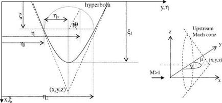
Here, А(П, g) is the unknown amplitude of the distributed source. The area over which the integral to be evaluated is a hyperbola defined as the intersection of the x-y plane with the upstream Mach cone of point (x, y, z), i. e. R = 0. This means, while z approaches zero we need to satisfy (x — П)2 – b2(y — g)2 — z2 = 0, which in turn means, it gives an equation of a hyperbola on x-y plane, because inter­section of a cone with a plane parallel to its axis is an hyperbola. The hyperbola and the pertinent geometric variables are shown in Fig. 5.14. The lower and upper integration limits for the double integral of Eq. 5.62 shown in Fig. 5.14 are defined as g1 and g2 as follows.

image104

Fig. 5.14 Upstream Mach cone, and the integration area V

The integral limits in the chord direction can be considered as follows. We take the П = 0 point as the lower limit, and the apex of the hyperbola as the upper limit. Equation 5.63 tells us that g1 = g2 is the point for the upper limit, where the term under square root must be zero. That gives us

П1 = x ± b z (5.64)

Here, according to Fig. 5.14 x > П1, therefore in Eq. 5.64, +z is used for the lower surface, and —z is used for the upper surface. This information will be useful for evaluation of lifting pressure as lower minus upper surface pressure distributions.

Knowing the upper and lower limits of the integral 5.62, we can express

І1 g2

/(x, y, z, {) = J J А(П; g)[(e‘“T1 + e‘“T2)/Rdndg (5.65)

0 g1

Here, the exponents read as

S1,2 = t – 2[M(x – П)Т R)] and R = (x – П)2 – b2(y – g)2 + b2z2.

ap

(5.66 – a, b)

Values for g1 and g2 are used to give us R = by/(g – g1 )(g2 – g). In spanwise direction, as shown in Fig. 5.14, if we use variable в we obtain 2g = (g2 — g1)cosh + g2 + g1. With this transformation, and defining go = (g2 — g1)/2 gives us

dg = —go sin hdh and R = bgo sin в

Here, again according to Fig. 5.14, в = p at g = g1, and в = 0 at g = g2 . If we rewrite integral 5.65 in terms of new variables, it becomes

n1 p

Подпись:

image105

/(x, y, z, t) =p А(П, y + go cos в)(е‘“Т1 + e‘“T2)dn dh,

00

S1,2 = t – 2[M(x – n)Tbgo sin в]

ab2

The velocity potential given by 5.67 is differentiated with respect to z to obtain the downwash at the wing surface. First, let us employ 5.67 to study the supersonic flow past a profile.

Supersonic Flow

In a compressible flow if the local speeds of air particles exceed the local speed of sound, the supersonic flow condition emerges. In such cases different types of waves appear in the flow depending on geometry or back pressure change in the flow. The most pronounced among these waves are the shock waves. The simplest shock wave is the normal shock wave which occurs normal to the flow direction of one dimensional flows. The physically possible flow is the one being the supersonic flow before and the subsonic flow after the shock (Shapiro 1953). This way the entropy increases after the shock in accordance with the second law of thermo­dynamics. The normal shocks are strong shocks therefore the entropy increase is large and this large entropy causes the flow to change its regime from supersonic to subsonic. A simple model of a normal shock is shown in Fig. 5.9. After the normal shock, the pressure temperature and the density of the flow increase whereas the Mach number and the stagnation pressures decrease.

The oblique shock waves, on the other hand, appear to be two dimensional but they can be treated with one dimensional flow analysis. Oblique waves are inclined with the free stream but they are straight like normal shocks. The free stream of the flow deflects and slows down after passing an oblique shock. The amount of deflection in the flow is inversely proportional with the inclination of the shock. The oblique shocks are known as weak shocks because they cause smaller entropy change than that of a normal shock. The reason for the occurrence of the oblique shock is in general the narrowing of the flow area as shown in Fig. 5.10. The flow after the oblique shock goes parallel to the wall which is narrowed down with angle в. As indicated in Fig. 5.10, after the shock the component of the freestream parallel to the shock remains the same, however, the normal component slows down. Since the shock is weak the entropy change after the shock is small.

Fig. 5.10 Oblique shock, velocity relations

Подпись: Fig. 5.11 Isentropic expansion waves around a corner image101
Подпись: >
Подпись: Fig. 5.12 The waves around a thin airfoil in a supersonic flow
Подпись: M>1

fact and the shock being a straight line enable us to assume potential flow before and after the shock.

Another reason for waves to appear in the supersonic flow is the expansion of the flow field. In this case the expansion waves are created in the flow so that the flow passing through this waves is made to turn until it remains parallel to the wall. The expansion process as shown in Fig. 5.11 is an isentropic process.

After seeing all the wave types likely to occur in supersonic flow, we can analyze the flow about a profile immersed in a supersonic stream. Shown in Fig. 5.12 are the expansion and the shock waves over the upper and lower surfaces of a diamond shaped profile immersed in a supersonic stream with an angle of attack.

According to Fig. 5.12, on the upper surface of the profile the flow expands after the leading edge and continues to expand and speed up at the mid chord until the trailing edge where the oblique shock slows down and changes the direction of the flow. At the lower surface, however, because of compression at the leading edge an oblique shock is generated to slow down the flow and the flow expands after mid chord and at the trailing edge to become parallel with the flow of the upper surface. After the trailing edge, we may have upper and lower surface speeds different from each other so that a slip line is created without any pressure dis­continuity across. In supersonic flow the pressure difference at the wake is zero and that is how we satisfy the Kutta condition.

So far we have seen a summary of types of waves which can occur because of presence of a profile in a steady supersonic flow. Let us study furthermore, the time dependent creation of these waves from the lifting surfaces for which we are interested to find unsteady aerodynamic coefficients.

Arbitrary Motion of a Profile in Subsonic Flow

For the case of compressible flow response of an airfoil to the arbitrary motion differs from that of the incompressible flow. Therefore, we have to modify the

M

b0

b1

b2

Ьз

b1

b2

Ьз

/(s)

0

1.0

0.165

0.335

0

0.0455

0.3

0.5

1.155

0.406

0.249

-0.773

0.0753

0.372

1.89

0.6

1.25

0.452

0.63

-0.893

0.0646

0.481

0.958

0.7

1.4

0.5096

0.567

-0.5866

0.0536

0.357

0.902

Z(s)

0

1.0

0.5

0.5

0

0.13

1.0

0.5

1.155

0.45

0.47

0.235

0.0716

0.374

2.165

0.6

1.25

0.41

0.538

0.302

0.0545

0.257

1.461

0.7

1.4

0.563

0.645

0.192

0.0542

0.3125

1.474

Table 5.1 Variations of Wagner an Kussner functions with respect to the Mach number of the flow

indicial admittance functions in terms of the Mach number of the flow for the sudden angle of attack change and for the gust impingement problems. Similar to that of incompressible flow we denote the Wagner function, u(s), for the sudden angle of attack change, ao, and the Kussner function, v(s), for the gust effects to give with the Wagner function

cl {s)=2na, o u(s). (5.54)

For the gust of intensity wo we write with the Kussner function

w

CLg (s) = 2%a. o-U v(s) (5.55)

Here, s denotes the reduced time based on the half chord of the airfoil. For the Wagner and the Kussner functions we have the following general approximation in terms of the exponential functions as follows (Bisplinghoff et al. 1996).

^( ) = bo — b1 e—b1s — b2e—b2 — b3e—Ьзs

v(s)

Подпись: Fig. 5.8 Effect of gust in various Mach numbers
image99

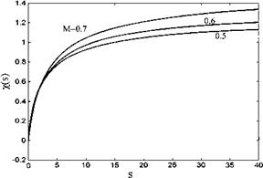
The values for the exponents of each function with respect to the Mach number are given in Table 5.1. Figure 5.8 gives the plots for the Kussner function in terms

of three different Mach numbers. The compressibility effect in these plots is evident as the steady state is reached.

Doublet-Lattice Method

The doublet lattice method is based on a linear theory using a numerical approach to study the subsonic three dimensional flows past complex lifting surfaces (Albano and Rodden 1969). In this method as lifting surfaces, the wing, the horizontal and vertical tails are subdivided into trapezoidal surfaces (the parallel sides of the trapezoids are in line with the free stream direction) to discretize the flow domain. In addition, if there is a tank or a store as an external type body, its surface is also subdivided into trapezoids during discretization. In order to dis­cretize a surface on each panel, a doublet line is placed at quarter chord of the panel and a control point is assigned at three quarter chord point as shown in Fig. 5.6. On the doublet line the unknown but constant value of the doublet strength is considered and at the control point known downwash value is assigned. This way the Kutta condition is satisfied numerically. As seen in Fig. 5.6, the wing surface is divided into n panels where the information about locations of the doublet line and the control points are used to obtain the algebraic equations from Eq. 5.37 using numerical integration.

The downwash, wi, induced on the control point of the ith panel by the doublet lines of the panels j = 1, 2, 3,…,n, shown in Fig. 5.6, can be expressed as follows

n

w = jj (5-51)

j=i

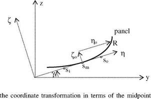
Here, Dij is written in terms of the numerical integrals over the Kernel function. In order to perform the numerical integrals for each penal we have to transform the local coordinates (П, g, f), into the global coordinates (x, y, z), as shown in Fig. 5.7.

image97

I

According to Fig. 5.7 tangent angle ys reads as

Подпись:image98"g = y cos ys + z sin ys 1 = —y sin ys + z cos ys

Using the geometry of the panel shown in Fig. 5.7, we can obtain the coefficient matrix Dij of Eq. 5.51 as follows. First we determine the coordinates of the control point, R = (xR, yR, zR), then the doublet line coordinates as inner left, si, middle: sm, outer right, so, coordinates are considered. If there is a spanwise curvature for the wing the local coordinates from the global ones read as

g0 = (yR — ySm) cos ys + (zr — ZSm) sin Js

10 = -(yR — ysm) sin ys + (zr — ZSm) COs ~fs

r = g 0 + l0

If the doublet line length is j and the angle between the doublet line and the span is kj then let us define e = 1/2 lj coskj. The value of the Kernel function in terms of new coordinates becomes

j = rK and Km = j(R, Sm), Ki = k(R, Si), K0 = k(R, S0).

Подпись: I Подпись: li Doublet-Lattice Method Подпись: (5.52)

If the panel length is small enough the parabolic change of the Kernel function will give us sufficiently accurate approximation. Accordingly, along the doublet line we have the following approximate integral to represent the Kernel integration with respect to di

Here, A, B and C respectively read as

A =(Ki — 2 Km + K0)/2e2, B =(K0 — Ki)=2e, C = Km

Doublet-Lattice Method Doublet-Lattice Method

The resulting

With all these, we have given the necessary information for the ‘doublet-lattice’ method to be applied numerically. This method is applicable to wing-tail, wing – external store and wing-fuselage interaction problems as well as the wings with curved spans.

Kernel Function Method for Subsonic Flows

The Kernel function method, known also as the pressure mode method, is used for solving the lifting pressure value via the integral equation, 5.37, for the prescribed motion of a thin wing in subsonic flows. The expression for the Kernel function was given in Eq. 5.36 as follows.

image91image92Oz2 Oz R

—1

Kernel Function Method for Subsonic Flows Kernel Function Method for Subsonic Flows Подпись: iMky + b _‘lyl e T Mb(ky)

Watkins et al. gives the open form of the kernel function in terms of the hypergeometric functions; K1: first order modified Bessel function of the second kind, If. first order modified Bessel function of first kind, and L1: first order modified Struve function as follows.

Подпись: M/b I y/l + s2e—ft|y'|TdT 0

Mkx +^J(kx’)2+b2(ky’)2 ф ukX+^J(kx )2+b2(ky’)2]

(Mky f J(kx )1+b’2(ky )2

(5.42)

Here, all the coordinates are nondimensionalized with root half chord, b0.

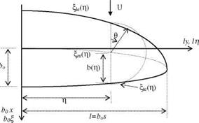
Подпись: Fig. 5.4 The planform and the variables for transformation
image94

In order to solve for the lifting pressure with the kernel function method we need to expand the lifting pressure in to the sin series similar to that given for Eq. 5.40. In doing so, we need to transform the chordwise coordinates for an arbitrarily shaped planform as shown in Fig. 5.4.

Подпись: Hm - COS в, b0 Подпись: 0 < в < p and Пт Подпись: He + Hie Подпись: b = He - Hie b0 2

As seen in Fig. 5.4, at any station along span, we use an angular coordinate в along the chord. The midchord variation along the span can be expressed in terms of the spanwise coordinate g. Using this approach we can deal with the planforms having not only straight but also curved edges. Now, we can write the chordwise H coordinate in terms of the angular в coordinate as shown in Fig. 5.4 as follows

The unknown lifting pressure in Eq. 5.37 can be expressed in terms of the transformed coordinates in a following manner.

Подпись: (5.43)Dp (в, g)= 4 ppU2 Ь(в, g) b0

Подпись: w (x, y) U Подпись: bpi 4ppU2 Подпись: 1 Hte(g) Dp(H, g)K(M, к, X, sy')dH dg 1 Hie(g) Подпись: (5.44)

Substituting 5.43 into 5.37 gives

Now, we can expand the nondimensional lifting pressure, Ь(в, g), into proper series (Ashley et al. 1965) as follows

Подпись:L(в, g)=-bv1 – g2

Подпись: (5.45)+ (яю + g Я11 + g2«12 + –•) sin в…

42 +22^(ял0 + g Яп1 + g яп2 + • — sin пв

Here, coefficients япт are the unknowns to be determined. Equation 5.45 can be written as the product of two entities as follows

ь(в, g)=у X inmn(g) (5.46)

п

In 5.46, for n = 0: 10(в) = cot |, and Іп(в) = ^ sin пв, n > 1,

An (g) = J 1 – g2 (Яп0 + gЯп1 Л———— h gm«nm Л—- ) = V1 – g2 X gm«nm

т

(5.47)

If there is a symmetric loading on the wing we take the even powered terms and for the antisymmetric loading the odd powered terms of series 5.47.

The integral equation 5.44 has a kernel with a strong singularity. In order to prevent the difficulties in numerical integration function K is rewritten as K with a scaling presented in a following manner

Подпись: (5.48)

Подпись: w (x, y) U Kernel Function Method for Subsonic Flows Подпись: (5.49)

K[M, k, x’, s(y – g) = bls2(y – g)2K[M, k, x’, s(y – g), s = l/bo The integral equation with the aid of 5.48 becomes

Here, in its open form K reads as

Подпись:M, k, X – Пт + Ъ cos в, s(y – g)

Подпись: w (x, y) U Kernel Function Method for Subsonic Flows Подпись: ln(h)Ke(M, k, в, g) sin вdh. Подпись: (5.50)
image95

The series expressions 5.46-5.47 for the nondimensional lifting pressure, L(h, g), can be substituted in integral equation, 5.49, to obtain the following system of linear equations written in double series

The right hand side of the Eq. 5.50 is given as the boundary condition. Unknown coefficients, anm, at the right hand side of the equation can be deter­mined with taking as many control points on the wing as unknowns. The lifting pressure values at these stations are then calculated using 5.46.

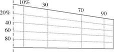
In Fig. 5.5, there are 20 (5 spanwise x 4 chordwise) unequally spaced control points, including the root chord, on a symmetric wing. There are some rules to follow while choosing the control points. These are:

(i) No control points are placed at the wing edges. Sufficient number of points, no less than 20, in chordwise and spanwise directions must be taken.

(ii) In symmetrical loadings even powers of m and antisymmetrical loadings odd powers of m must be considered.

(iii) For high reduced frequencies more number of control points must be taken.

(iv) If there are control surfaces on the wing the control points must be chose accordingly.

Hitherto, we have formulated the kernel function method applicable to subsonic flows over thin wings. In next section we are going to study a new method called

image96"Fig. 5.5 Representative con­trol points on the wing

‘Doublet-Lattice’ method applicable to general problems involving more complex wings with control surfaces and tails and tail wings.

Subsonic Flow Past an Airfoil

Before studying three dimensional subsonic flow, we are going to start our analysis with two dimensional flows. There are two options to do so. We either rederive the equations for two dimensional flows or we take the integral of the three dimen­sional acceleration potential in y to make the equations independent of spanwise direction. Here, the latter approach is preferred since we have already obtained the necessary expression to be integrated only. Integrating 5.36 from —1 to 1in spanwise direction we obtain

Subsonic Flow Past an Airfoil Подпись: mM Ub2
Подпись: W2D image90
Подпись: W3Ddg
Подпись: (x
Подпись: —1

(5.38)

Let us now write the amplitude of the downwash in terms the lifting pressure using the Kernel function for two dimensional flows (Bisplinghoff et al. 1996).

b

w(x) =———– 2 Ap(-)K M, – d-, —b < x < b (5.39-a)

Pi u2 b

—b

Subsonic Flow Past an Airfoil Подпись: (5.39-b)

Here, if we take k = kx—- and u = k^j—-, the kernel function K, in terms of Mach number and the reduced frequency reads as

Equation 5.39-a is called the Possio integral equation. Possio tried to solve his equation in terms of the Fourier series, however, his solution technique confronted with the convergence problem. A different approach from Possio to remedy the convergence problem is to employ Fourier like series for the lifting pressure expressed in – = b cosh coordinates. A new way of approximating the pressure discontinuity is

1

Ap(9)= A0 cot – + An——— , 0 < в < n (5.40)

2 n

n=1

Subsonic Flow Past an Airfoil Подпись: i = 0,..., N Подпись: (5.41)

The cotangent term in 5.40 gives an integrable singularity for the lifting pressure at the leading edge while satisfying the Kutta condition with zero lifting pressure at the trailing edge. The integral of the second term of Kernel function, 5.39-b, can be evaluated numerically. In doing so, keeping the number of control points on the chord equal to the number of terms in Eq. 5.40 enables us to have a number of algebraic equations equal to the number unknowns with complex ele­ments. The right hand sides of the equation, fi, are the known values of the prescribed airfoil motion to result in following set of linear equations.

Here, x = b cos u denotes the coordinates for the control points.