Our heavyweight helicopter equal in the world does not have
In Rostov started production of the most load-lifting rotary-wing car The Russian holding «Helicopt[...]

Everything about aircrafts and helicopters. News and events in aviation worldwide. Civil, transportation, military helicopters and airplanes.

Everything about aircrafts and helicopters. News and events in aviation worldwide. Civil, transportation, military helicopters and airplanes.

Everything about aircrafts and helicopters. News and events in aviation worldwide. Civil, transportation, military helicopters and airplanes.

Everything about aircrafts and helicopters. News and events in aviation worldwide. Civil, transportation, military helicopters and airplanes.


The subject of flight dynamics is characterized by an interplay between theory and experiment. This Tour has attempted to highlight this interplay in a number of ways. Marking the four reference points early on the Tour – the environment, the vehicle, the task and the pilot – an attempt has been made to reveal the considerable scope of the subject and the skills required of the flight dynamics engineer. The importance of strong analytical tools, fundamental to the understanding of the behaviour of the helicopter’s interacting subsystems, was emphasized in the modelling section. The powerful effect of aerodynamics on the flapping rotor was examined in some detail, with the resonant response highlighted as perhaps the single most important characteristic of rotor dynamics, enabling easy control of the rotor disc tilt. The modelling of flight dynamics was discussed within the framework of the frequency and amplitude of motion with three fundamental problems – trim, stability and response. The second major topic on the landscape of this Tour was flying quality, characterized by three key properties. Flying qualities are pilot-centred attributes; they are mission – and even task oriented, and they are ultimately the synergy between the internal attributes of the aircraft and the external environment in which it operates. Flying qualities are safety attributes but good flying qualities also allow the performance of the helicopter to be fully exploited. The remaining chapters of this book cover modelling and flying qualities in detail.
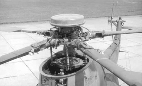
The instrumented rotorhead of the DRA (RAE) research Puma
(Photograph courtesy of DRA Bedford)
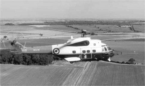
The DRA (RAE) research Puma in trimmed flight over the
Bedfordshire countryside (Photograph courtesy of DRA Bedford)
|
Fig. 2.51 Simple feedback augmenting pitch rate damping |
SCAS and integrated displays go some way to providing this. Autostabilizers were first developed to increase the helicopter’s operational envelope to include flight under instrument conditions. The first priority was to provide artificial stability to ensure that the aircraft would not wander off when the pilot’s attention was divided with other tasks. If we consider the addition of rate damping in the pitch axis, we can write the feedback law in proportional form:
Oisa = kqq (2.84)
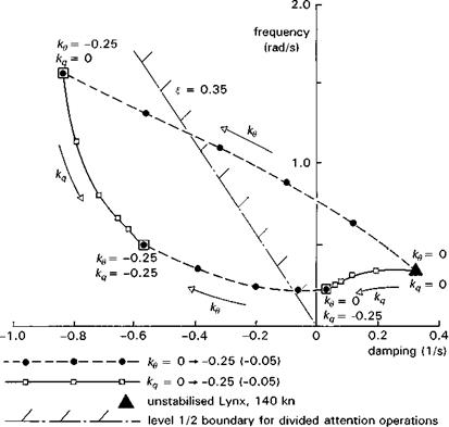
Figure 2.51 shows a block diagram of this feedback loop. With this proportional feedback working, as the helicopter flies through turbulence, every 1°/s of pitch rate change is counteracted by k° of longitudinal cyclic pitch Ois. The higher the value of gain kq, the greater the ‘artificial’ stability conferred on the helicopter. The root loci in Fig. 2.52 illustrates how the high-speed unstable pitch mode can be stabilized through pitch rate feedback for Helisim Lynx. We can see that even with quite high values of gain magnitudes (~ 0.25), the aircraft is still marginally unstable. Gain magnitudes much higher than about 0.2 would not be acceptable because the limited authority of today’s SCAS designs (typically about ±10% of actuator range) would result in the augmentation quickly saturating in manoeuvres or moderate turbulence. We can conclude from this discussion that rate feedback is insufficient to provide the levels of stability required for meeting Level 1 flying qualities in divided-attention operations. If we include attitude stabilization in the feedback loop, the control law can be written in proportional plus integral form
Oisa = kqq + ko J q dt (2.85)
Attitude feedback provides an effective stiffness in the pitch axis, and increasing ko serves to increase the frequency of the unstable pitch mode as shown in Fig 2.52. An appropriate combination of rate and attitude feedback can now be found to ensure Level 1 flying qualities and most modern SCAS designs incorporate both components. Rate and attitude feedbacks provide stability augmentation; but do nothing positive for control augmentation; in fact, the control response is reduced as the stability augmentation fights the pilot’s actions as well as disturbances. Control augmentation is
|
Fig. 2.52 Variation of long period pitch mode frequency and damping with autostabilizer gains for Lynx at 140 knots |
accomplished by feeding forward the pilot’s control signals into the SCAS, applying shaping functions or effectively disabling elements of the stability augmentation during manoeuvres. Different SCAS designs accomplish this in different ways; the Lynx system augments the initial response with a feedforward signal from the pilot’s control, while the Puma system disables the attitude stabilization whenever the pilot moves the controls. More modern systems accomplish the same task with greater sophistication, but modern SCAS designs that interface with mechanical control systems will always be limited in their potential by the authority constraints designed to protect against failures. In the limit, increasing the authority of the augmentation system takes us towards ACT where the pilot’s control (inceptor) inputs are combined with multiple sensor data in a digital computer to provide tailored response characteristics. ACT is still a developing technology for rotorcraft at the time of writing, but the potential benefits to both military performance and civil safety are considerable and can be classed under three general headings:
(1) task-tailored Level 1 flying qualities throughout the OFE, e. g., tailored for shipboard recoveries, underslung load positioning or air combat;
(2) carefree handling, ensuring safe operations at the edges of the OFE;
(3) integration with mission functions, e. g., navigation, HUMS.
The introduction of ACT into helicopters also offers the designer the opportunity to explore control-configured designs, in much the same way that fixed-wing military aircraft have developed over the last two decades. Even with the conventional single-rotor helicopter, ACT can free the designer to remove the empennage stabilizers altogether or alternatively to make them moving and under computer control. The main rotor could be made smaller or lighter if a carefree handling system were able to ensure a particular loading pattern in manoeuvres and at the OFE boundary. Of course it is with the more advanced rotorcraft concepts, with multiple control motivators, e. g., tilt rotors and thrust/lift compounding, that ACT will offer the greatest design freedoms and flying qualities enhancement. While this book has little to say about the flight dynamics of advanced rotorcraft, the author is conscious that the greatest strides in the future will be made with such configurations, if the ‘market’ can afford them or if the military requirements are strong enough.
The main rotor is the motivator for all but yaw control on the conventional helicopter, and before the fuselage can respond, the rotor must respond. The faster the rotorspeed, the faster the rotor flap response to control application and hence the faster the fuselage response. In many respects, the rotor acts like an actuator in the control circuit but there is one important difference. The rotor DoFs, the flap, lag and torsional motions, are considerably more complex than a simple servo system and can have low enough damping to threaten stability for high gain control tasks. Such potential problems are usually cured in the design of the SCAS, but often at the expense of introducing even further lags into the control loops. With typical actuator and rotor time constants, the overall effective time delay between pilot control input and rotor control demand can be greater than 100 ms. Such a delay can halve the response bandwidth capability of an ‘instantaneous’ rotor.
The five issues discussed above are compoundedby the special problem associated with manoeuvring close to the ground and surrounding relief – providing an adequate field of view (FoV); the issue was expressed succinctly by Prouty (Ref. 2.45):
The most important flying cue a pilot can have is a good view of the ground and
everything around.
Field of view is a significant design compromise, most helicopters suffering from an inadequate FoV from a flying qualities perspective. Overhead panels in side-by-side cockpits obscure the view into turns and tandem seaters can be deficient in forward and downward views.
Fixing flying qualities deficiencies during flight test development can be very expensive and emphasizes the importance of accurate simulation, model testing and analytical tools in the design process. It also emphasizes the critical importance of validated design criteria – what constitutes good flying qualities for helicopters – and this book addresses this question directly in Chapter 6.
Artificial stability
It should be clear to the reader from the various discussions on this Tour that it is difficult to design and build helicopters that naturally exhibit Level 1 flying qualities. Pilots need help to fly and perform missions effectively in helicopters, and modern
The instabilities of the helicopter fall into two categories – those at low speed due to the rotor and those at high speed due to the rotor; the designer can do very little about the first with airframe design, but he can make flight at high speed almost as stable as a fixed-wing aircraft. Unfortunately, if he chooses the latter option, he will almost certainly compromise control and agility. Building large enough fixed empennage stabilizers will always work but will, in turn, increase the demands on the rotor for manoeuvres. Selecting a rotor with zero or low equivalent hinge offset (e. g., most articulated rotors) will probably result in the pitch axis being marginally stable in high speed, but will again reduce the agility of the aircraft. On the other hand, a hingeless rotor, providing a roll time constant equivalent to a fixed-wing aircraft (0(0.1 s)) will also result in an unstable pitch mode with time to double of less than 1 s at high speed.
At low speed, without mechanical feedback, the single rotor helicopter is naturally unstable. The coupled pitch/roll, so-called pendulum instability is a product of the flapping rotor’s response to velocity perturbations. The mode is actually a fairly docile one, and is easily controlled once the required strategy is learnt, but requires considerable attention by the pilot. However, if the outside world visual cues degrade, so that the pilot has difficulty perceiving attitude and velocity relative to the ground, then the hover task becomes increasingly difficult and Level 3 qualities are soon experienced.
The boundary of the operational flight envelope should not be characterized by loss of control or performance; there should always be a safe control and performance margin for operation at the OFE limit. Most of these limit boundaries are not signposted however, and inadvertent excursions into the region between the OFE and the SFE boundary can and do happen, particularly when the crew’s attention is diverted to other matters. Helicopters with low power margins can get caught in large-scale downdrafts behind buildings and other obstacles or terrain culture, making it very difficult for a pilot to arrest a rate of descent. Turning downwind can cause a helicopter to fly close to the vortex-ring region if the pilot judges his speed relative to the ground rather than the air. Both these examples can lead to a sharp reduction in lift and height and represent conditions most like wing stall for a fixed-wing aircraft. Hovering or manoeuvring at low speed close to obstacles in strong winds can also lead to loss of tail rotor control authority, or even, in exceptional cases, to a loss of cyclic control margins. Being ‘out-of – (moment) control’ close to obstacles can be as dangerous as losing lift. At high speed, or while manoeuvring in the mid-speed range, the rotor can experience local blade stall. While this is unlikely to have much effect on the overall lift, if the retreating blade stalls first, the aircraft will experience a nose-up pitching moment, further exacerbating the stall. Forward motion on the cyclic to correct the motion applies a further pitch increase on the retreating side of the disc, worsening the stall. There are very little data available on the handling qualities effects when the rotor is partially stalled in high-speed flight, but clearly flying qualities will degrade. Once again, the designer is forced to make a compromise. A low disc loading, highly twisted rotor serves hover and low-speed performance and handling, while a high disc loading, untwisted rotor gives better manoeuvrability and ride at high speed. From the designer’s perspective, the alternate yaw control devices like the fenestron and Notar (Refs 2.5, 2.6) are attractive options to the open tail rotor if vulnerability is a major concern, even though handling and performance may be compromised.
Perhaps the greatest distinguishing feature of helicopters, and a bane in the designer’s life, cross-couplings come in all shapes and sizes. On hingeless rotor helicopters in hover, the off-axis roll response from a pitch input can be as large as the on-axis response. At high-speed, the pitch response from collective can be as strong as from longitudinal cyclic. The yaw response from collective, due to the torque reaction, can require an equivalent tail rotor collective input to compensate. At high speed the pitch response from yaw can lead to dissimilar control strategies being required in right and left turns. These high levels of impurity again stem principally from the main rotor and its powerful wake and are inherent features of helicopters. During the 1970s and 1980s, several new designs underwent extensive flight test development to minimize the flying qualities deficiencies caused by cross-couplings and response impurities. The residual forces and moments and associated aircraft accelerations induced by these couplings can lead to serious shortcomings if high performance is being sought. For example, the saga of the empennage development for the AH64 (Ref. 2.43) and the AS 360 series helicopters (Ref. 2.44) indicate, on the one hand, how extensive the redesign to fix handling qualities can be, and, on the other, how much improvement can be obtained by careful attention to detail, e. g., in the aerodynamic characteristics of the horizontal and vertical stabilizers.
The helicopter rotor is sensitive to velocity perturbations in all directions and there is very little the rotor designer can do about this that doesn’t compromise control response. Early attempts to build in natural dynamic couplings that neutralized the rotor from external disturbances (Refs 2.40, 2.41) resulted in complex rotor mechanisms that only partially succeeded in performing well, but, for better or worse, were never pursued to fruition and production. In reality, such endeavours were soon overtaken by the advances in ‘electronic’ stabilization. All motion axes of a helicopter have natural damping that resists the motion, providing a basic rate command control response in the very short term. However, soon after a control input is applied, the changes in incidence and sideslip give rise to velocity variations that alter the natural rate response characteristics in all axes. This can occur within a very short time (0(1 s)) as for the pitch axis response in high-speed flight, or longer (O(several seconds)) as for the yaw response in hover. The impurities require the pilot to stay in the loop to apply compensatory control inputs, as any manoeuvre develops. Apart from the main rotor sensitivity, the tail rotor and empennage sensitivities to main rotor wake effects can also introduce strong impurities into the control response. The size, location and incidence of the horizontal stabilizer can have a profound effect on the pilot’s ability to establish trims in low-speed flight. Likewise, the tail rotor position, direction of rotation and proximity to the vertical stabilizer can significantly affect the pilot’s ability to maintain heading in low-speed flight (Ref. 2.42). Both horizontal and vertical tail surfaces are practically redundant in hover and low-speed flight but provide natural stiffness and damping in high-speed flight to compensate for the unstable rotor and fuselage. The modelling of the interactional flowfields is clearly important for predicting response impurities and will be discussed further in Chapter 3.
In the helicopter design trade-off, flying qualities have often had to take a low priority. In the early days of rotorcraft, just as with fixed-wing aircraft, solving the basic control problem was the breakthrough required for the development to progress with pace, driven largely by performance considerations. The basic layout of the single rotor helicopter has remained the same since the early Sikorsky machines. What characterizes a modern helicopter is its higher performance (speed, payload), much improved reliability – hence greater safety, smoother ride and a suite of mission avionic systems that enable civil operations in poorer weather and military operations as an autonomous weapon system. Performance, reliability, comfort and functionality have been the drivers in helicopter development, and for many years flying quality was a by-product of the design, with deficiencies compensated for by highly trained pilots with a can-do attitude. As we have seen from our discussions earlier on this tour, helicopter flying characteristics are typically much poorer than fixed-wing aircraft in the same ‘class’. In some cases, helicopters fall in the Level 3 quality area when built. The principal flying qualities deficiencies in the helicopter can be summarized as follows:
(1) impurity of the primary response in all axes, i. e., typically a mix of attitude or rate and varying significantly from hover to high speed;
(2) strong cross-couplings in all axes;
(3) the degradation of response quality at flight envelope limits and the lack of any natural carefree handling functions, e. g., the aerodynamic capability of the rotor typically exceeds the structural capability;
(4) the stability of a helicopter is characterized by a number of modes with low damping and frequency at low speed; as forward speed is increased, both longitudinal and lateral modes increase in frequency, as the tail surfaces contribute aerodynamic stiffness, but the modal damping can reduce and stability can often worsen, particularly with highly responsive hingeless rotors;
(5) the rotor presents a significant filter to high bandwidth control.
The combination of the above has always demanded great skill from helicopter pilots and coupled with today’s requirements for extended operations in poor weather and visibility, and the need to relieve the piloting task in threat-intensive operations, led to the essential requirement for stability and control augmentation. Before discussing artificial stability, one first needs to look more closely at the key natural design features that contribute to flying qualities. The discussion will map directly onto the five headings in the above list and an attempt is made to illustrate how, even within the flying qualities discipline, compromises need to be made usually to satisfy both high – and low-speed requirements simultaneously.
A key emphasis on this stage of the Tour has been to highlight the importance of the relationship between flying qualities and the task or mission. Outside the context of a role and related tasks, the meaning of quality becomes vague and academic. Flying or handling qualities are not just stability and response properties of the air vehicle, but the synergy between what we have called the internal attributes of the aircraft and external influences. Flying qualities can be assessed objectively through analysis and clinical measurements, and subjectively through pilot opinion of the ability to fly MTEs within defined performance and workload constraints. The 1980s and 1990s saw considerable development in helicopter flying qualities, relevant to both design criteria and compliance demonstration, and Chapters 6 and 7 will present and discuss many of the new concepts in depth. There still exist gaps in the knowledge base however, largely due to an inadequate flight test database, and these areas will be highlighted. One of the important underdeveloped areas relates to the requirement for upper flying qualities limits. These are important for military roles requiring agility, where the assumption that more performance is always better is strongly countered by experience with oversensitive control response and unusable control powers. Agility will be covered in the
section on special flying qualities in Chapter 7. The quantification of handling qualities degradation due to a variety of internal and external effects also represents a significant gap, and in Chapter 8 we discuss a number of the more significant issues.
It is recognized that without some form of stability and control augmentation system (SCAS), helicopters stand little chance of achieving Level 1 flying qualities for anything but the simplest of tasks. However, we need to be interested in the so-called bare-airframe flight dynamics for several reasons. First, the unaugmented characteristics form the baseline for SCAS design; the better they are known, the more likely that the SCAS design will work properly first time. Second, the case of failed augmentation systems has to be considered; the level of bare-airframe characteristics determine whether the SCAS is flight-safety or mission critical, i. e., whether the mission or even safe flight can be continued. Third, the better the flying qualities conferred by bare – airframe design, the less authority the SCAS requires, or the lower the gains in the feedback loops, and hence the more robust will the aircraft be to SCAS failures. And fourth, with a limited authority SCAS, any saturation in manoeuvring flight will expose the pilot to the bare-airframe characteristics; any problems associated with these conditions need to be well understood.
Clearly, SCAS performance is closely linked with the flight dynamics of the bare airframe and they both together form one of the drivers in the overall helicopter design, a subject that we now briefly visit on the last stop of this Tour.
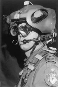
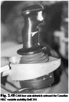
This tour of flying qualities would not be complete without some discussion on the other key characteristics associated with the air vehicle that have a primary effect on flight path control – the pilot’s inceptors and displays. To dispel any myths that these are secondary issues it must be said that poor characteristics in either of these two areas can ruin otherwise excellent flying qualities. Of course, pilots can and will compensate for poor mechanical characteristics in cockpit controls, but the tactile and visual cues provided through these elements are essential for many flight phases. Sidestick controls and helmet-mounted displays are components of ACT and are likely to feature large in the cockpits of future helicopters (Figs 2.48, 2.49). Examples of recent research with these devices will be outlined in Chapter 7.
Operational benefits of flying qualities
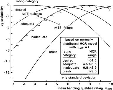
So, what are the operational benefits of good flying qualities? Are they really significant or merely ‘nice to have’? We have seen that one of the potential consequences of flying qualities deficiencies is loss of control, leading to structural damage, pilot disorientation and a crash. We have also seen that an aircraft that exhibits Level 1 characteristics in one situation can be Level 2 or even 3 in degraded or more demanding conditions. A question then arises as to the likelihood of a aircraft running into these situations in practice. This topic has recently received attention in the fixed-wing civil transport community in an attempt to quantify the probability of human error leading to a crash (Ref. 2.38). The same approach was taken to quantify the benefits of having baseline Level 1, as opposed to Level 2, flying qualities for military rotorcraft (Ref. 2.39). This research, which will be described in more detail in Chapter 7, derived a result that is summarized in Fig. 2.50. This shows the probability of achieving MTE success,
|
Fig. 2.49 GEC biocular helmet-mounted display |
|
Fig. 2.50 Probability of rating category as a function of HQR |
failure or loss of control (leading to a crash) as a function of mean HQR (derived, for example, from an ADS-33 objective assessment). The results are somewhat intuitive and fall out from fairly simple statistical analysis. There are a number of assumptions that need careful examination before the kind of results depicted in Fig. 2.50 can be substantiated, however, and these will be pursued further in Chapter 7. The approach, while somewhat controversial, has considerable appeal and opens up opportunities for providing a direct effectiveness measure for flying qualities.