Category HELICOPTER FLIGHT DYNAMICS

Recapping the usable cue environment

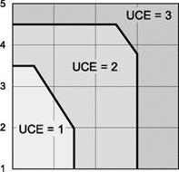
Just like the sparrow hawk, a pilot flying a helicopter close to the surface and near obsta­cles requires clear visual information for attitude stabilization and flight path guidance, tasks not too dissimilar to cycling or walking over uneven or rough terrain. Although critical for short-term stabilization, vestibular motion cues are generally unreliable for guidance; turn the lights off or shut the eyes, and the cyclist or walker would soon fall over. Attitude stabilization cues for helicopter flight are derived from knowledge of the horizon, an awareness of spatial orientation and rotational motion. The requirements of ADS-33 are quite clear about the importance of stability augmentation when the usable cue environment (UCE) degrades below 1. Figure 8.1 summarizes the material presented in Chapter 7 – increased attitude stabilization (attitude command) as the

Visual cue rating


1 – p Good

2 —

3 — Fair

4 —

5 – L – Poor Attitude


1 – p Good

2 —

3 — Fair

4 —

5-L – Poor Translational rate


Ranking defined in ADS 33


UCE

Respose types in hover/low speed flight

UCE 3

TRC + RCDH + RCHH + PH

UCE 2

ACAH + RCDH + RCHH + PH

UCE 1

RC

Response types

RC – rate command

TC – turn coordination (applies to yaw and pitch response) ACAH – attitude command, attitude hold (roll and pitch)

RCDH – rate command, direction hold (yaw)

RCHH – rate command, height hold (heave)

PH – position hold (horizontal plane)

TRC – translational rate command


О


Useable Cue Environment (UCE)


Подпись: Degraded Flying Qualities 521

со

с

л


1 2 3 4 5

Attitude VCR


UCE degrades to 2 and increased velocity stabilization (translational rate command) as the UCE degrades to 3.

In Ref. 8.10, Hoh applied the UCE/VCR approach to quantifying the risk of spatial disorientation when flying in the DVE, using the original ADS-33 flight test database. The work reported addresses the wide class of ground/obstacle collisions that occur when aircrew are unaware that they have an inaccurate perception of their position, altitude or their motion. Hoh’s analysis models situations where the overall pilot workload is a combination of the attentional demands (AD) of flight control and the effort required to maintain situation awareness (SA). The greater the requirements for control attention, the less capacity remains for SA and Hoh hypothesizes a relationship. To quote from Ref. 8.10

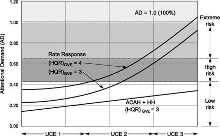
The risk of a spatial disorientation accident is linked to the attentional demand requiredfor control as follows. High risk is defined when attentional demand exceeds 42% of the total available workload capacity. Extreme risk is defined when the AD exceeds 66% of the available workload capacity. The attentional demand for rotorcraft control in the DVE depends on two factors, 1) the basic handling qualities in the GVE and 2) the Response Type (Rate orACAH + HH). The relationship between these factors is summarised in Fig. 8 where the attitude VCR and translational VCR are assumed to be equal to simplify the presentation of the effects. These results indicate that as the visual environment is degraded: 1) the use ofACAH+HH is highly effective in minimising the increase in AD, and 2) helicopters with a rate response type (conventional) suffer a rapid increase in AD. Any factor that degrades the HQR in the GVE (e. g. marginal basic handling qualities or turbulence) exacerbates the second result.

The presentation in Fig. 8.2 is compelling but also conceptual, since it is acknowledged that the relationships between handling qualities, control workload and UCE proposed

Fig. 8.2 Summary of the effect of the DVE on attentional demand (from Ref. 8.10)

are approximate and have not been fully quantified or validated. Nevertheless, they represent an intuitive and compelling argument for the importance of providing the pilot with augmented attitude control in the DVE. Moreover, Hoh concludes that providing additional instruments or displayed information to ‘cue’ the pilot can actually increase, rather than decrease, the AD, further increasing the risk of disorientation.

With this line of thinking, research into improving the UCE becomes focused on improving spatial awareness for the pilot. This research needs to establish relationships between the pilot’s VCRs, features in the visual scene and the pilot’s control strategy. The two components of a pilot’s VCR can be thought of the adequacy of cues for flight guidance (translational rate) on the one hand, and the adequacy of cues for flight stabilization (attitude) on the other, i. e., the two dimensions of spatial awareness. While the previous discussions in this book on flying qualities have centred on the vehicle and the associated response characteristics, when addressing spatial awareness, we have to face the most adaptable and least well-understood element of the system and, indeed, the whole flying qualities discipline – the pilot and his or her perception system. To understand more about what makes up the UCE/VCR, we need to develop an engineer’s appreciation of how the pilot organizes visual information and the human factors of flight control. Improved understanding here can lead to the development of more efficient pilot aids that function harmoniously with the natural systems, and are hence more effective at helping pilots maintain spatial awareness. Unlike the aircraft motion however, pilot action is not simply governed by Newton’s laws and the rules of continuum mechanics; the perception-action system is far from completely understood and behaviour is often confused by misjudgements and malfunctions that are difficult to describe, let alone model. The following sections should be read in the light of this uncertainty.

Flight in Degraded Visual Environments

Imagine a bird flying through a cluttered environment; a sparrow hawk is a good example. It is so successful at avoiding bumping into things and eventually catching prey on the wing that we can assume that the bird has very accurate knowledge of

where it is heading, its rates of closure with objects in its path, its orientation and, more generally, its flight trajectory. How does it pick up the required information from the ‘visual flow’ of the world around it, projected onto its visual sensors? We might ask the same question of a fell-runner who successfully tracks over rough terrain without stumbling, or indeed an athlete who somersaults and lands, precisely balanced, on two feet, or a pigeon landing gently on the ledge rather than overshooting and crashing into the window. Motion control is ubiquitous in the natural world, and without completely reliable and precise functioning life would be very vulnerable. When the visual world is obscured, so too are the stimuli to the perception system and again life becomes vulnerable; most life sleeps at night, with the visual sensors, the eyes, shut, although there are some notable exceptions, of course. However, in the world of man-made flying machines, we regularly practice flight at night and in poor visual conditions, and technology even allows us to land fixed-wing aircraft on narrow runways, or bring a helicopter to hover, in zero visibility. Without precise control augmentation however, such manoeuvres would not be possible and such precision approaches are only really possible in tightly controlled airspace. Inadvertent flight into a degraded visual environment (DVE) is extremely hazardous with a high risk of loss of control through a loss of awareness of spatial orientation. Looking to the future, technology is under development that will provide pilots with a sufficiently reliable ‘synthetic’ world in which they have confidence to manoeuvre, to exercise motion control, in a cluttered environment with no natural outside world information. Until then, flight will be risky in poor visibility. We can gain valuable information on motion control by studying flight in good visual environments (GVE). By doing this we can also attempt to build an engineering framework for motion control using visual stimuli, which can inform the development of vision augmentation systems. This is the theme of this section. Through his research into motion control in the natural world, this author has observed that the subject is still in development with different ‘schools of thought’ existing on the key stimuli and mechanisms involved. I have had to be selective in attempting to build the bridge between the engineering and psycho-physics approaches to flight control, and my foundation has, naturally, been the work of James Gibson and the developments of his theory of optical flow. In the quest for solutions to how to design for completely autonomous flight in a cluttered, undulating environment however, I believe strongly that there is much still to be learned and understood, and that much of the contemporary, seemingly contradictory, research will have helped to inform progress.

Flying qualities: forms of degradation

Подпись:The future of the helicopter is immense and later the craft will be a very familiar sight in the air to everyone. It will also be capable of rendering a great number of services which no other craft can render, and can be described as the greatest friend in need in the case of an emergency.

Igor Sikorsky at the end of his lecture ‘Sikorsky Helicopter Develop­ment’ presented to the Helicopter Association of Great Britain at Mansion House, London, on Saturday 8 September 1947

8.1 Introduction and Scope

As Sikorsky foretold with confidence and optimism 60 years ago in Ref. 8.1, the helicopter would indeed serve mankind as a ‘friend in need’, but as often happens, its unique capability would be usable only by pilots exercising very high levels of flying skills, and, in dangerous and emergency situations, by pushing both safety and performance to the limits. Sikorsky talked in his lecture about the significance of the helicopter in rescue service. He recounted a recent occurrence with ‘satisfaction and great encouragement’, to quote:

The police rang up the factory to say that an oil carrying barge with two men onboard was in distress and was starting to disintegrate, water sweeping over the surface of the barge. We immediately dispatched a helicopter with a hoisting sling and in spite of a wind of 60 m. p.h and gusty, the helicopter quickly reached the barge and was able to hover 20-25 ft. over it, lower the hoisting sling and take the men off, one after another. The rescue was made as the end of the day was approaching and the general consensus of opinion was that these two would certainly not have been able to stay on the damaged barge overnight.

Igor Sikorsky presented the lecture published as Ref. 8.1 just a few years after the birth of the practical helicopter. He talked about ‘. . . absolute accuracy of the control’ and ‘… control as perfect as any other system of control.’ Today, we can only try to imagine the motivation, the courage and the optimism of the early pioneers as they shaped the first vertical flight machines with four axes of control. A few months later, on 19 April 1948, as reported in Ref. 8.2 and discussed in the Introductory Tour to this book (Chapter 2), a Sikorsky S-51 during a test flight at the Royal Aircraft Establishment would almost crash as the pilot momentarily lost control during a high-speed (4 g) pull­out and inadvertent rapid roll to 90° of bank. The other side of the coin, so to speak, was experienced with the consequences of degraded handling qualities. Helicopter control, while qualitatively precise, would always require close pilot attentiveness and relatively high workload.

Chapter 7 ended with a discussion on the impact of flying qualities on safety and mission effectiveness. The twin goals of safety and performance, with the consequent tension between them, have pervaded the whole business of aviation since the Wright brothers’ first flight in December 1903. In the helicopter world, the performance-safety tension is perhaps strongest when flying close to the surface with what is sometimes described as mission imperative, or at the edges of the operational envelope, in harsh environments, or when the pilot has to deal with flight system failures. When flying close to the surface, the first priority for the pilot is to maintain a sufficient margin of ‘spatial awareness’ to guarantee safe flight. This spatial awareness also has a temporal dimension; the pilot is actually trying to predict and control the future flight trajectory. We can imagine a pilot flying to maintain a safe time margin, avoiding obstacles and the ground, with a relaxed control strategy allowing plenty of time for navigation and monitoring aircraft systems. The pilot will want to maintain a sufficiently long ‘time to encounter’ between the aircraft and any potential hazard, so that there is ample time to manoeuvre around, climb over or even stop, if required. But external pressures can make things more difficult for the pilot, increasing the workload. Imagine that the task is to transit, within tight time constraints, to deliver an underslung load to a confined forest clearing at night, with the threat of enemy action. Under relentless time pressures, the pilot has some scope for trading off performance and workload, depending on the requirements of the moment. He or she will be forced to fly low to avoid detection by the enemy. Increasing the tempo at low level reduces the safety margin; more precision or more agility requires higher levels of concentration on flight path guidance and attitude stabilization. The more the pilot concentrates on flight management, the more the global situation awareness is compromised with increased risk of getting lost or becoming disconnected with the military situation. Flying qualities affect and are powerfully affected by these demands and nowadays can be sensibly discussed only in terms of mission-oriented requirements and criteria, hence the considerable emphasis on the development of handling qualities engineering and the standards, particularly Aeronautical Design Standard-33 (Ref. 8.3).

Military standards have wholly embraced the concept of handling qualities levels and pilot assessment through the Cooper-Harper handling qualities rating scale, dis­cussed extensively in Chapter 7 of this book. For an aircraft to be fit for service (i. e., according to ADS-33 ‘… no limitations on flight safety or on the capability to perform intended missions will result from deficiencies in flying qualities’), it has to exhibit Level 1 handling qualities throughout the normal operational flight envelope (OFE). Degradation to Level 2 is ‘acceptable’ following the failure of some flight functions, in emergency situations or when the aircraft strays outside the OFE. Some operators may also allow Level 2 handling qualities in parts of the OFE, provided exposure is limited, e. g., deck landings in high sea states. Even though guided and constrained by their own experience and standard operational procedures, pilots need to make judgements all the time as to whether a particular manoeuvre is achievable or not. Sometimes they make the wrong judgement but the usual outcome is that the pilot gets a second chance at the landing or to position the load or pick up the survivor. Failing a mission task element (MTE) might push the aircraft into Level 3, but provided the degradation is not too severe the situation is recoverable. A more sudden or rapid degradation can push the aircraft towards the Level 4 condition however, where there is a high risk of loss of control. Chapter 7 closed with a statistical interpretation of the consequences on flight safety of an aircraft exhibiting different handling qualities (see Fig. 7.45). Acknowl­edging the assumptions of the analysis adopted, we drew the tentative conclusion that for an aircraft exhibiting a mean HQR at the Level 1/2 borderline, the probability of loss of control would be approximately 1 in 109 MTEs across the fleet. In comparison, an aircraft that exhibited a mean HQR in the middle of the Level 2 range would have a probability of loss of control across the fleet of about 1 in 105 MTEs, a massive increase in risk to safety.

These conclusions are borne out by the accident data. For example, in Ref. 8.4, Key pointed out that 54% of all accidents on the H-60 Blackhawk in the 10-year period up to 1996 involved deficiencies in handling qualities or situation awareness. The data also revealed that marginal handling was much more of a problem for low-time pilots. In a complementary study on US civil helicopter accidents, Ref. 8.5 reports that of the 547 accidents that occurred between 1993 and 2004, 23% could be ‘… attributed to loss of control by the pilot – caused or aggravated by inadequate or deficient handling qualities’. The relationship between handling and safety is an important link to make, even more so because in the drive to ‘weather-proof’ flight operations future rotorcraft will be required to perform roles in more degraded conditions than is currently possible with safety, hence an understanding of the ways degradation can occur, and some of the consequences, can assist in forming the requirements for day-night, all-weather augmentation systems. This chapter addresses these issues and material is drawn from the author’s own research over the 10 years since the publication of the first edition of this book, e. g., Refs 8.6-8.9. During the second half of this period, the author relocated to The University of Liverpool, creating and building a research group focused on all aspects of Flight Science and Technology, and with a strong emphasis on flight safety. Central to the research at Liverpool is the Bibby Flight Simulator and, within this chapter, research results using this facility are presented liberally; the simulation facility is described in some detail in Appendix 8A.

To create a framework for the chapter, handling qualities degradation is described in four categories:

(a) degradation resulting from flight in degraded visual conditions;

(b) degradation resulting from flight system failures, both transient and steady state;

(c) degradation resulting from flight in severe atmospheric disturbances;

(d) degradation resulting from loss of control effectiveness.

Strictly speaking, category (d) should not occur, almost by definition, within the OFE and usually results from pilots inadvertently straying outside this, as a result of degra­dations in categories (a)-(c). Discussion on category (d) situations, for example, loss of heave control following entry into vortex ring, loss of tail rotor effectiveness in quartering flight or loss of pitch/roll control power in high-speed stall, will not be included.

The Contribution of Flying Qualities to Operational Effectiveness and the Safety of Flight

The two overriding considerations for both civil and military rotorcraft operations are to achieve good performance at low workload. Like stability and agility, these dual aims can often conflict. Typically, military operations are characterized by achieving performance goals as a priority, while civil operations are biased towards safety. In any mission or operational situation, the pilot will make the tactical decision of which to favour but the tension between performance and safety is ever present. In consider­ing the contribution of flying qualities to effectiveness and safety, this tension forms a centrepoint of the discussion. The HQR scale measures pilot workload required to achieve a defined performance, hence giving an indication of the safety margins avail­able. HQRs are explicit measures of pilot workload and implicit measures of aircraft stability and control characteristics. However, there appears to have been very little work done on the operational benefits using the HQR approach. For example, how much more mission effective is a Level 1 than a Level 2 aircraft when, for example, the pilot is stressed due to poor weather or the need for rapid action? Generally, and in objective terms, the value of good flying qualities should be reflected in three principal areas:

(1) productivity – how many missions or sorties can be accomplished;

(2) performance – how well can each sortie be accomplished;

(3) attrition – how many losses can be expected.

We will examine these issues within the framework of a probabilistic approach along the lines first put forward in Refs 7.44 and 7.45 and later developed in Ref. 7.25. The basic notion is that flying qualities deficiencies increase the chance of pilot error, hence can lead to accidents, incidents or MTE failures. This is a controversial concept. A significant proportion of accidents and incidents are attributed to human error, but there is often a counter-argument put forward that suggests some deficiency in the aircraft’s handling qualities. In this context, Refs 7.44 and 7.45 considered the benefits to flight safety using the Cooper-Harper pilot rating scale as a metric (Fig. 7.2). These references considered the pilot as a vital system component who can fail (i. e., be stressed to failure) in an operational context, just like any mechanical or electrical component. Pilot failure can be manifested in MTE failure, corresponding to HQRs > 6.5 or, in the extreme, a loss of control, corresponding to a HQR > 9.5. We have already discussed on several occasions the variability of flying qualities with both internal attributes and external factors. In the life of an aircraft, there is a finite probability that ‘virtual’ ratings across the whole range will be experienced. We refer to these as virtual ratings because in reality they are not awarded; one can imagine, however, an HQR meter, sampling workload and pilot-set performance targets. For every distinguishable MTE that is flown, the HQR meter takes a recording. Examples might be as given in Table 7.6.

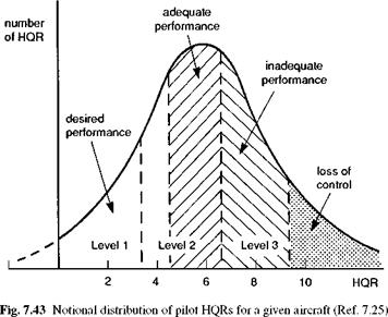
The next assumption we make is that over a long period of time the distribution of the virtual ratings takes a normal form as shown conceptually in Fig. 7.43. The regions of desired, adequate and inadequate performance are clearly identified. The desired and adequate regions can be considered as reflecting varying degrees of MTE success, while the inadequate level corresponds to MTE failure. Effectively, each mission is composed of a number of contiguous MTEs, each having its own virtual HQR. If a particular MTE

Table 7.6 Possible HQRs for same aircraft in different MTEs

Handling qualities rating

Mission task element

1

cruise on autopilot

3

landing in confined area in GVE

4

sidestep during NoE training flight

5

landing on ship in gusty conditions

6

landing in confined area in DVE

7

turn to acquire target, but target out of range

9

deliver underslung load in gusty DVE

10

crash following tail rotor failure

was assigned a Level 3 rating, then the pilot would have to either try again or give up on that particular MTE. Loss of control has obvious ramifications on mission success. For certain types of operation, loss of control will almost certainly result in a crash. The probability of obtaining a rating in one of the regions is proportional to the area under the distribution in that region. Note that, as discussed in Ref. 7.25, we include ratings greater than 10 and less than 1 in the analysis. The rationale is that there are especially bad and good aircraft or situations, whose qualities correspond to ratings like 13 or -2. However, the scale enforces recording them as 10 or 1.

Note too that the scatter produces, even with a good mean rating, a large probabil­ity of merely adequate performance and even a finite probability of total loss of control and, in some cases, a crash. We have said elsewhere in this book that flying qualities are determined by the synergy between internal attributes and external influences. It follows then that sources of scatter originate both internally and externally. Internals in­clude divided attention, stress and fatigue, pilot skill and experience. Externals include atmospheric disturbances, changing operational requirements and timelines, threats, etc. The flying qualities community has done much to minimize scatter by careful

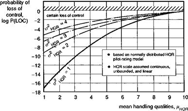
Fig. 7.44 Relationship between mean HQR and P(LOC) (Ref. 7.44)

attention to experimental protocol (Ref. 7.6), but here we emphasize that in opera­tional environments, the effective pilot rating scatter is omnipresent.

With the assumed normal distribution of ratings, the probability of control loss, Ploc, can be calculated for various mean ratings and dispersions; these are plotted in Fig. 7.44. Ploc is the probability of obtaining a rating greater or worse than 9.5, which in turn is simply proportional to the area under the distribution to the right of the 9.5 rating. Thus, the probability of loss of control (i. e., flight failure) due to flying qualities deficiencies can be estimated. For the cases studied in Refs 7.44 and 7.45 and depicted in Fig. 7.44, operating a Level 1 aircraft can be seen to reduce the probability of a loss of control by an order of magnitude relative to a Level 2 aircraft. Interestingly, the Ploc of an aircraft with a mean HQR of 3.5, on the Level 1/2 boundary, is 1 in 109, the value quoted for flight critical component reliability in civil transports.

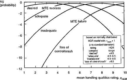
If we now consider the same approach applied to the full extent of the rating scale, the effectiveness in terms of MTE success or failure can be estimated. Figure 7.45 shows the probability of obtaining ratings in the various regions when the stan­dard deviation of the ratings is unity. This curve has some interesting characteristics. First, the intersections of the lines fall on the ratings 4.5, 6.5 and 9.5, as expected. Also it turns out that for a mean rating of 7, the probability of achieving inadequate performance is, of course, high, and we can also see that the probability of achieving desired performance is about the same as that for loss of control – about one in a hun­dred. Improving the mean HQR to 2 lowers the probability of loss to 10-13 (for our purposes zero) and ensures that performance is mostly at desired levels. Degrading the mean rating from 2 to 5 will increase the chances of mission failure by three orders of magnitude.

If we consider the above results applying to a fleet of 100 of the same aircraft type, some interesting statistics begin to emerge. We assume that each aircraft in the fleet flies one mission per day, and each mission comprises 20 MTEs. Over a 20-year period the fleet will fly about 15 x 106 MTEs. If we assume that loss of control equates to loss of an aircraft, then Fig. 7.45 provides information on the expected losses due to flying qualities deficiencies over the life of the fleet. For an aircraft with a mean

Fig. 7.45 Relationship between mean HQR and probability of mission success, failure and

loss of control (Ref. 7.25)

HQR of 5, the fleet can expect to lose one aircraft per year (i. e., 20% of the fleet over the fleet life). With a mean HQR of 3, no aircraft will be lost from poor handling qualities during the life of the fleet. It is likely that most operational aircraft in service today do not have mean HQRs in the Level 1 region, because of limited stability and control augmentation, the poor cueing of flight envelope limits and the degraded flying qualities associated with failures and in emergency situations. It would be inappropriate to discuss data on particular types in this book, but these preliminary results give some cause for concern; on the other hand, they also offer a methodology for quantifying the value of good flying qualities.

We describe these results as preliminary because we assume that there is a rational continuum between desired performance, adequate performance and control loss. For example, desired and adequate performance may be represented by discrete touchdown zones/velocities on the back of a ship, and loss of control might be represented by, say, landing on the edge of the ship or hanger door. On a smaller ship (or bigger helicopter, for example), the desired and adequate zones may be the same size, which puts the deck-edge closer to the adequate boundary, or represent a similar fraction of the deck size, hence tightening up the whole continuum. This raises some fundamental questions about the underlying linearity of the scale. Assuming these issues can be resolved satisfactorily, there is also the question of how to establish the mean rating for a particular aircraft type. This could, in principle, be estimated from a series of tests as outlined in Chapters 6 and 7 of this book, but data in the most degraded conditions in which the aircraft is expected to operate will need to be captured.

Though these questions remain, pilot rating and mission success or failure are powerfully related through the preliminary data in Fig. 7.45. Put simply, flying qualities alone can determine whether operational agility and flight safety are flawless or whether control is lost. Flying qualities are at the heart of the subject of Flight Dynamics and, through a holistic approach, this book has attempted to establish the intimate connection between the theoretical foundations of modelling and handling criteria and the operational world of flight safety and performance.

Nowhere is safety more prominent an issue as when handling qualities degrade, as a result of loss of visual cues, loss of some flight control function or when the aircraft is exposed to the effect of severe atmospheric disturbances; this is the subject of the last chapter of this book.

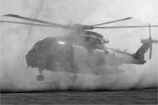
A Merlin Mk 3 in the desert creating its own
Degraded Visual Environment


Pilot’s Controllers

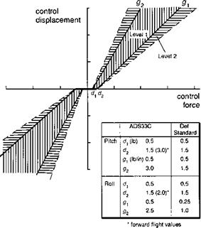
Evaluation of a helicopter’s flying qualities for a particular role will include an assess­ment of the mechanical characteristics of the pilot’s controls. No matter how good the response characteristics of the aircraft are, the overall flying qualities will be judged by the quality of the operation of the pilot’s controls reflected in a range of design features including cyclic self-centring, breakout forces and force gradients, deadbands and trimming actuators. Breakout forces that are too high, for example, can inhibit the pilot from making small, precise changes in flight path, and sluggish hydraulic systems can impede manoeuvrability. Slow trim motors can increase pilot workload and con­trol force gradients that are too light or too strong can spoil the use of smooth control action by the pilot. Nowadays there should be little controversy about what consti­tutes good controller characteristics when discussing central cyclic control sticks with large displacement; most medium to large helicopters have featured such devices with fixed-stiffness centring springs and operating through hydraulic actuation systems, for several decades. The range of acceptable characteristics needs to be fairly broad as the control forces generally have to be harmonized with the response characteristics. Figure 7.41 illustrates the general form of the control force/displacement relationship showing maximum and minimum values for the breakout force levels and gradients. The accompanying table gives values for Level 1 qualities as defined by ADS-33 (Ref. 7.1) and Def Stan 00970 (Ref. 7.37). Notable differences are in the roll force gradients and the maximum tolerable breakout forces, which appear to reflect traditional prefer­ences in the different countries’ armed services. Unlike fixed-wing aircraft, helicopters

Fig. 7.41 Control force versus control displacement for centre-sticks (Refs 7.1, 7.37)

do not usually include any artificial feel augmentation to cue the pilot in manoeuvres. However, a new requirement in ADS-33 for achieving Level 1 handling is for the stick force per g to lie between 3 lb (13 N) and 15 lb (67 N) per g (Ref. 7.1).

All current operational helicopters are fitted with a conventional cyclic centre – stick, collective lever and pedals, with a wide variety of different mechanical charac­teristics, reflecting the varying design preferences and, ultimately, pilot adaptability. Future helicopters with fly-by-wire control systems are likely to feature integrated side – stick controllers, and during the period between the late 1970s and late 1980s much of the basic research was undertaken to explore the potential of such devices (Refs 7.38­7.41). A key initial concern was whether equivalent handling qualities and performance could be achieved with sidesticks, considering the high levels of cross-coupling in heli­copters. Other issues related to the required level of stability and control augmentation to enable satisfactory performance with sidesticks, the trim mechanisms, grip designs and force-feel characteristics. The review paper of in-flight simulation activities at the Canadian Flight Research Laboratory (FRL), Ref. 7.41, offers the most comprehensive and coherent insight into what is currently known about passive sidesticks for heli­copters and forms the basic material for this short discussion. Sidestick control is now generally recognized as being a step in the right direction for helicopters and entirely commensurate with the development of fly-by-wire control. Significant improvements in cockpit ergonomics, including a dramatic influence on seating posture, relieving pilot fatigue and lower spinal damage, coupled with the potential for greater precision through integrated hand movements, are powerful reasons for their application.

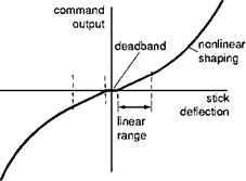
One of the first issues to be encountered with helicopter sidesticks was concerned with the need for command shaping to tailor the control sensitivity. Basically, to provide

Fig. 7.42 Typical nonlinear shaping function for sidestick controllers

the same levels of control power as with conventional controllers, the stick to response gearing would need to be nonlinear with a steepening gradient (Fig. 7.42). Linear gearing results in the control sensitivity being too high for small amplitude control inputs, giving rise to a strong tendency to overcontrol. A major question regarding the use of sidesticks has been how many control functions should be included in a single inceptor – 2, 3 or 4. Another question is related to whether there is a strong preference for displacement or force sensing. These two issues are not unrelated. Reference 7.41 reports pilot preference for a separate collective with a displacement sidestick, compared with no preference between 4 + 0 and 3 + 1 (collective) with a force sensing stick. The Canadian studies have demonstrated that four-axis control is entirely feasible for low-moderate gain tasks. For higher levels of aggression and higher bandwidth helicopters than the FRL Bell 205, little flight data have been published in the open literature, but it is suspected that 3 + 1 (collective) will be the extent of the integration. The Canadian research confidently proclaims that, to quote from Ref. 7.41:

The studies.. .consistently suggest that there is no evidence that the use of integrated side-mounted controllers in a helicopter.. .is detrimental to the overall handling qualities ofthe vehicle, nor that they demand ofthe pilot any unusual or exceptional skills in their use. Neither handling qualities nor pilot performance should control decisions as to the use of integrated sidesticks in helicopters.

For any specific application, however, there is an insufficient database to draw firm guidelines on the many design issues involved – the optimum force characteristics, grip shape and orientation, etc. ADS-33 reserves the section on sidesticks for future requirements. Two future projects are already committed to sidesticks. In Ref. 7.42, the design for the RAH-66 sidestick is referred to in passing as a three-axis (roll, pitch and yaw) sidestick with limited vertical axis capability, used in conjunction with the altitude hold function. In Ref. 7.43, the design of the NH-90 is shown to include a more conservative two-axis sidestick. Both will be passive, in the sense that the force characteristics will be fixed. New research into active sidesticks is underway at the time of writing. These should enable tactile cueing and more general, variable force – feel characteristics, tailored to the changing response types in an actively controlled helicopter.

Carefree flying qualities

A survey conducted with UK operational military pilots from all three services during the 1980s concluded that some 40% of the piloting workload derived from the need to monitor aircraft and flight envelope limits (Ref. 7.34). Some 70 pilots completed questionnaires in the survey and seven different aircraft types were addressed. One of the questions enquired as to which limits were the most demanding on pilot workload. From the response it was clear that the top two limits were engine/gearbox torque, selected by 75% of pilots, and rotorspeed, selected by about 60% of pilots. Some of the limits considered were actual limits, i. e., the pilot refers to an instrument showing the critical flight parameter with appropriate green and red zones, e. g., torque, engine temperature, rotorspeed. Others were derived limits, with parameters displayed on instruments giving essentially kinematic information about the aircraft state. Examples in this category are airspeed (reflecting rotor and fuselage loads), bank angle in steady turns and normal acceleration (reflecting rotor fatigue loads and static strength). Some limits are not normally presented to the pilot at all, e. g., sideslip and lateral velocity (reflecting rear fuselage strength) and yaw rate (reflecting tail rotor gearbox torque). The study reported in Ref. 7.34 also solicited pilot opinion of the potential value of different types of system that might assist in the monitoring and respecting of limits. The class of such systems was described as carefree handling systems and included head- up/down visual cues, audio cues, tactile cues and direct intervention control systems, with and without pilot override. The majority of pilots believed that the display of flight envelope limits on a helmet-mounted device would satisfy most of their concerns and would be effective in reducing the monitoring workload. Equally, the majority of pilots

considered that direct intervention control systems without pilot override would not be acceptable – about half of the pilots interviewed rated the potential effectiveness of such systems as zero. This last point should be placed in the context of fixed-wing aircraft experience, where most of the carefree handling features are in the direct intervention class; the only way the pilot has to override them is to turn them off. The results of this review of current perception and practice spawned a UK research activity into the functional attributes of helicopter carefree handling systems, which is ongoing at the time of writing. Selected results from the study are presented below.

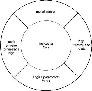
Carefree handling is a concept very familiar in the fixed-wing world, with Tornado, F-16, F-18 and Airbus A320 all featuring some form of system that protects the aircraft from exceeding limits; in general, as noted above, such systems cannot be overidden by the pilot unless he turns them off. The principal reason for this is that the protected limits are bounding regions where there is a high risk of loss of control, e. g., deep stall on the F-16, stall and spin departure on Tornado. In contrast, with helicopters, most of the lim­its are associated with structural considerations and, generally speaking, overstressing is preferable to hitting the ground. It is convenient to classify helicopter limits into four categories, as shown in Fig. 7.36, and related to structural/aerodynamic loads on the rotor or fuselage, engine speed and temperature, transmission loads and loss of control. For all but the last category (which has dominated the fixed-wing experience), the limits can be described as soft or with varying degrees of hardness. For example, a gearbox transient torque limit can be exceeded as the pilot pulls up to avoid an obstacle; perma­nent damage may have been done and the gearbox may need replacing, but the aircraft and crew have survived. It is for this reason that helicopter pilots, almost unanimously, are unwilling to accept carefree handling without an override capability. Before discussing the research efforts in this area it is important to give brief attention to

Table 7.5 Carefree handling features evaluated in Ref. 7.34

Configuration

Carefree handling features

1

none

2

visual warnings on HUD master warning light on coaming collective shaker for torque limits pedal shakers for lateral airspeed

3

monitoring of hub moment audible warnings for all limits

4

direct intervention protecting all limits manoeuvre limiting based on hub moment and g tactile cueing via hard-stops on sticks

5

torque demand protecting torque and rotorspeed direct intervention to protect limits manoeuvre limiting based on g tactile cueing via feel forces

potential loss of control regimes in helicopters. Vortex ring can be as severe for heli­copter pilots as stall is for fixed-wing pilots, and is a definite inhibition to manoeuvring vertically at low speed. Similarly, loss of tail rotor control can lead to a period of un­controlled yaw motion which can be disastrous in confined areas. Both these examples require good knowledge of the aircraft’s velocity relative to the air, which is notoriously inaccurate at low speed. A third example where the helicopter’s flight envelope is lim­ited by control problems is at low normal ‘g’, which is a particular concern for teetering rotors; control power can reduce to zero or even reverse at negative ‘g’. Helicopters have been lost because of excursions into unsafe control regions, and these corners of the flight envelope should not be neglected in the striving for safe and carefree handling.

In the study reported in Ref. 7.34, four combinations of different carefree handling features were trialled on the ground-based flight simulator at RAE Bedford. Table 7.5 lists the features evaluated. Configurations 4 and 5 featured direct intervention carefree handling. The error between the aircraft flight state and flight envelope limit was continuously estimated from measurements and triggered high-gain feedback control as the limit was approached. Warning systems included visual cues on a head-up display, audio tones and tactile cues fed through the variable force-feel control system. The vertical axis included a torque command system (TCS), as an alternative to the direct drive collective.

Six test pilots participated in the trial which included eight MTEs, designed to exercise the limits in both single and combined ways. The results of this study were quite illuminating. As predicted by the pilot opinion survey, protection of rotor torque and rotorspeed was valued the most. Contrary to the results of the pilot opinion reviews, the presentation of visual warning (flashing) cues on the head-up display (HUD) did not improve performance in the selected MTEs (configuration 2). Typically, pilots could be distracted by the visual warnings or even ignore them in high workload situations, hence limit transgressions were typically as numerous and high as without any carefree handling features (configuration 1). Of the warning systems, both audio and tactile were judged to be useful, because they reduced pilot workload although they still demanded pilot corrective action following the approach to, or exceedance of, the limit. The direct intervention systems scored the highest in terms of performance improvement and workload reduction, even when tactile cues, in the form of hard stops on the controls, inhibited the pilots from pulling through. On balance, the configuration with soft stops and stiffening control forces was preferred because pilots were more confident that the excess performance was available, if required.

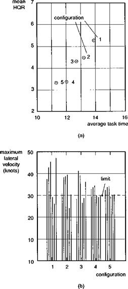
Figure 7.37 shows results for the 100-m sidestep manoeuvre. Mean HQRs are plotted against task time for the five configurations tested, showing the marked

Fig. 7.37 Comparison of simulation results with different carefree handling systems (Ref. 7.34): (a) mean HQRs; (b) peak lateral velocity excursions

improvement in task time and reduction in workload as the direct intervention systems are introduced (Fig. 7.37(a)). The principal flight limit of interest in this MTE was the lateral velocity, set at 30 knots, shown in Fig. 7.37(b). With only the warning sys­tems, 30% limit exceedances were typical, while the direct intervention system held the limits to within 10%. The achievement of marginal Level 1/2 HQRs for the MTEs flown with high levels of aggression on a ground-based simulator was a significant achievement when these trials were conducted and was attributed to the truly carefree manner in which the pilots were able to fly the tasks. The TCS was also well received by pilots and few cases of overtorquing occurred, even in multi-axis manoeuvres like the slalom and accel-decel. However, pilots did complain that the TCS appeared to reduce vertical axis performance, compared with the direct drive. The aircraft model used in the simulation was the RAE’s CSM, discussed earlier in this chapter, that possessed good Level 1 rate command flying qualities.

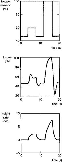
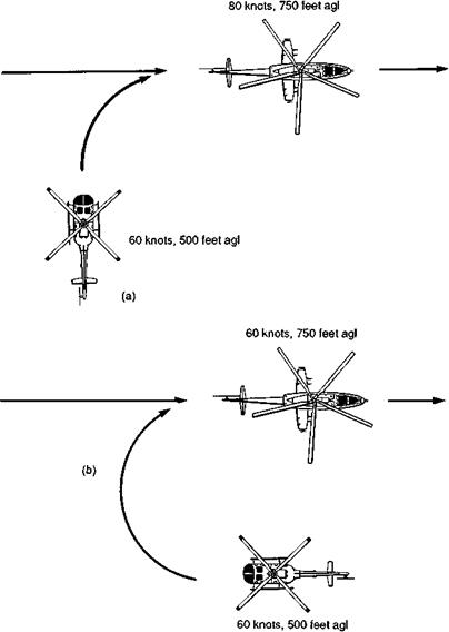
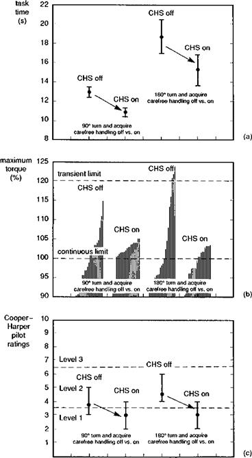
Since the completion of the UK conceptual studies into carefree handling, a num­ber of extensions and applications to different aircraft types have been accomplished. In Ref. 7.35, the problem of torque control received primary attention, applied to a simulation of the Bo105 helicopter. The sluggish vertical response characteristic of a TCS was demonstrated to be an inherent feature of the linear deadbeat torque response. The key to resolving the conflict, and thus conferring both crisp height rate response and torque command, lay in an innovative control law design technique that effectively varied the control law gains and structure as the limit was approached. Figure 7.38 il­lustrates the torque and height rate responses to small and large collective pulse inputs in the improved TCS design. For the small, 10% pulse, the crisp height response is accompanied by a 50% torque overshoot, which would, of course, be unacceptable if the test input had been applied closer to the maximum transient torque limit. For the larger input, demanding 50% torque, the height rate is constrained as the torque is held at the limit. For hands-off collective operation, a height hold, trim follow-up function automatically backdrove the collective to give the desired torque demand. This design was successfully trialled in a simulation on the DRA’s advanced flight simulator (AFS) with pilots flying air-to-air (ATA) target tracking and terrain following MTEs. The ATA MTEs are illustrated in Fig. 7.39, with the pilot’s task being to turn, climb and acceler­ate to acquire and track the moving target aircraft. Selected results from the simulation are illustrated in Fig. 7.40, showing a comparison of task time (a), transmission torque (b) and pilot HQRs (c) for the Bo105 with and without the torque carefree handling system. The carefree handling system enabled the target to be acquired 20% sooner, virtually eliminated unintentional limit transgressions and conferred Level 1 flying qualities on an otherwise Level 2 aircraft. The baseline aircraft simulated in this study was a Bo105 with full-authority active control system having solid Level 1 handling according to the ADS-33 criteria.

The results of the UK simulation programme appear quite convincing regarding the benefits of carefree handling qualities, at least for military operations, where the requirement to use the full performance potential of the helicopter on a regular basis is clear. In comparison, for civil operations there is no requirement for pilots to fly close to envelope limits, except in emergencies. It is therefore likely that the military application will continue to drive the enabling active control technologies; improved safety in civil operations will almost certainly be a fallout however. One of the findings of the results to date is that, given the safety of operations at the limits, pilots can be expected to fly there more often and, hence, aircraft incorporating carefree handling may well be

Fig. 7.38 Torque and height variations showing response shaping (Ref. 7.35)

exposed to more damaging fatigue usage. In this context, carefree handling will almost certainly need to be integrated with a fatigue usage monitoring system. The positive side to this additional complexity is that pilots, together with the carefree handling associate, can learn to fly with less damaging control strategies, if required. There will always be trade-offs involved, this time between performance and structural integrity, but the pilot should be able to make the decision which way to play the weightings, in any given situation.

One aircraft where a degree of carefree handling has been incorporated into the development programme is the Boeing-Bell V22 Osprey tiltrotor. Reference 7.36

Fig. 7.39 Air-to-air combat MTEs flown in carefree handling simulation (Ref. 7.35): (a) 90° turn, climb and accelerate to acquire target; (b) 180° turn and climb to acquire target

describes a number of innovative features aimed at protecting the aircraft from the effects of structural load exceedances, including

(1) limiting the rotor disc angle of attack during high load factor manoeuvres, using elevator to reduce the blade stall on the high disc loading rotor (helicopter mode);

(2) reduction of transient rotor flapping and yoke chord bending loads during aggressive pitch manoeuvres through limiting of high-frequency rotor commands (helicopter mode);

Fig. 7.40 Comparison of results with torque command carefree handling system on and off (Ref. 7.35): (a) task time; (b) maximum torque; (c) handling qualities ratings

(3) reduction of trim rotor flapping with elevator control (helicopter mode);

(4) reduction of transient mast and driveshaft torques in roll manoeuvres through roll rate feedback to differential rotor collective (airplane mode);

(5) prevention of nacelles from lifting off the downstop during aggressive roll manoeuvres through roll acceleration limiter (airplane mode);

(6) reduction of oscillatory yoke chord bending in pitch manoeuvres through tailoring pitch response characteristics.

The functionality of these design control law shaping features has been verified in simulation as reported in Ref. 7.36, highlighting that the loads in worst cases have been contained within the design limit loads, with an almost insignificant effect on handling qualities when flying the V-22 MTEs.

It could be argued that helicopters should be designed so that the flight limits are outside the capability of the aircraft, providing it remains within the OFE. Then the flying qualities engineer would not need to be concerned with artificial aids, and the aircraft would possess natural carefree handling. The pilot could never overtorque the gearbox, droop the rotor, pull too much g or exceed the sideslip or sideways ve­locity limits. The problem is that achieving this multi-objective design goal is actually very difficult, if not impossible, and with the classical helicopter design, the large control ranges to trim throughout the speed range provide sufficient control power at most flight conditions to inadvertently exceed one or other limit. With the tilt rotor, achieving a balanced design appears to be even more difficult and this aircraft has demonstrated that true carefree handling, where the full performance is not inhibited for safety reasons, will come only through the application of active flight control.
UCE augmentation with overlaid symbology

It should be obvious to the reader that NoE flight in the DVE makes considerable demands on the piloting task. The pilot needs support with both the stabilization and the guidance functions that he or she performs, and developments in display and control technologies have been so rapid during the late 1980s and early 1990s that flying qualities requirements for their effective use have been slow to catch up. Even as the chapters of this book are laid down the subject is expanding in several directions embracing and mixing the traditional flying qualities and human factors disciplines. It is therefore not appropriate to be definitive at this stage and as one of the contributors at a TTCP workshop on the subject (Ref. 7.33) remarked, ‘the more we know about the subject the less we seem to understand’. This old adage seems particularly germane to the present topic and is enhanced by the apparent notion that every pilot would prefer to design the display in his own image. Stepping back from the detail we can review the different kinds of information required by the crew during a DVE mission, and which are candidates for superposition on an outside world scene:

(1) primary flight path information for guidance and stabilization, including speed, height, attitude, heading, etc;

(2) guidance information related to special tasks, e. g., recovery to ship, pathway in the sky for flying NoE, target acquisition and weapon aiming;

(3) flight envelope and carefree handling cueing;

(4) aircraft system status, e. g., engine torque, AFCS modes;

(5) situational (tactical) awareness data, e. g., navigation – Where am I?, hazards – Where are the obstacles or the threats?

Any attempt to cram all the above information on to one display will quickly lead to crew overload. One of the basic messages in display design is to provide information only as and when it fulfils a useful function, hence increasing situational awareness or task performance. Unfortunately, the achievement of maximum situational awareness seems at times to be at odds with achieving a specific task performance. Put another way, well-designed displays can help to recover the full OFE, previously reduced for flight in the DVE, but only at the expense of high pilot workload caused by poor fields of view, poor resolution and the increased potential for spatial disorientation. There are times when the crew need to gaze down a narrow field-of-view ‘soda straw’ and see fine detail with precision symbology, and others when they need to scan continuously a 220° field-of-view scene overlaid with guidance symbology cues. Each makes different demands on the display technology but, ultimately, field of view and symbology content, like many display attributes, need provide only the functionality required for a given task.

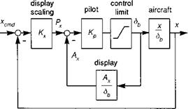
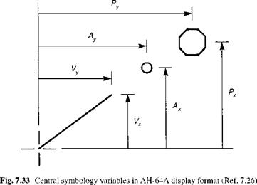
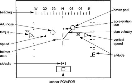
A good example of how symbology can be designed to aid specific tasks is provided by the AH-64A format shown previously in Fig. 7.31, in the so-called hover ‘pad capture’ or ‘bob-up’ mode. We supplement Fig. 7.31 with Figs 7.32 and 7.33, taken from Ref. 7.26, showing how the pilot uses this particular display to position the aircraft in the very-low-speed regime. The display is intended to aid the pilot maintain an accurate hover in a DVE. By ‘flying’ the acceleration cue into the hover pad and ‘flying’ both the cue and pad to the fixed aircraft reticle, the pilot is able to achieve a hover at a prescribed location, defined by the hover pad. Other flight data on the display include the heading, height and rate of climb and airspeed. The velocity vector indicates the aircraft’s horizontal inertial velocity. The box in the lower portion of the display shows the pilot where the FLIR image on the monocular display is positioned in the field of regard of the FLIR sensor. The three plan features that dominate the pilot’s attention during the pad capture MTE are shown in Fig. 7.33 and consist of the velocity vector, the acceleration cue and the hover pad. The 8-ft hover pad is driven on the display relative to the fixed reticle. The velocity vector has a full scale deflection of 12 ft/s, hence the display is intended to support very-low-speed manoeuvring to recover to the hover over a pilot-selected plan position. This display format provides

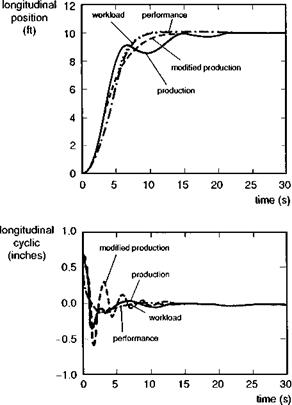
Fig. 7.34 Comparison of control inputs and aircraft responses for various display dynamics (Ref. 7.26)

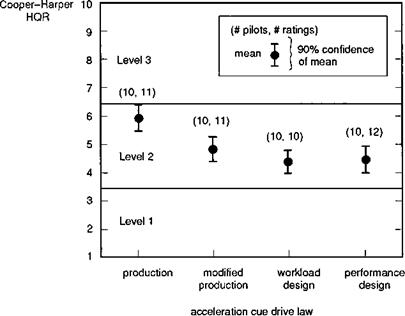
insight into how display dynamics can play a critical role in the overall achievement of task performance. Display dynamics are represented by the Ax /8b (translational acceleration to stick) transfer function in Fig. 7.32, defining the dynamic relationship between the acceleration cue (Ax) and the pilot cyclic stick (8b). As pointed out in Ref. 7.26, a pure gain display law would be the easiest to control but would be likely to lead to poor hover performance. At the other extreme, driving the acceleration cue with the trajectory demand would enable an improved task performance but would certainly require the pilot to work a lot harder. In the production version of the Apache display laws, a compromise is struck with a blend of the two. Reference 7.26 discusses three alternative drive law designs, designated the modified-production, performance and workload designs, that appear to offer significant improvements over the production version, principally by tailoring the response characteristics at frequencies above 2 rad/s, where the pilot will be working to make small and precise position corrections. Figure 7.34 shows the time responses of the aircraft horizontal position and longitudinal cyclic derived from an analytic simulation of Fig. 7.32. The theoretical predictions of improved performance and reduced workload are apparent. The results of an extensive piloted simulation exercise are also reported in Ref. 7.26, where ten pilots evaluated the different designs and concluded that the performance and workload designs were far superior. Figure 7.35 shows the HQRs for the different designs, indicating an improvement from poor to good Level 2 ratings for the pad capture task, with very high statistical significance.

The design of the display laws are clearly dependent on the response charac­teristics of the aircraft, as indicated conceptually in Fig. 7.32. For example, in the simulation trials conducted at DRA and reported in Ref. 7.32, the Ames display law

design methodology (Ref. 7.26), using the performance variant, was applied to derive laws that were compatible with the three response types evaluated, RC, ACAH and TRC. The general principle is to tailor the acceleration cue response to aircraft position x, attitude 9 and cyclic S, through transfer functions given by the general form

Ax x 9

-r(s) = fx(s)—(s) + f9 (s)-(s) + fSb (s) (7.8)

by matching to desired response and cancelling unwanted vehicle dynamics from the cue motion. The principles for achieving different design goals are described in Ref. 7.26. As with control law design for tailoring the aircraft response characteristics, display law design can be partially completed off-line using linear control techniques, but the final optimization still requires piloted evaluation. This example highlights some of the important integration aspects between displays that support pilotage and the response characteristics of the aircraft, hence any automatic guidance and control augmentation. Several other examples of emerging display formats for supplementing OVCs are discussed in Ref. 7.33 and indicate the potential of things to come, but are perhaps only stepping stones towards the tenuous aviation concepts of virtual reality and the computerized Pilot’s Associate that performs all the mechanical aviation functions, including pilotage, leaving the mission manager to direct the operation.

Flight in the DVE and agility represent the extremes of operation and obviously have a significant, although not exclusive, military relevance. Our third topic, carefree handling, is applicable to both civil and military operations, although once again the leading edge research has been forged by military requirements.

The usable cue environment

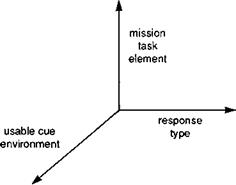
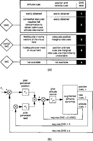
ADS-33 addresses these issues through the requirement for different response types (effectively the stabilization level) in different usable cue environments (UCE) to ensure Level 1 flying qualities. Of course, the quality levels still depend upon what the pilot is trying to achieve in terms of MTE, and Fig. 7.26 illustrates conceptually the three dimensions associated with this problem. We have briefly reviewed some of the issues involved previously in Chapters 2 and 6, but with this discussion of flying qualities in the DVE we are at the heart of the UCE concept and can give it more attention. One of the first discussions on the need for a more elaborate structure to define the quality of visual cues for rotorcraft operations appeared in Ref. 7.27. Hoh introduced the concept of the OVC scale in the form of Fig. 7.27, to establish the quality of task cues for the

Fig. 7.27 The outside visual cue scale (Ref. 7.27): (a) quantification of outside visual cues (OVC); (b) required outside visual cues for control

control of attitude and velocity or translational rate. In a flight test study to define the relative importance of such attributes as texture and field of view, Hoh developed the OVC concept and gathered pilot ratings for visual cues – the so-called VCRs (Ref.

7.28) . A conclusion of this study was that the stabilization function can be performed well with only a narrow field of view but fine-grain texture is vital, and also that the guidance function, and more general situation awareness, requires a wide field of view with macro texture. The OVC scale was further developed into the UCE (Refs 7.28,

7.29) to measure the usefulness and quality of artificial vision aids. The UCE scale along with the adjectival meanings of the different subjective VCRs are shown in Fig. 7.28. Pilots must rate the visual cues based on their ability to perform various low – speed/hover MTEs (with the DVE, rather than day, task performance requirements). The method for deriving the UCE is described in Refs 7.29 and 7.30. VCRs from at least three test pilots must be used to derive the UCE. Once derived for a given task,

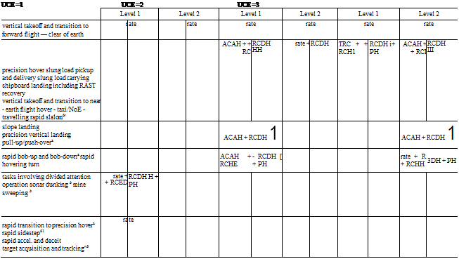
significant stability or guidance augmentation functions are added. This is to ensure that the VCRs are not corrupted by an aircraft’s poor handling qualities. The UCE innovation is used in ADS-33 to identify the requirement for enhanced stability augmentation and/or display augmentation. The requirement is summarized in Table 7.4, illustrating the response types needed to confer Level 1 flying qualities in different UCEs. Thus, if an aircraft with its vision aids is required to operate in a UCE 3 then only the full augmentation provided by translational rate command/position hold (TRCPH) will confer Level 1. Alternatively, if the vision aids could be enhanced to improve the UCE from 3 to 2, then attitude command/attitude hold (ACAH) will be sufficient. If a UCE 3 could be upgraded to 1, through the provision of high-quality world scene cues inside the cockpit, then the lowest level of augmentation provided by rate command (RC) will be sufficient. We can now see the trade-off between vision, or guidance, aids and control, or stability, augmentation, and with both technologies advancing rapidly in the 1990s it is likely that a wide variety of options will be available on future types depending on the character of the tasks. For example, recovering civil or military helicopters to small ships in poor visibility will certainly require both improved guidance and stabilization aids if the operational risks are to be significantly reduced.

The basic substantiating data for the requirements of Table 7.4 came originally from flight test data on the Canadian Bell 205 in-flight simulator (Ref. 7.31). Tests were conducted with varying levels of stability augmentation while the pilot flew with night vision goggles, fogged to vary the UCE. Later, a more systematic piloted simulation investigation was performed on the NASA vertical motion simulator (VMS), designed specifically to explore the need for enhanced stability augmentation in DVE (Ref.

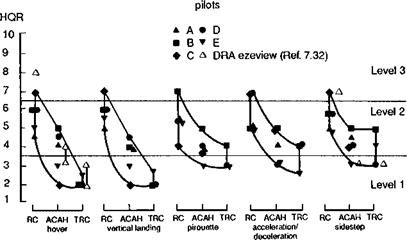
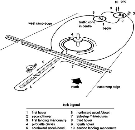
7.30) . In Fig. 7.29, taken from Ref. 7.30, HQRs are shown plotted against response type for five low-speed MTEs flown in the sequence – hover, hover, vertical landing, pirouette, 2 accel/decels, sidesteps, hover, hover and landing – as shown in Fig. 7.30. The CGI visual scene was degraded to UCE 3 by fogging the far field and reducing the micro- and macrotexture in the near – to mid-field. The HQRs illustrate clearly how the workload reduces as the augmentation is increased, poor Level 2 ratings characterizing the RC response type in all MTEs. Level 1 ratings were given for the TRC in most of the MTEs, with the ACAH system generally lying in the good Level 2 region. The results were obtained without any visual display augmentation. In a series of similar, more recent, trials using the advanced flight simulator at the DRA, pilots viewed the UCE 3 world scene through a monochrome, bi-ocular HMD (Ref. 7.32) shown previously in Fig. 2.49. The outside world scene, with an allround field of regard, but only a 48 x 36° field of view, was overlaid with different symbology sets to aid the pilots’ stabilization and guidance tasks. HQR data for two DVE tasks from ADS-33, the recovery to hover and sidestep, are superimposed on the results in Fig. 7.29 for comparison. In the AFS trials, the UCE 3 was obtained with a combination of a sparse outside world scene and superimposed symbology; strictly speaking, the data cannot be directly compared with the VMS data, where the pilots flew with the outside world scene alone. Nevertheless, the data correlate very well and confirm the marked change in performance and workload with level of stability augmentation. One of the symbology sets evaluated in Ref. 7.32 is illustrated in Fig. 7.31 and is based on the horizontal situation display featured in the current generation AH-64A helicopter. We shall discuss this type of format in more detail later in this section. Results from the AFS trial have highlighted the importance of the height hold facility to ensure Level 1 ratings with the ACAH and TRC response types. Another result of the AFS trial questioned

Подпись: UCE =1 UCE =2 UCE =3 Level 1 Level 2 Level 1 Level 2 Level 1 Level 2 vertical takeoff and transition to forward flight — clear of earth r ate rate rate rate rate rate precision hover slung load pickup and delivery slung load carrying shipboard landing including RAST recovery vertical takeoff and transition to near - earth flight hover - taxi/NoE - travelling rapid slalom6' ACAH + + RC RCDH HH rate + RCDH TRC + + RCH1 RCDH i+ PH ACAH + + RCI RCDH Ш slope landing precision vertical landing pull-up/push-overa ACAH + RCDH 1 ACAH + RCDH 1 rapid bob-up and bob-downa rapid hovering turn ACAH + RCHE - RCDH [ + PH rate + R + RCHH 3DH + PH tasks involving divided attention operation sonar dunking b mine sweeping b rate + + RCED RCDH H + PH rapid transition to precision hovera rapid sidestep61 rapid accel. and deceit target acquisition and tracking^6 ra te
ahigh levels of aggressiveness may not be achieveable for

Подпись:UCE = 2 and 3.

^these tasks are normally accomplished in an environment where visual cueing may be consistent with UCE = 2 or 3 even in ‘day VFR conditions’.

^increase in rank toTRC not recommended for pitch pointing tasks.

Fig. 7.29 HQRs for different response types flying various MTEs (Ref. 7.30)

Fig. 7.31 Low-speed display symbology format used in the AH-64A Apache (Ref. 7.26)

the value of attitude bars on displays during very-low-speed MTEs, particularly when attitude stabilization is provided artificially, as in the ACAH and TRC response types. The bars did not provide significant improvements with the RC response type. Also, the dynamic cues provided by the moving bars could be distracting while not fulfilling a useful function. This introduction to the use of symbology to supplement the OVC brings us to the final topic of this section.

Flying in DVE

Military helicopter operations require pilots to fly at low level in the NoE at night and in bad weather, and clearly the DVE has a major impact on all three pilotage functions – navigation, guidance and stabilization. To a lesser extent, recovery of civil transport helicopters in poor weather to confined landing sites, such as ships and building tops, also makes additional demands on flying qualities. Pilots need support for all three functions described above. Fear of getting lost may well be a primary concern but navigation is not directly a flying qualities issue. We are more concerned with guidance and stabilization. As the OVCs degrade, pilots will have two related concerns. First, they will need to supplement the disappearing outside world position and velocity cues to enable them to continue low-level flight without risk of bumping into things, with potentially catastrophic consequences. Second, they will need to fixate

on their attitude instruments, particularly in gusty conditions, to prevent the aircraft departing from trim or level flight. Without any artificial guidance and stabilization aids, these requirements are clearly incompatible (the one requiring the pilot to keep eyes out, the other to fix gaze on displays) and a pilot will sensibly climb out of the unsafe flight condition. To enable helicopters to continue operations in low-level DVE, special guidance and control technologies are being developed, and requirements on these have been clarified in the new parlance of ADS-33.

It is recognized that the guidance function can really be augmented only through the provision to the pilot of augmented visual cues projected either onto the visor of his helmet or onto cockpit panels, either head-up or – down. The first generation of such displays can be found in systems like the AH-64A Apache helicopter with the integrated helmet and display system (IHADS), which provides a thermal image from a forward-looking infra-red sensor (FLIR) onto a monocular display, overlaid with flight path symbology and integrated and slaved with the pilot’s helmet (Ref. 7.26). We will discuss this as representative of current operational technology later in this section. It is also recognized that the stabilization task can be augmented properly only through feedback control functions, augmenting the poor natural damping and aerodynamic stiffness of the helicopter (which is practically absent at low speed). Two outstanding questions arise from this simple analysis – how best to ensure a harmonious integration of the guidance and stabilization augmentations for flight in DVE and what trade-offs exist in the design of the related display and SCAS technologies.

Pilotage functions

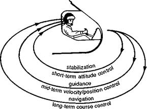
To initiate the discussion it is useful to reflect on the piloting task and to review our pre­vious classification into three subtasks – navigation (and general situation awareness), guidance and stabilization. The discussion will be aided by Fig. 7.25 showing the pilot performing as the feedback element in the closed-loop task. Navigation is concerned with knowing where you are and where you are going – the very outer loop in Fig. 7.25, with typical time/space scales measured in min/km. Most of the time, the pilot will not

be concerned with applying control actions to support the navigation function. Typi­cally, he will be following maps that lead him from one ‘way-point’ to the next, when he applies control to direct the aircraft on to the next heading and perhaps speed and height. Flying at low level and in the nap of the earth (NoE) makes considerably more demands on piloting, particularly on the inner-loop functions. The guidance function works within time/space scales of a few seconds and tens of metres and is concerned with avoiding obstacles and the ground. The closer the pilot has to fly to obstacles, the more arduous the guidance task becomes and, typically, the slower the groundspeed selected. A general rule of thumb is that pilots will select a speed that gives them a perception – action timeframe of between 3 and 5 s. Hence, a 3-s pilot may elect to fly at 40 knots to give a 60-m straight line see-ahead distance for avoiding obstacles. At 80 knots the same pilot would need to be able to see 120 m ahead. These are minimum distances and pilots normally fly with much greater safety margins. In the same terrain, for example, a different pilot may prefer to fly with less urgency, making more spare capacity available for observation, and chose to fly at 20 knots, giving a 3-s to fly 30 m, or 6-s see-ahead time in a DVE with a 60-m visibility. Similarly, the vertical flight path excursions caused by disturbances will increase with increasing forward speed, forcing the pilot to fly higher to maintain the same level of safety. In the NoE, a general rule is to trade feet for knots – 10 knots at a height of 10 ft, 60 knots at a height of 60 ft. The selected overall piloting strategy for guidance will depend on a number of factors – pilot familiarity with the terrain and experience of NoE flying, the aircraft response characteristics, the level of task urgency and last, but perhaps most important of all, the quality of the OVCs. This is the cue to the main subject of this section but before discussing flying qualities in the DVE in more detail, we need to examine the third, and perhaps most, distinguishing feature of helicopter pilotage – stabilization.

Automobile drivers are generally unconcerned with stability, except in tight curves or on slippery surfaces, or perhaps with faulty steering/uneven tyre wear or balance. However, without some form of artificial stability augmentation, helicopter pilots need to make continual corrections with their controls to ensure that the aircraft does not depart from a prescribed flight path. Different helicopters have their own particular stability characteristics and problems, but most suffer from natural instabilities in both longitudinal and lateral motions that are difficult to cure completely with limited authority artificial stability augmentation. Control of instabilities is primarily achieved through attitude as illustrated in Fig. 7.25 and often requires the pilot to be continuously attentive to flight path control, hence contributing significantly to pilot workload.